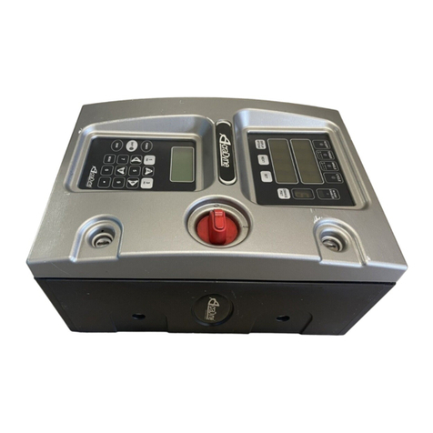
Aimco ArcaDyne IEC4W User manual

LIT-MAN942 rev_11-01-19
Gen IV Controller Operator Manual
IEC4W, IEC4W1, and IEC4W2

Page 2of 84
AcraDyne GEN IV iEC
CONTROLLER MANUAL
Important Safeguards: For your protection, please read these instructions completely. Keep this
manual for future reference. Carefully observe and comply with all warnings, cautions and
instructions placed on the equipment or described in this manual.
Contents
1 Safety Information....................................................................................................................................................................4
2 Controller Diagrams.................................................................................................................................................................5
2.1 Front Panel .........................................................................................................................................................................5
2.2 Side View............................................................................................................................................................................6
3 Initial Set Up ..............................................................................................................................................................................7
3.1 Connecting to the Controller ...........................................................................................................................................8
3.2 Quick Set Up (Default PSets from Tool) ......................................................................................................................... 13
4 Home Page (Main Menu) ......................................................................................................................................................13
4.1 Run.................................................................................................................................................................................... 14
4.2 PSet...................................................................................................................................................................................17
4.2.1 Add New PSet....................................................................................................................................................................17
4.2.2 Edit PSet ..............................................................................................................................................................................19
4.2.3 Advanced Options ...........................................................................................................................................................20
4.2.4 Manage PSets....................................................................................................................................................................20
4.2.5 PSet Stages .........................................................................................................................................................................21
4.2.5.1 TC-Torque Control Stage ........................................21
4.2.5.2 TC_AM Torque Control Angle Monitor Stage ......22
4.2.5.3 AC-TM Angle Control Torque Monitor Stage.......23
4.2.5.4 TC_AC Torque Control Angle Control Stage.......24
4.2.5.6 Delay Stage..............................................................25
4.2.5.7 Ergo Stop Stage .......................................................25
4.2.5.8 Brake Stop Stage .....................................................25
4.2.5.9 Unfasten Stage.........................................................26
4.2.5.10 AC_TA Angle Control Torque Averaging Stage27
4.2.5.11 Sync Stage..............................................................28
4.2.5.12 Thread Forming Stage...........................................28
4.2.5.13 AC_TCOMP Angle Control Torque Compensation Stage 29
4.2.5.14 AC_TCOMP Display of Torque Compensation Value 30
4.2.5.15 Yield Control...........................................................30
4.2.6 Multistage Rundown Evaluation and Reporting ..........................................................................................................31
4.2.7 Multiple Stage Rundown Examples................................................................................................................................32
4.3 Job.................................................................................................................................................................................... 34
4.3.1 Add New Job.....................................................................................................................................................................34
4.3.2 Advanced Options ...........................................................................................................................................................35
4.4 Results............................................................................................................................................................................... 37
4.4.1 Saving Rundown(s)............................................................................................................................................................38
4.5 Controller .........................................................................................................................................................................39
4.5.1 Tool Setup ...........................................................................................................................................................................39
4.5.1.1 Lock Tool on Reject .................................................40
4.5.1.2 Buzzer.........................................................................40
4.5.1.3 Headlight ..................................................................40
4.5.1.4 Start Input Configuration ........................................41
4.5.1.5 MFB (Multi-Function Button) ...................................42
4.5.1.6 Disassembly ..............................................................43
4.5.1.7 TubeNut.....................................................................44
4.5.1.8 Past Service and Calibration .................................44
4.5.2 I/O ........................................................................................................................................................................................45
4.5.2.1 Anybus/ Modbus TCP/Ethernet IP Inputs..............45
4.5.2.2 Anybus/Modbus TCP/Ethernet IP Outputs ...........46
4.5.3 Communication Interfaces..............................................................................................................................................47
4.5.3.1 Ethernet.....................................................................47
4.5.3.2 System Port ...............................................................47
4.5.3.3 Spindle USB Port .......................................................48
4.5.4 Protocols .............................................................................................................................................................................48
4.5.5 Front Panel Buttons............................................................................................................................................................48

Page 3of 84
4.5.6 Set Time ...............................................................................................................................................................................49
4.5.7 Remote Connections........................................................................................................................................................49
4.5.8 Master Spindle Setup ........................................................................................................................................................50
4.5.9 Setting up Multi-Spindle Network ....................................................................................................................................50
4.5.10 Languages........................................................................................................................................................................53
4.6 Tool ...................................................................................................................................................................................53
4.6.1 Tool Setup ...........................................................................................................................................................................54
4.6.2 Service Log .........................................................................................................................................................................54
4.6.3 Button Calibration .............................................................................................................................................................55
4.6.4 Torque Calibration.............................................................................................................................................................55
4.6.5 Torque Calibration Routine..............................................................................................................................................56
4.6.6 TID Parameters ...................................................................................................................................................................56
4.6.7 TID Memory.........................................................................................................................................................................57
4.7 Accessories ......................................................................................................................................................................57
4.8 Diagnostics.......................................................................................................................................................................58
4.8.1 Controller Overview ..........................................................................................................................................................58
4.8.2 Controller Status.................................................................................................................................................................59
4.8.3 Tool Overview ....................................................................................................................................................................59
4.8.4 Live Tool...............................................................................................................................................................................60
4.8.5 Record Logs .......................................................................................................................................................................60
4.8.5.1 Change Log .............................................................60
4.8.5.2 Information Log........................................................60
4.8.5.3 Error Log ....................................................................60
4.8.5.4 All................................................................................60
4.8.6 System Status......................................................................................................................................................................61
4.8.7 I/O Diagnostics...................................................................................................................................................................61
4.8.8 Network Diagnostics .........................................................................................................................................................62
4.8.9 Extended Logging.............................................................................................................................................................62
4.9 Login.................................................................................................................................................................................62
4.10 Advanced......................................................................................................................................................................63
4.10.1 Default Login Setup.........................................................................................................................................................63
4.10.2 Results Archive .................................................................................................................................................................64
4.10.3 Import Settings .................................................................................................................................................................65
4.10.4 Export Controller ..............................................................................................................................................................66
4.10.5 Update Controller ...........................................................................................................................................................66
4.10.6 Backup Restore................................................................................................................................................................67
4.10.7 Restore Factory Defaults ................................................................................................................................................68
4.10.8 Previous Software .............................................................................................................................................................69
4.10.9 Calibrate Touch Screen .................................................................................................................................................69
4.10.10 Soft Reboot.....................................................................................................................................................................70
5 Glossary of Terms ...................................................................................................................................................................71
6 Icons Defined .........................................................................................................................................................................73
7 Stop Codes .............................................................................................................................................................................74
8 Error Codes .............................................................................................................................................................................75
9 Dual-Lever Tools Requiring Two-Handed Operation ...........................................................................................................78
10 Dimensions ...........................................................................................................................................................................79
11 Specifications .......................................................................................................................................................................80
12 Troubleshooting....................................................................................................................................................................81
13 AIMCO Warranty ..................................................................................................................................................................83

Page 4of 84
1 Safety Information
General Power Tool Safety Warnings
WARNING
Read all safety warnings and instructions.
Save all warnings and instructions for future
reference.
1. Work area safety
a. Keep work area clean and well lit.
b. Do not operate power tools in
explosive atmospheres, such as in the
presence of flammable liquids, gases
or dust.
c. Keep children and bystanders away
while operating a power tool.
2. Electrical safety
a. Power tool plugs must match the
outlet. Never modify the plug in any
way. Do not use any adapter plugs
with earthed (grounded) power tools.
b. Avoid body contact with earthed or
grounded surfaces, such as pipes,
radiators, ranges and refrigerators.
c. Do not expose power tools to rain or
wet conditions.
d. Do not abuse the cord. Never use the
cord for carrying, pulling or
unplugging the power tool. Keep
cord away from heat, oil, sharp
edges or moving parts.
e. When operating a power tool
outdoors, use an extension cord
suitable for outdoor use.
f. If operating a power tool in a damp
location is unavoidable, use a
residual current device (RCD)
protected supply.
3. Personal safety
a. Stay alert, watch what you are doing
and use common sense when
operating a power tool. Do not use a
power tool while you are tired or
under the influence of drugs, alcohol
or medication.
b. Use personal protective equipment.
Always wear eye protection.
c. Prevent unintentional starting. Ensure
the switch is in the off-position before
connecting to power source and/or
battery pack, picking up or carrying
the tool.
d. Remove any adjusting key or wrench
before turning the power tool on.
e. Do not overreach. Keep proper
footing and balance at all times.
f. Dress properly. Do not wear loose
clothing or jewelry. Keep your hair,
clothing and gloves away from
moving parts.
4. Power tool use and care
a. Do not force the power tool. Use the
correct power tool for your
application.
b. Do not use the power tool if the
switch does not turn it on and off.
c. Disconnect the plug from the power
source and/or the battery pack from
the power tool before making any
adjustments, changing accessories,
or storing power tools.
d. Store idle power tools out of the
reach of children and do not allow
persons unfamiliar with the power
tool or these instructions to operate
the power tool.
e. Maintain power tools. Check for
misalignment or binding of moving
parts, breakage of parts and any
other condition that may affect the
power tools operation. If damaged,
have the power tool repaired before
use.
f. Use the power tool, accessories and
tool bits etc., in accordance with
these instructions, taking into
account the working conditions and
the work to be performed.
5. Service
a. Have your power tool serviced by a
qualified repair person using only
identical replacement parts.

Page 5of 84
2 Controller Diagrams
2.1 Front Panel
LED Indicator Lights
Green LED: Indicates tightening cycle meets specified parameters.
Red LED: Indicates tightening cycle rejected for exceeding high torque.
Red Flashing LED: Indicates low torque. Tightening cycle was rejected for not achieving low torque.
Yellow LED: Indicates High Angle. Tightening cycle was rejected for exceeding high angle.
Yellow Flashing LED: Indicates Low Angle. Tightening cycle was rejected for not achieving low angle.
Blue LED: Tool is In-cycle above threshold.
Torque/Angle Display
Ethernet Port RJ45 -Connection used to connect external computer to configure/monitor controller
PSeT Switch - Changes PSet/Job display
Power Switch - Turn Controller On and Off
USB Port - Import and Export of Data
System Port - USB Connection used to connect external computer to configure/monitor the controller

Page 6of 84
2.2 Side View
1. Power Cord Connection
2. Tool Connector: 19 Pin Standard connection point for tool cable
3. Fan Connector: For tools equipped with an on-board cooling fan.
1
2
3

Page 7of 84
3 Initial Set Up
Step 1
Connect tool cable to Tool Connector. Cable consists of a male pin set housed in a molded 19
pin connector with a polarizing notch. Align tool cable notch with tool connector notch on
the controller and insert cable. Securely thread connector coupler to controller body.
Step 2
Repeat above process to connect tool cable to AcraDyne tool being used with the controller.
Step 3
Plug female end of power cable into Power Cable Connector.
Step 4
Plug male end of power cable into appropriate power source.
Due to a variety of 230VAC power outlets, the standard power cable plug-end provided with the
controller may need to be modified in order to connect to local 230Vac power outlets. AcraDyne has a
wide variety of country-specific power cord options available. Check with your authorized AcraDyne
representatives to see if your specific configuration is available. In any case, connection to local power
should be made in consultation with a qualified electrician.
Step 5
The Secondary Protective Earth Attachment needs to be clamped properly to ground.
1
Step 6
Turn controller on by pushing the Power Disconnect Switch to the POWER ON position, a light
indicates power on.
NOTE: Warning will appear if the controller is power cycled too quickly.
If a fault appears, Power Down controller, wait a mimimum of 10
seconds between controller Power Down, and Power Up to clear error
and restart controller.

Page 8of 84
3.1 Connecting to the Controller
There are three ways to program/communicate with the controller:
•Controller touch-screen console
•System Port: (USB connection) Direct connection to controller.
•Ethernet Port: Via direct connection or LAN.
Touchscreen Console
Controller functions and programming can be accessed directly through the touch-screen.
1. Power on controller.
2. Run screen will appear.
3. Controller is ready for use.

Page 9of 84
Connecting via the System Port directly to PC
The following is an example using Window 7. Your screen may look different depending on the
operating system.
Windows USB Setup:
Step 1 Power on PC and controller, allow enough time for them to become fully operational.
Step 2 Attach controller to PC using a USB 2.0 A-B cable. If this is the first time connecting the devices,
wait for Windows to install the RNDIS driver. This should happen automatically.
Step 3 After the driver is installed, go to ‘Control
Panel’.
Step 4 Go to ‘Network and Internet’.

Page 10 of 84
Step 5 Go to ‘Network and Sharing Center’.
Step 6 Go to ‘Change adapter settings’.
Step 7 Find the Local Area Connection that is using the
‘USB Ethernet/RNDIS Gadget’ network. Right click this
network and go to ‘Properties’.
Step 8 In Properties window select ‘Internet Protocol
Version 4’ and click ‘Properties’.

Page 11 of 84
Step 9 In ‘Properties’, set the IP address to a static
address.
Type an IP address of 192.168.1.5 (Any address on the same
subnet as the controller will work).
Set subnet mask to 255.255.255.0
Step 10 To connect to the controller. Open a browser such as Chrome or Firefox. Enter 192.168.1.4, the
default system port IP address.
You will see the controller software on your computer sceen.

Page 12 of 84
Connecting using the Ethernet Port Directly to PC
•Make a physical connection from the PC to the controller’s Ethernet (1) port using an ethernet
cable.
•Verify the controller’s Ethernet (1) IP address by using the touchscreen or a system port browser
session and going to Controller -> Communication Interfaces -> Ethernet. For controllers that
have an LED display, the IP address can also be found by using the toggle button to show it on
the secondary LED display.
•If the controller’s IP address has not been configured, set the IP address to 10.10.30.99, the
Subnet Mask to 255.255.255.0, and the Gateway to 0.0.0.0.
•Set the static IP address of the PC to 10.10.30.98 and subnet mask to 255.255.255.0. (For
instructions, see the example earlier in this section.)
•To connect to the controller, open a browser such as Chrome or Firefox and navigate to the
controller’s Ethernet address.
•If the connection is successful the controller’s run screen will be displayed in the browser.
Connecting using the Ethernet Port Directly or via LAN to PC
•Make a physical connection from controller’s Ethernet (1) port to a network router connected to
the LAN using an ethernet cable.
•Verify the controller’s Ethernet (1) IP address by using the touchscreen or a system port browser
session and going to Controller Communication Interfaces Ethernet. For controllers that
have an LED display, the IP address can also be found by using the toggle button to show it on
the secondary LED display.
•If the controller’s IP address has not been configured, consult your Network Administrator for
selecting a correct IP address, Subnet Mask, and Gateway for your network.
oNOTE: Controller does not have a DHCP client, it will not automatically configure itself
with a useable IP address.
•To connect to the controller, open a browser such as Chrome or Firefox and navigate to the
controller’s Ethernet address.
•If the connection is successful the controller’s run screen will be displayed in the browser

Page 13 of 84
3.2 Quick Set Up (Default PSets from Tool)
On the Home Page press:
to accept default PSet Parameters.
This will generate three generic PSets for the tool connected to the controller. It will automatically use
the 40%, 60%, and 80% of the rated maximum torque of the tool in a two-stage Torque Control Strategy
(TC). A prompt will display rated Max Torque and Max RPM of the connected tool for reference. These
Psets can be modified to meet application requirements.
4 Home Page (Main Menu)

Page 14 of 84
4.1 Run
The Run Screen is essentially the dashboard of the Gen IV controller
and provides a look at real-time information regarding rundowns.
Indicates the current JOB.
Indicates the current PSet in which you are operating.
Indicates accepted rundown.
Indicates failed rundown.
Displays Torque and Angle for current rundown.
Time (in-cycle) screen
Graph displays curves representing Torque (black trace) and Angle (blue trace). The blue left arrow at
the origin of the graph will change the X-axis of the rundown curve from Time (In–Cycle) to Time
(Overall) and Angle.
Below the graph is a historical table that will give information and status of the most recent rundowns,
including current PSet, accepted/failed rundown status, torque, and angle.
Arrows allow user to scroll left or right for viewing real time Job
information such as Run Screen or rundown indicators.
Home tab will return user to the Home Page

Page 15 of 84
Click for curve detail.
Click on arrow to change curve X axis.
Choose Time in-cycle,Time
Overall, or Angle screen
Angle Screen
Time Overall Screen

Page 16 of 84
Run Screen (Job display information)
Run Screen displays real-time Job information.
PSet View Screen Large Screen Indicators and Audit information (Easy Mode)
The large screen indicators are helpful in viewing real-time results of the rundown from a distance.
Curve View
Simple View
Parameter Set View

Page 17 of 84
4.2 PSet
Parameter Settings (PSets) control the fastening process. The following describes the different fastening
stratagies and how to setup the basic PSet parameters necessary to perform a fastening. Up to 256 PSets
are available.
4.2.1 Add New PSet
On Home Page press the tab.
On PSets screen (right) press to add a new Pset.
Stage Torque and RPM at a glance.

Page 18 of 84
On Add New PSet screen(below)enter appropriate values.
PSet Number: Current PSet to be added.
Torque Units: Unit of measure.
In Cycle Torque: Threshold value at which tool is “In Cycle” and results
from the Rundown will be reported.
Cycle Complete Torque:Torque level that determines completion of a
fastening cycle.
Time Limit(s) (sec): Maximum allowable time tool is allowed to run.
Advanced Options: (see 4.2.3)(
PSets (See 3.2 Quick Setup)
Manage (see 4.2.4 Manage PSets)
Once PSet values are entered press to enter Add New Stage screen.
Add New Stage
A single stage or multiple stages build a PSet. Up to 20 stages can be
assigned per PSet.
The following stage options are available:
Once the desired stage(s) are selected and configured, press to save stage and again to save the
PSet and return to initial PSet menu.
Next Press to go to the RUN screen or to return to the Home page. The tool should now be
operational and you are ready to run a configured PSet.

Page 19 of 84
4.2.2 Edit PSet
On Home page press:
On the PSet screen (left) click on the
desired PSet you would like to edit.
Click on the Edit button to make
changes in the Edit screen (right).
If further Stage changes are needed click the Edit button again to enter Edit Stage screen (below).
Once desired changes are made click twice to save changes.

Page 20 of 84
4.2.3 Advanced Options
PSet Name: Add PSet name if desired (up to 10 characters).
Thread Direction: Defines fastening direction (default is right hand).
Re-hit/Reject Parameters: Prevents the fastening of an already
tightened fastener. If enabled, tool will stop and the rundown will be
aborted, if the angle of rotation between the Re-hit Reference
Torque and the In-Cycle Torque is less than the Re-hit Angle Count.
NOTE: If the attempted rundown is a Re-hit, it will not be reported or
recorded.
Re-hit Reject Enable: Enables the feature.
Re-hit Reference Torque: This torque value is the start of the angle
count that determines a Re-hit. (This value should be lower than the
In Cycle Torque specified in the PSet.)
Re-hit Angle Count: If the angle count between the Re-hit Reference
Torque and the In Cycle Torque is less than this value, the rundown is
determined to be a Re-hit.
4.2.4 Manage PSets
Save PSets to Browser
Allows the PSet information to be saved to the local PC
connected to controller. PSet information is saved as a .txt file and
can be opened using any text editor such as WordPad. It can also
be opened with Excel. The format of the .txt file is tab separated
values.
Export PSets to Browser
Save the PSets as a database file to the PC connected to
controller. These PSets can later be imported to another controller.
Import PSets from Browser
Import previously exported PSets to controller.
Delete PSets
Enables deletion of selected PSets.
Save/Export/Import USB
Same as above using a USB Memory Stick
This manual suits for next models
2
Table of contents
Other Aimco Controllers manuals

Aimco
Aimco AcraDyne Gen IV User manual

Aimco
Aimco AcraDyne Gen IV User manual

Aimco
Aimco UEC-4800EX User manual

Aimco
Aimco AcraDyne Gen IV iAC User manual

Aimco
Aimco AcraDyne Gen IV Manual

Aimco
Aimco AcraDyne iBC-Z User manual

Aimco
Aimco UEC-4800EPL User manual

Aimco
Aimco AcraDyne Parts list manual

Aimco
Aimco AcraDyne iPC User manual

Aimco
Aimco iEC User manual