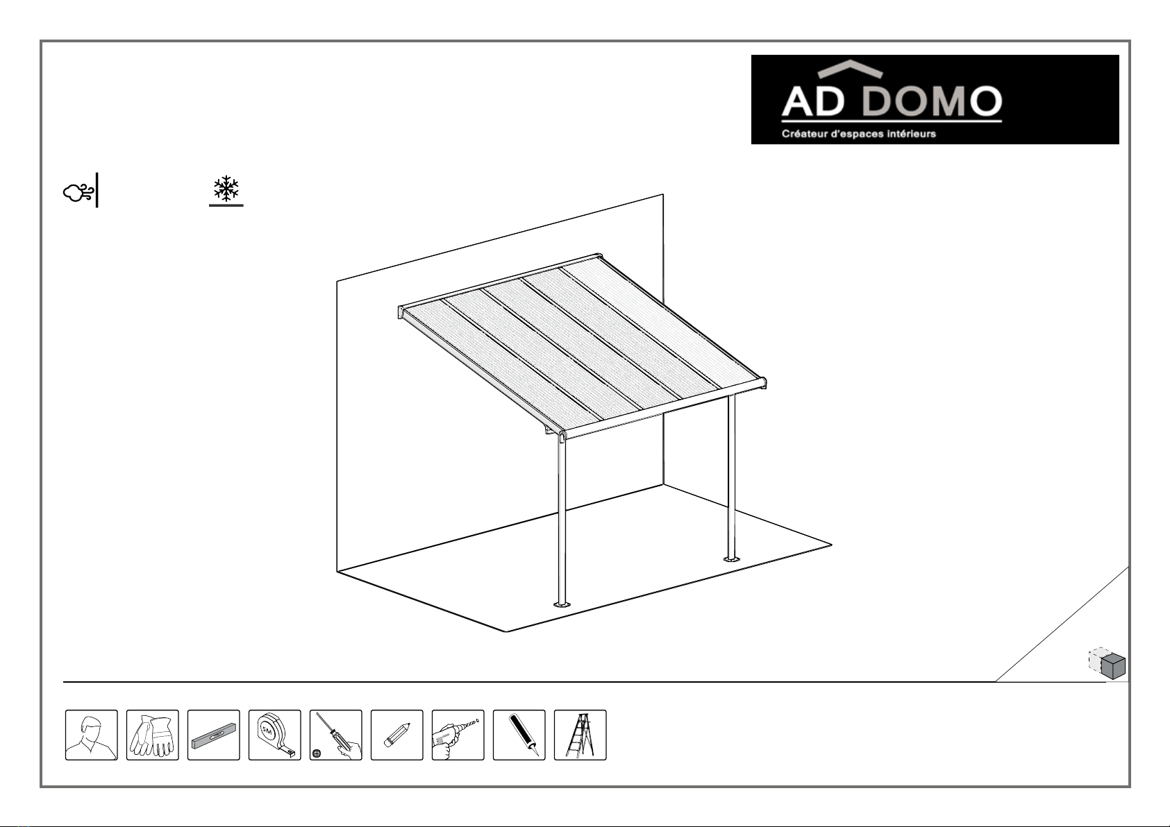
AD DOMO Pergola Elite 3x3 User manual
16.06_83405_V3
x2
Caulk /
Silicon
10mm
13/32”
Snow Load
25lbs/ft
120kg/m
Wind Resistant
120 km/hr
75ml/hr
Approx Dim.
314L x 295W x 260-305H cm / 123.6"L x 116.1"W x 102.3-120"H
RANGE OF
SIZES
Pergola Élite©3x3
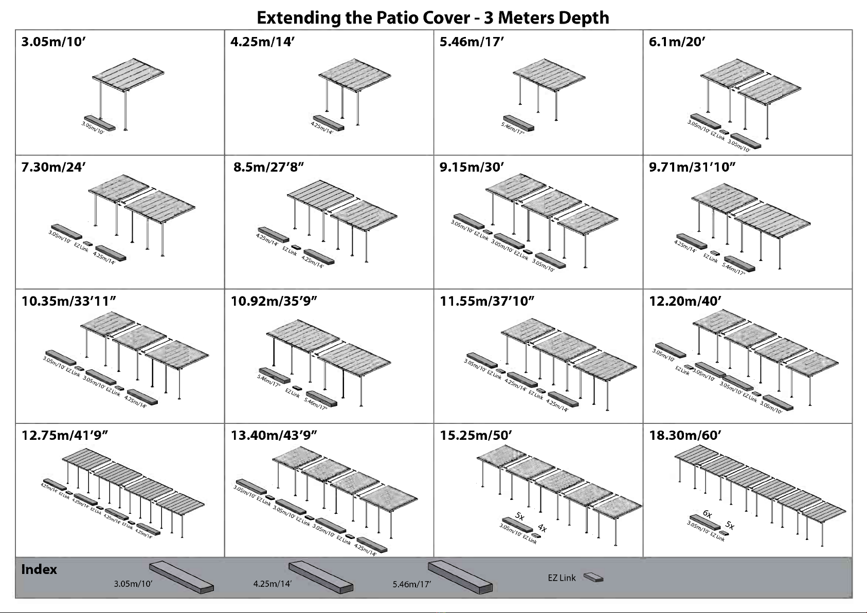
Extending the Patio Cover - 3 Meters Depth
3.05m/10'
7.30m/24'
3
4.25m/14'
8.5m/27'8"
5.46m/17' 6.1m/20'
10.35m/33'11"
3
10.92m/35'9"
12.75m/41'9" 13.40m/43'9"
9.71m/31'10"
11.55m/37'10" 12.20m/40'
15.25m/50' 18.30m/60'
Index 5.46m/17N4' EZ Link 111
Ligne service apres-vente
Phone: 01-34-07-99-00
Fax: 01-34-07-99-19
www.chalet-jardin.com

go
Please read these instructions carefully before you start to
assemble this product.
Please carry out the steps in the order set out in these instructions.
Keep these instructions in a safe place for future reference.
P When encountering the information icon, please refer to the relevant
assembly step for additional comments and assistance.
...:are and Safety Advice
Please follow the instructions as listed in this manual.
Having purchased a long patio cover, make sure you received all boxes according
to the additional page (Extending your patio cover) on the instruction manual.
As soon as you are ready to assemble your patio cover (you can start with this
box), sort the parts and check in accordance with the content list
For safety purposes we strongly recommend the product to be assembled
by at least two people.
Some parts may have sharp edges. Please be careful when handling components.
Always wear gloves, eye protection, and long sleeves when assembling or
performing any maintenance on your product.
Do not attempt to assemble the product in windyor wet conditions.
Dispose ofall plastic bags safely -keep them out of reach of small children.
Keep children away from theassembly area.
Do not attempt to assemble the product if you are tired, have taken drugs,
medications or alcohol, or ifyou are prone to dizzy spells.
When using a stepladder or power tools, make sure you follow the
manufacturer's safety advice.
Do not climb or stand on the roof.
Heavy articles should not be leaned against the poles.
Do not hang or lay on the profiles.
Keep roof and gutter clear of snow, dirt & leaves.
Heavy snow load on roof can damage the product making it unsafe to stand
below or nearby.
This product was designed and produced to be used as a Patio cover only.
Some versions ofthis product are painted.
Ifcolor was scratched during assembly it can be fixed with the following tints:
White -RAL 9016 Grey -RAL 7012
Cleaning Instructions
When your product needs cleaning, use a mild detergent solution and rinse
with cold clean water.
Do not use acetone, abrasive cleaners, or others special detergents to clean
the panels.
Before Assembly
This product must be assembled on a solid base (such as concrete or asphalt)
and anchored to the ground.
Choose your site carefully before beginning assembly.
Sort the parts and check according to the contents parts list.
Site surface needs to be leveled (mainly below the poles).
Please consult your local authorities if any permits are required prior to
constructing the product.
Prior to enlargingthe Patio Cover, several parts need to be dismantled, it is
recommended to keep them in a safe place for future use.
Note: Use only the parts registered in the content list, some parts may be
surplus.
Tools & Equipment
T001 (Supplied)
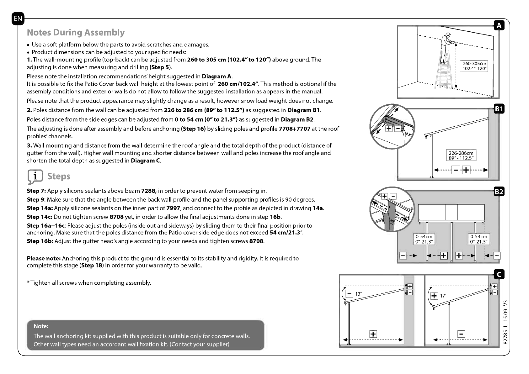
Notes During Assembly
Use a soft platform below the parts to avoid scratches and damages.
Product dimensions can be adjusted to your specific needs:
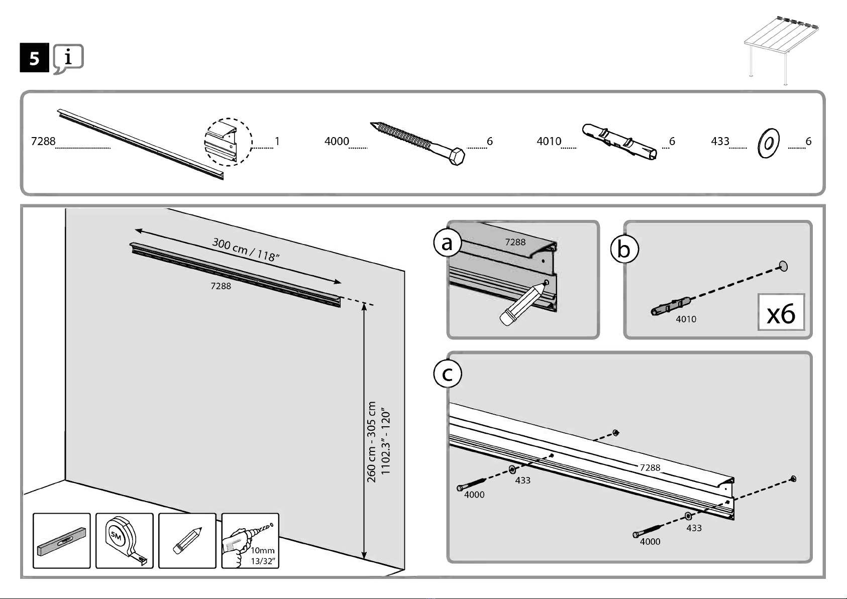
1.The wall-mounting profile (top-back) can be adjusted from 260 to 305 cm (102.4"to 120") above ground. The
adjusting is done when measuring and drilling (Step 5).
Please note the installation recommendations' height suggestedin Diagram A.
It is possible to fix the Patio Cover back wall heightat the lowest point of 260 cm/102.4". This method is optional ifthe
assembly conditions and exterior walls do not allow to follow the suggested installation as appears in the manual.
Please note that the product appearance may slightly change as a result, however snow load weight does not change.
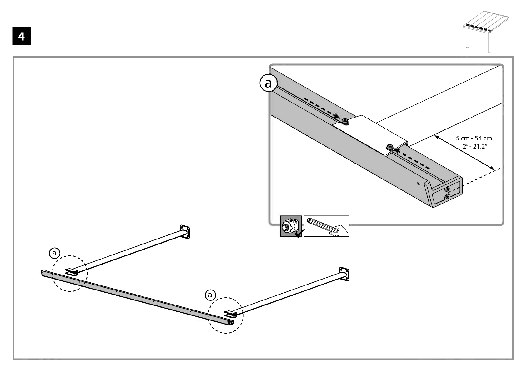
2. Poles distance from the wall can be adjusted from 226 to 286 cm (89" to 112.5") as suggested in Diagram B1.
Poles distance from the side edges can be adjusted from 0 to 54 cm (0" to 21.3") as suggested in Diagram B2.
The adjusting is done after assembly and before anchoring (Step 16) by sliding poles and profile 7708+7707 at the roof
profiles' channels.
3. Wall mounting and distance from the wall determine the roof angle and the total depth of the product (distance of
gutter from the wall). Higher wall mounting and shorter distance between wall and poles increase the roof angle and
shorten the total depth as suggested in Diagram C.
Li] Steps
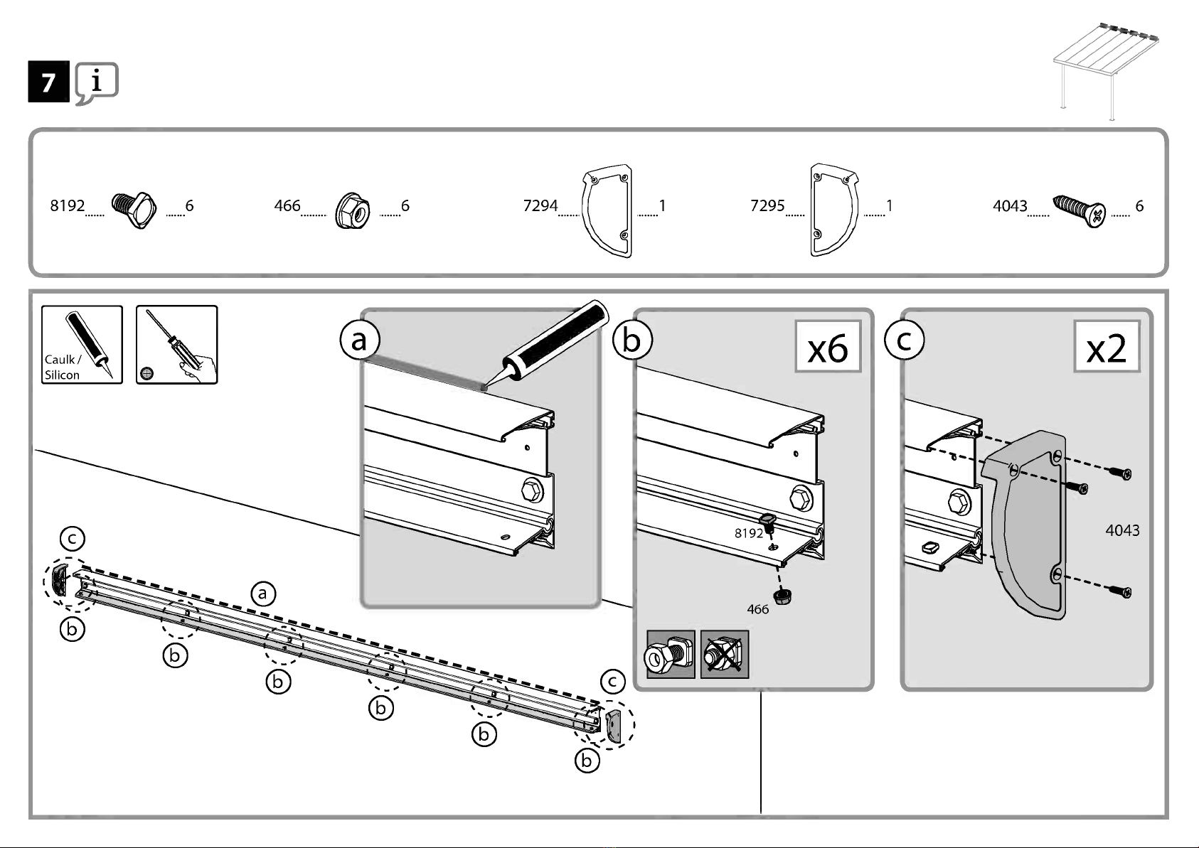
Step 7: Apply silicone sealants above beam 7288, in order to prevent water from seeping in.
Step 9: Make sure that the angle between the back wall profile and the panel supporting profiles is 90 degrees.
Step 14a:Apply silicone sealants on the inner part of7997, and connect to the profile as depicted in drawing 14a.
Step 14c: Do not tighten screw 8708 yet, in order to allow the final adjustments done in step 16b.
Step 16a+1 6c: Please adjust the poles (inside out and sideways) by sliding them to their final position prior to
anchoring. Make sure that the poles distance from the Patio cover side edge does not exceed 54 cm/21.3':
Step 16b: Adjust the gutter head's angle according to your needs and tighten screws 8708.
Please note: Anchoring this product to the ground is essential to its stability and rigidity. It is required to
complete this stage (Step 18) in order for your warranty to be valid.
*Tighten all screws when completing assembly.
Note:
The wall anchoring kit supplied with this product is suitable only for concrete walls.
Other wall types need an accordant wall fixation kit. (Contact your supplier)
II
260-305cm
102.4"-120"
0-54cm
0'-21.3"
.
I
.
- 13° . + 17°
*; ..
+ -
f i -411-
P
Lire attentivement ces instructions avant de commencer le montage de ce toit
de terrasse. Suivez bien les etapes indiquees dans l'ordre indique.
Conservezce mode d'emploi dans un endroit sOr pour reference ulterieure.
Lorsque vous rencontrez !lame information, merci de vous referez a l'etape
d'assemblage appropriee pourtoute remarque et assistance additionnelle.
Aecommandations d'entretien et de securite
Suivez les instructions dans l'ordre indique dans ce manuel.
Vous venez d'acheter un grand abri de terrasse, veuillez vous assurer que vous
avez recu toutes les boites mentionnees dans la page additionnelle du manuel
d'instruction (Extension de votre abri de terrasse).
Des que vous etes pret a assembler votre abri de terrasse (vous pouvez
commencer avec cette boite), triez les pieces et verifiez le contenu indique dans
la liste des elements.
Verifiez que le paquet contient bien toutes les pieces.
Pour des raisons de securite, nous recommandons vivement que le produit soit
assemble par deux personnes au minimum.
Certaines pieces comportent des aretes en metal. Soyez prudent en manipulant
les pieces.
Toujours porter des gants, des chaussures et des lunettes de securite pendant le
montage.
N'essayez pas de proceder au montage s'il y a du vent ou s'il pleut.
Se defaire de tous les emballages en plastique en veillant a ne pas les laisser
a la portee des enfants.
Eloignez les enfants du site de montage.
N'essayez pas de monter le produit si vous etes fatigue, si vous avez pris des
medicaments ayant un effet sur votre etat d'eveil, des drogues ou si vous avez
bu de l'alcool, ni si vous etes sujet a des vertiges.
Lorsque vous utilisez une echelle ou des outils electriques,veilleza suivre
le mode d'emploi et les conseils de securite du fabricant des appareils.
Ne pas grimper ni se tenir sur le toit.
Ne pas adosser des objets lourds contre les poteaux.
Ne pas accrocher ou poser des objets sur les profils.
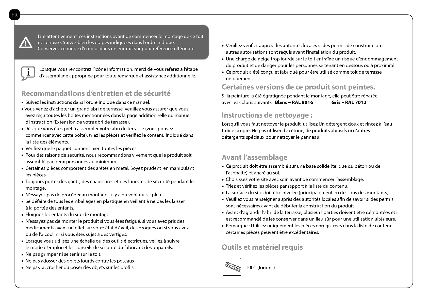
Veuillez verifier aupres des autorites locales si des permis de construire ou
autres autorisations sont requis avant ('installation du produit.
Une charge de neige trop lourde sur le toit entraine un risque d'endommagement
du produit et de danger pour les personnes se tenant en dessous ou a proximite.
Ce produit a ete concu et fabrique pour etre utilise comme toit de terrasse
uniquement.
Certaines v,......,.... My r, Oda'. 31....... ro.........C3.
Si la peinture a ete egratignee pendant le montage, elle peut etre reparee
avec les coloris suivants: Blanc -RAL 9016 Gris - RAL 7012
Instructions de nettoyagP
Lorsqu'il vous faut nettoyer le produit, utilisez Un detergent doux et rincez a l'eau
froide propre. Ne pas utiliser d'acetone,de produits abrasifs ni d'autres
detergents speciaux pour nettoyer le panneau.
Avant ('assemblage
Ce produit doit etre assemble sur une base solide (tel que du beton ou de
l'asphalte) et ancre au sol.
Choisissez votre site avec soin avant de commencer ('assemblage.
Triez et verifiez les pieces par rapport a la liste du contenu.
La surface du site doit etre nivelee (principalement en dessous des montants).
Veuillez vous renseigner aupres des autorites locales afin de savoir si des permis
sont necessaires avant de debuter la construction du produit.
Avant d'agrandir l'abri de la terrasse, plusieurs parties doivent etre demontees et it
est recommande de les conserver dans un lieu sOr pour une utilisation ulterieure.
Remarque : Utilisez uniquement les pieces enregistrees dans la liste de contenu,
certaines pieces peuvent etre excedentaires.
Outils et materiel requis
T001 (fournis)

Remarques a prendre en cornpte pendant ('assemblage
Servez-vous d'un support en nnatiere souple en dessous des pieces afin d'eviter les risques d'egratignures ou d'autres dommages.
Les dimensions du produit sont ajustables en fonction de vos besoins particuliers :
1. Le profile de raccordement de paroi (superieur-arriere) est ajustable de 260 a 305 cm (102,4 a 120 po.) au-dessus du sol.
Cet ajustement s'effectue au moment de la prise de mesures et du percage (etape 5).
Veuillez prendre note de la hauteur d'installation conseilleeindiquee dans le Schema A. On peut fixer la hauteur de la paroi arriere du
toit de terrasse au point le plus bas, a 260 cm/102,4 po. Cette nnethode est optionnelle si les conditions d'assemblage et les parois
exterieures ne permettent pas de suivre ('installation suggeree telle qu'elle est presentee dans le manuel.
Veuillez noter que ('aspect du produit peut etre legerennent nnodifie en consequence, mais que la charge de neige autorisee
reste la nnenne.
2. La distance des montants par rapport a la paroi est ajustable de 226 a 286 cm (89 a 112,5 po.), comme indique dans le Schema B1.
La distance des montants par rapportaux bords des cotes est ajustable de 0 a 54 cm (0 a 21,3 po.), comme indique dans le Schema B2.
Ces ajustements s'effectuent apres ('assemblage et avant l'ancrage (etape 16), en faisant glisser les montants et les profiles
1041 sur les rails de profiles du toit.
3. Le raccordement a la paroi et la distance par rapport a celle-ci deternninent l'angle du toit et la profondeur totale du produit
(distance de la gouttiere par rapport a la paroi). Un raccordement plus eleve sur la paroi et une distance plus courte entre la paroi
et les montants augmenteront l'angle du toit et reduiront la profondeur totale, comme nnontre dans le Schema C.
Etapes :
Etape 7: Appliquez les joints en silicone au-dessus de la poutre 7288 + 7290 afin d'empecher l'eau d'y penetrer.
Etape 9: Verifiez que l'angle entre la paroi arriere et les parois de soutenement soit bien de 90 degres.
Etape 14a:Appliquez les joints en silicone sur la face interne de 7797 et raccordez-le a la paroi, comme vous le
voyez sur ('illustration 14a.
Etape 14c: Ne serrez pas encore la vis 8708, car cela nous empecherait d'effectuerles derniers ajustements
decrits a l'etape 16b.
Etapes 16a et 16c: Ajustez les perches (a l'interieur et sur les cotes) en les faisant glisser vers leur position
finale avant de les fixer. Assurez-vous bien du fait que la distance entre les perches et le bord du toit du patio ne
depasse pas 54 cm.
Etape 16b: Ajustez l'angle de la bouche de la gouttiere en fonction de vos besoins, puis serrez la vis 8708.
Remarque: II est necessaire d'ancrer ce produit dans le sol afin d'assurer sa stabilite et sa rigidite.Votre garantie
ne peut s'appliquertant que vous n'avez pas effectue cette etape (etape 18).
* Serrez toutes les vis a la fin de ('assemblage.
Remarque :
Le kit de fixation murale fourni avec ce produit est uniquement compatible avec le beton.
Dautres types de mur necessitent un kit de fixation different et compatible (contactez votre fournisseur)
II
260-305cm
102.4"-120"
a
. .
- 13° . + 17°
.. ,
+ -
f i -41-
m
1
7

Bite lesen Sie diese Hinweise sorgfaltig, bevor Sie mit der Montage dieses Patio-
Abdeckungsystems starten.
Bitte fuhren Sie die Schritte in der Reihenfolge aus, wie sie in dieser Anleitung
vorgegeben sind. Bewahren Sie diese Anleitung an einem sicheren Ort auf.
Beim Aufbau wird Ihnen das Informationssymbol begegnen.
Fur zusatzliche Kommentare und Unterstitzung beziehen Sie sich bitte auf
die entsprechende Aufbaustufe.
..)flege und SicherheitshinweisP
Bitte folgen Sie die in diesem Handbuch aufgefuhrten Anweisungen.
Achten Sie bitte nach Ihrem Kauf der langen Terrassen-Abdeckung darauf, dass Sie
alle Boxen gemaB der zusatzlichen Seite der Anleitung (Verlangerung IhrerTerrassen-
Abdeckung) erhalten haben.
Sobald Sie bereft sind, Ihre Terrassen-Abdeckung zu installieren (Sie !carmen mit dieser
Box anfangen), sortieren Sie die Teile und Ciberpriden Sie, ob sie mit der Inhaltsliste
übereinstimmen.
Sortieren Sie die Teile und Ciberpriden Sie die Inhaltsliste.
Aus Sicherheitsgrunden empfehlen wir dringend, dass das Produkt von mindestens zwei
Menschen zusammengebaut wird.
EinigeTeile haben Metallkanten. Bitte seien Sie vorsichtig beim Umgang mit den Komponenten.
Tragen Sie immer Handschuhe, Schuhe und Schutzbrille bei der Montage.
Versuchen Sie nicht, das Produkt bei windigen oder nassen Bedingungen zu montieren.
Entsorgen Sie alle Plastiktuten sicherheitsgemaB - bewahren Sie sie auBerhalb der
Reichweite von kleinen Kindern auf.
Halten Sie Kinder vom Montagebereich fern.
Versuchen Sie nicht ein Produkt zusammen zu bauen, wenn Sie mude sind, Drogen,
Medikamente oder Alkohol genommen haben, oder wenn Sie zu Schwindelanfallen neigen.
Bei Verwendung einer Stehleiter oder Elektrowerkzeugen, stellen Sie sicher,
dass Sie die Sicherheitshin weise und Anweisungen des Herstellers befolgen.
Steigen oder stehen Sie nicht aufdem Dach.
Schwere Gegenstande durfen nicht an den Polen angelehntwerden.
Hangen Sie sich nicht an die Profile.
Halten Sie Dach - und Dachrinne frei von Schnee, Schmutz und Blattern.
Schwere Schneelasten auf dem Dach !carmen das Produkt beschadigen und das Darunter-
oder Danebenstehen gefahrlich machen.
Dieses Produkt wurde einzig und allein alsTerrassenuberdachung entworfen und
produziert.
Einige Versionen dieses Produkts sind lackiert. Solite die Farbe bei der Montage
verkratzten, kann es mit den folgenden Farben nachlackiert werden:
Weiss - RAL 9016 Grau - RAL 7012
Pflegeanleitung
Wenn Sie Ihr Produkt reinigten mussen, verwenden Sie ein mildes
Reinigungsmittel und reinigen Sie mit kaltem Wasser.
Verwenden Sie kein Aceton, Scheuermittel oder .
Vor dem Aufbau
Dieses Produkt muss aufeinem stabilen Untergrund aufgebaut werden (wie
Beton oder Asphalt).
Wahlen Sie Ihren Standort sorgfaltig, bevorSie mit dem Aufbau beginnen.
Sortieren Sie die einzelnen Teile und gleichen Sie sie mit der Inhaltsliste ab.
Die Aufbauflache muss geebnetwerden (vor allem unter den Pfosten.
Bitte informieren Sie sich bei den ortlichen Behorden, ob fur den Aufbau des
Produktes eine Genehmigung erforderlich ist.
Vor der Erweiterung der Terrassen-Abdeckung mussen mehrere Teile
auseinander gebautwerden, es empfiehlt sich sie fur den spateren Gebrauch
an einem sicheren Ort aufbewahren.
Hinweis:Verwenden Sie nur die in der Inhaltsliste eingetragenen Teile, einige
Teile !carmen Ciberflussig sein.
Werkzeug & Ausrustung
Tool - (Werkzeuge)
viVahrend des Aufbaus
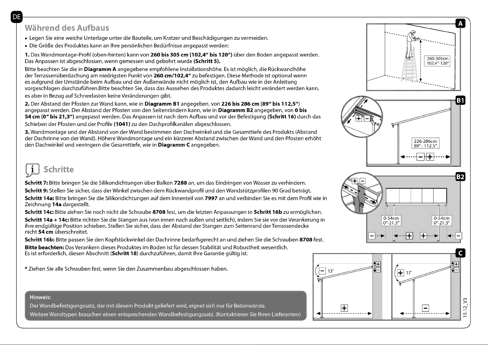
Legen Sie eine weiche Unterlage unter die Bauteile, urn Kratzer und Beschadigungen zu vermeiden.
Die Gra Be des Produktes kann an Ihre personlichen Bedurfnisse angepasst werden:
1. DasWandmontage-Profil (oben-hinten) kann von 260 bis 305 cm (102,4" bis 120") Ober den Boden angepasst werden.
Das Anpassen ist abgeschlossen, wenn gemessen und gebohrt wurde (Schritt 5).
Bitte beachten Sie die in Diagramm A angegebene empfohlene Installationshohe. Es ist moglich, die Ruckwandhohe
der TerrassenOberdachung am niedrigsten Punkt von 260 cm/102,4" zu befestigen. Diese Methode ist optional wenn
es aufgrund der Umstande beim Aufbau und der AuBenwande nicht moglich ist, den Aufbau wie in der Anleitung
vorgeschlagen durchzufOhren.Bitte beachten Sie, dass das Aussehen des Produktes dadurch leicht verandert werden kann,
es aber in Bezug aufSchneelasten keine Veranderungen gibt.
2. Der Abstand der Pfosten zur Wand kann, wie in Diagramm B1 angegeben, von 226 bis 286 cm (89" bis 112,5")
angepasst werden. Der Abstand der Pfosten von den Seitenrandern kann, wie in Diagramm B2 angegeben, von 0 bis
54 cm (0" bis 21,3") angepasst werden. Das Anpassen ist nach dem Aufbau und vor der Befestigung (Schritt 16) durch das
Schieben der Pfosten und der Profile (1041) zu den Dachprofilkanalen abgeschlossen.
3. Wandmontage und der Abstand von der Wand bestimmen den Dachwinkel und die Gesamttiefe des Produkts (Abstand
der Dachrinne von der Wand). Flohere Wandmontage und ein kurzerer Abstand zwischen der Wand und den Pfosten erhoht
den Dachwinkel und verringern die Gesamttiefe, wie in Diagramm C angegeben.
Schrittc
Schritt 7: Bitte bringen Sie die Silikondichtungen Ober Balken 7288 an, urn das Eindringen von Wasser zu verhindern.
Schritt 9: Stellen Sie sicher, dass der Winkel zwischen dem Ruckwandprofil und den Wandstutzprofilen 90 Grad betragt.
Schritt 14a: Bitte bringen Sie die Silikondichtungen auf dem Innenteil von 7997 an und verbinden Sie es mit dem Profil wie in
Zeichnung 14a dargestellt.
Schritt 14c: Bitte ziehen Sie noch nicht die Schraube 8708 fest, urn die letzten Anpassungen in Schritt 16b zu ermoglichen.
Schritt 14a + 14c: Bitte richten Sie die Stangen aus (von innen nach auBen und seitlich), indem Sie sie vor derVerankerung in
ihre endgultige Position schieben. Stellen Sie sicher, dass der Abstand der Stangen zum Seitenrand der Terrassendecke
nicht 54 cm Oberschreitet.
Schritt 16b: Bitte passen Sie den KopfstOckwinkel der Dachrinne bedarfsgerecht an und ziehen Sie die Schrauben 8708 fest.
Bitte beachten: Das Verankern dieses Produktes im Boden ist fur dessen Stabilitat und Robustheit wesentlich.
Es ist erforderlich, diesen Abschnitt (Schritt 18) durchzufuhren, damit Ihre Garantie gultig ist.
* Ziehen Sie alle Schrauben fest, wenn Sie den Zusammenbau abgeschlossen haben.
Hinwei s:
Der Wandbefestigungssatz, der mit diesem Produkt geliefert wird, eignet sich nur fur Betonwande.
WeitereWandtypen brauchen einen entsprechenden Wandbefestigungssatz. (Kontaktieren Sie Ihren Lieferanten)
II 260-305cm
102.4"-120"
a
13°
EH
-13
17°
GP
P
Pfedtim, nee zat'nete terasovou stfechu sestavovat, si pedive pfeaete tyto pokyny.
Provadejte jednotlive kroky v pofadiuvedenem v techto pokynech.
Uchovavejte tyto pokyny pro daRipotfebu na bezpet'nem mist&
Kdy2 narazite na informaC'nfikonu, podivejte se prosim na
pifsluSny montaZni krok na dopinujici komentate a rady.
Pokyny pro peel a bezpecnost
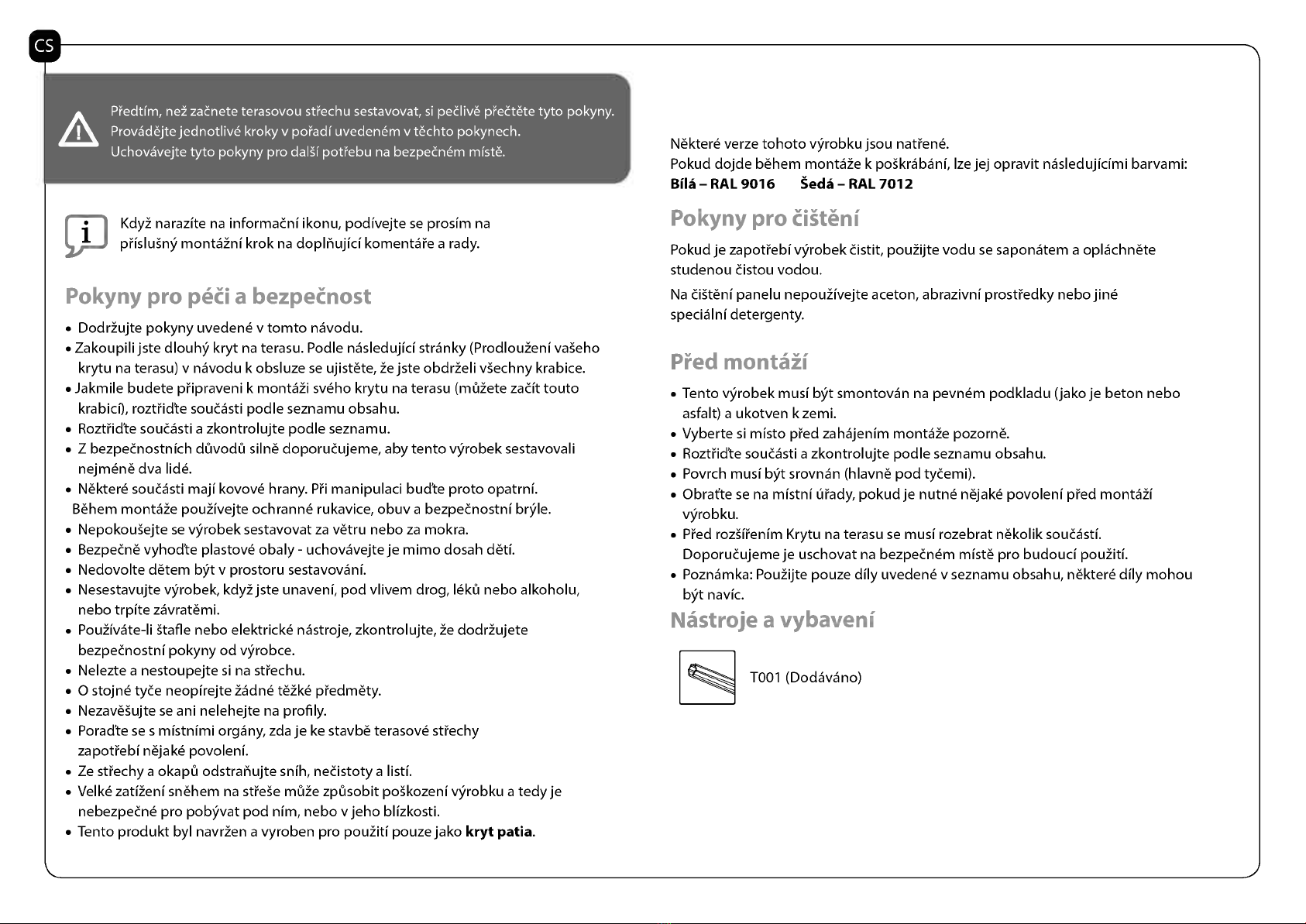
DodrZujte pokyny uvedene v tomto navodu.
Zakoupili jste dlouhy kryt na terasu. Podle nasledujici stranky (ProdlouZenivaSeho
krytu na terasu) v navodu k obsluze se ujistete, Ze jste obdrZeli vSechny krabice.
Jakmile budete piipraveni k montaZi sveho krytu na terasu (mOZete zadt touto
krabici), rortiidte souC'asti podle seznamu obsahu.
Rortiidte souC'asti a zkontrolujte podle seznamu.
Z bezpeC'nostnich dOvodO silne doporuC'ujeme, aby tento vyrobek sestavovali
nejmene dva lide.
Nektere souC'asti maji kovove hrany. Pii manipulaci bud'te proto opatrni.
Behem montane pouZivejte ochranne rukavice, ()buy a bezpeC'nostni bryle.
NepokouSejte se vyrobek sestavovat za vetru nebo za mokra.
BezpeC'ne vyhod'te plastove obaly - uchovavejte je mimo dosah &ed.
Nedovolte detem byt v prostoru sestavoyani.
Nesestavujte vyrobek, kdy2 jste unaveni, pod vlivem drog, lekO nebo alkoholu,
nebo trpite zavratemi.
PouZivate-li Stafle nebo elektricke nastroje, zkontrolujte, Ze dodrZujete
bezpeC'nostni pokyny od vyrobce.
Nelezte a nestoupejte si na stiechu.
0 stojne tyC'e neopirejte Zadne teZke piedmety.
NezaveSujte se ani nelehejte na profily.
Porad'te se s mistnimi organy, zda je ke stavbe terasove stiechy
zapotiebi nejake povoleni.
Ze stiechy a okapO odstranujte snih, nedstoty a listi.
Velke zatiZeni snehem na stieSe mute zpOsobit poSkozeni vyrobku a tedy je
nebezpeC'ne pro pobyvat pod nim, nebo v jeho blizkosti.
Tento produkt byl navrZen a vyroben pro pouZiti pouze jako kryt patia.
Nektere verze tohoto vyrobku jsou natiene.
Pokud dojde behem montane k poSkrabanf, lze jej opravit nasledujicimi barvami:
BHA - RAL 9016 'ecla - RAL 7012
I ...mylly vIJeigtehol
Pokud je zapotiebi vyrobek C'istit, pouZijte vodu se saponatem a oplachnete
studenou C'istou vodou.
Na C'iSteni panelu nepouZivejte aceton, abrazivni prostiedky nebo jine
specialni detergenty.
1)1.-..4 ...allLail
Tento vyrobek musi byt smontovan na pevnem podkladu (jako je beton nebo
asfalt) a ukotven k zemi.
Vyberte si mist° pied zahajenim montane pozorne.
Rortiidte souC'asti a zkontrolujte podle seznamu obsahu.
Povrch musi byt srovnan (hlavne pod tyC'emi).
Obrafte se na mistni iliady, pokudje nutne nejake povoleni pied monta21
vyrobku.
Pied rozSitenim Krytu na terasu se musi rozebrat nekolik souC'astf.
DoporuC'ujeme je uschovat na bezpeC'nem miste pro budouci pouZiti.
Poznamka: PouZijte pouze dily uvedene v seznamu obsahu, nektere dily mohou
byt navic.
Nastroje a vyL,veni
T001 (Dodavano)
Poznamky k montaii
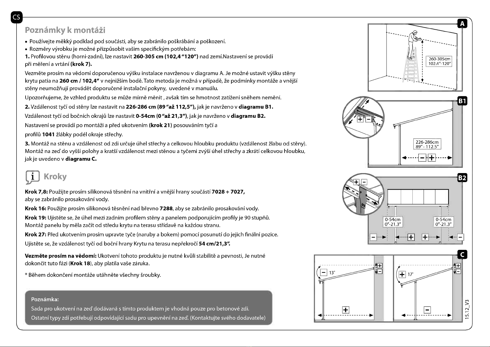
PouZivejte mekky podklad pod souC'asti, aby se zabranilo poSkrabanf a poSkozeni.
Rozmery vrobkuje moZne ptizpOsobit vaSim specifickm pottebam:
1. Profilovou stenu (horni-zadni), Ize nastavit 260-305 cm (102,4"120") nad zemi.Nastaveni se provadf
pti metenfa vrtanf (krok7).
Vezmete prosim na vedomf doporuC'enou v)/Sku instalace navrZenou v diagramu A. Je moZne ustavit v)/Sku steny
krytu patia na 260 cm / 102,4" v nejni2Sim bode.Tato metoda je moZna v ptipade, Ze podminky montane a vnejS1
steny neumoZnuji provadet doporuC'ene instalaC'nfpokyny, uvedene v manualu.
Upozornujeme, Ze vzhled produktu se mute mime menit , avSak dm se hmotnost zatiZeni snehem nemenf.
2. Vzdalenost tya od steny Ize nastavit na 226-286 cm (89"ai 112,5"), jakje navrZeno v diagramu B1.
Vzdalenost tyd od boC'nich okrajO Ize nastavit 0-54cm (0 "ai21,3"), jakje navrZeno v diagramu B2.
Nastaveni se provadf po montaZi a pied ukotvenim (krok21) posouvanim tyd a
profil0 1041 21abky podel okraje stiechy.
3. Monta2 na stenu a vzdalenost od zdi urC'uje Uhel stiechy a celkovou hloubku produktu (vzdalenost 21abu od steny).
Monta2 na zed'do vySS1polohy a kratSfvzdalenost mezi stenou a tyC'emi zqSfilhel stiechy a zkratf celkovou hloubku,
jakje uvedeno v diagramu C.
Kroky
Krok 7,8: PouZijte prosim silikonova tesneni na vnitini a vnejSihrany souC'asti 7028 + 7027,
aby se zabranilo prosakovanf vody.
Krok 16: PouZijte prosim silikonova tesneni nad btevno 7288, aby se zabranilo prosakovanivody.
Krok 19: Ujistete se, Ze Uhel mezi zadnim profilem steny a panelem podporujicim profilyje 90 stuphO.
Monta2 panelu by mela zadt od sttedu krytu na terasu stifdave na kaZdou stranu.
Krok 27: Pied ukotvenim prosim upravte tyC'e (naruby a bokem) pomoci posunuti dojejich finalni pozice.
Ujistete se, Ze vzdalenost tyd od boC'nihrany Krytu na terasu neptekrod54 cm/21,3".
Vezmete prosim na vedomf: Ukotveni tohoto produktu je nutne kvOli stabilite a pevnosti, Je nutne
dokondt tuto fazi (Krok 18), aby platila vase zaruka.
* Behem dokonC'eni montane utahnete vSechny.Sroubky.
Poznamka:
Sada pro ukotveni na zed'dodavana s timto produktem je vhodna pouze pro betonove zdi.
Ostatni typy zdi pottebuji odpovidajici sadu pro upevneni na zed. (Kontaktujte sveho dodavatele)
II
260-305cm
102.4"-120"
0 54cm
0"-21.3" 0 54cm
0'-21.3"
.
. .
- 1 3°
. + 17°
..
+ -
f i -41-
m
1
cv
LE,
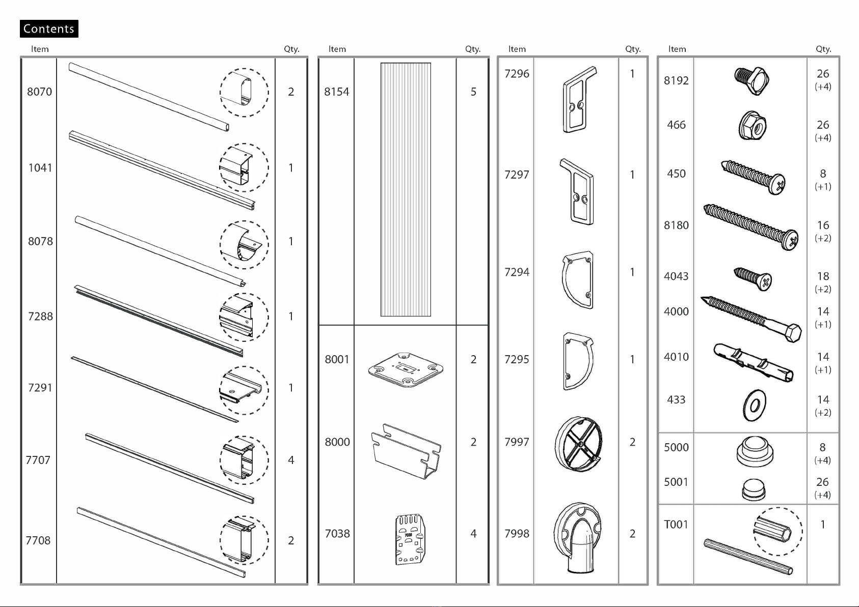
Contents
Item
8070
1041
8078
7288
7291
7707
7708
Qty. Item Qty. Item
8154 5
8001
8000
7038
2
2
4
7296
7297
7294
7295
7997
7998
Qty. Item
8192
466
450
8180
4043
4000
4010
433
5000
5001
TO01
Qty.
26(+4)
26(+4)
8(+1)
16(+2)
18(+2)
14(+1)
14(+1)
14(+2)
8(+4)
26(+4)
1
1
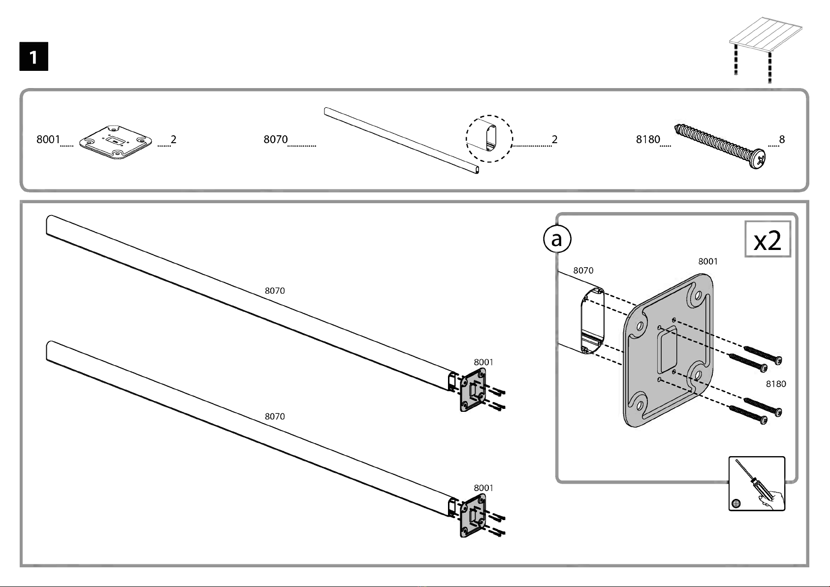
8001 2 8070 2 8180 8
_.4
2
r
L
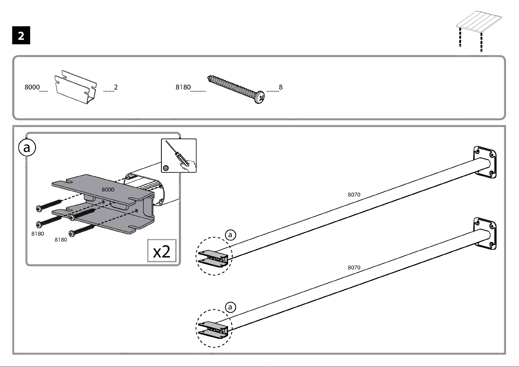
8000 2 8
4
., .......0
5
r ,
L
7288 4000 6 4010 6 433 ® 6
L
.10
a
.0.
.0.
0..
40.
f0"19°4010 I x6
,-o

6
7291 rr
-M
II
Elk
0
7
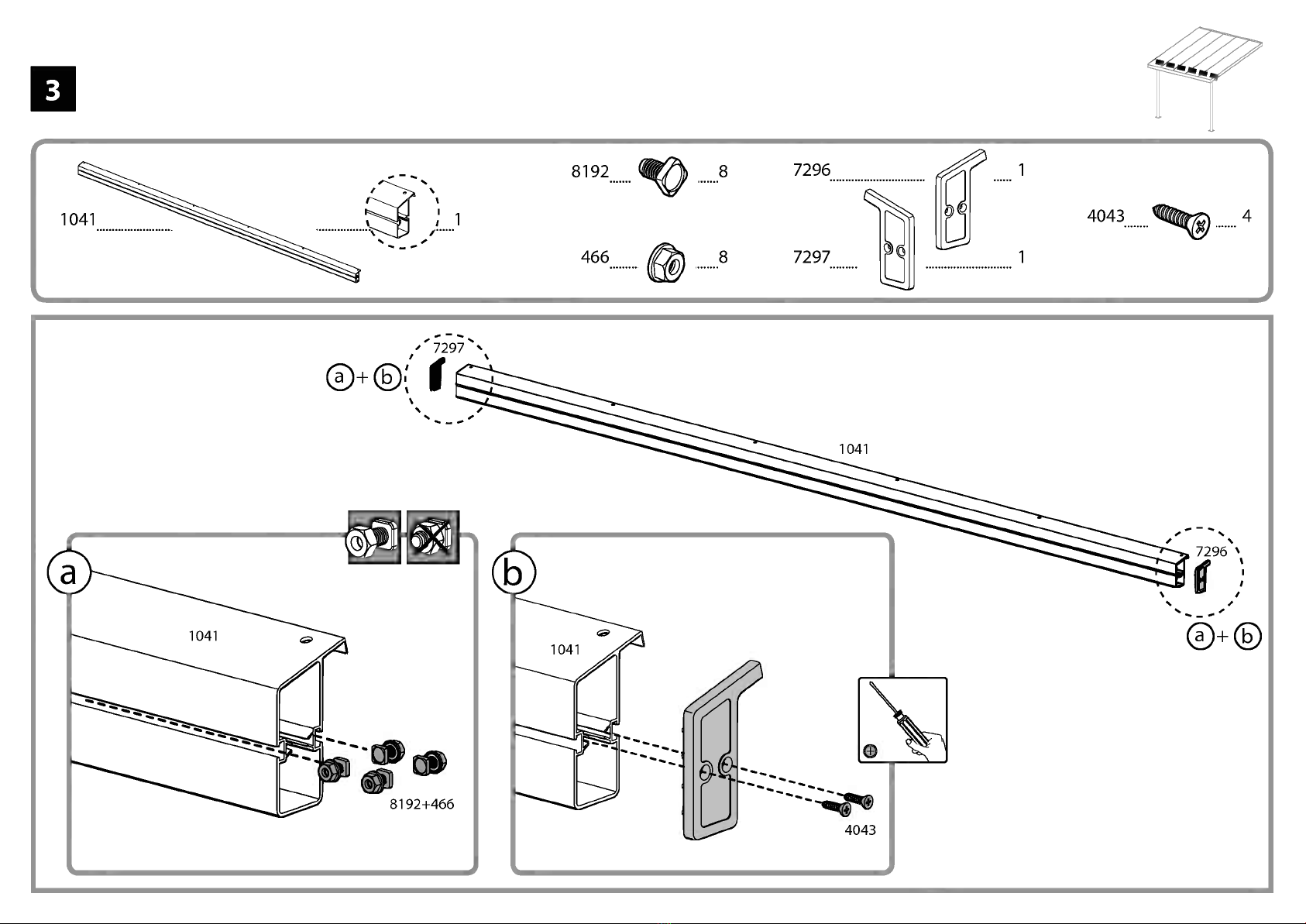
8192 6 466 6 7294 1 7295 1 4043 6

8
1 8192 1 466 1
This manual suits for next models
1


