Adam Hall STAGELIFT 150 User manual
USER´S MANUAL
BEDIENUNGSANLEITUNG
MANUEL D`UTILISATION
MANUAL DE USUARIO
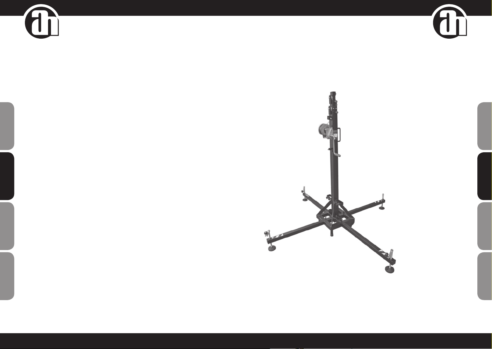
STAGELIFT150
LIFTING TOWER

2 3
ENGLISH
ENGLISH
DEUTSCH
DEUTSCH
FRANCAISFRANCAIS
FRANCAISFRANCAIS FRANCAISFRANCAIS
FRANCAISFRANCAIS FRANCAISESPAÑOL
FRANCAISESPAÑOL
STAGELIFT150
LIFTING TOWER
1. INTRODUCTION
This instruction manual has been drafted pursuant Machinery Directive CE 2006/42/EG requisites.
The instruction manual is an integral part of the lifting tower and is to be consulted before, during and after
tower startup, likewise whenever deemed necessary, respecting the contents for each and all the parts
thereof.
This is the only way to achieve the basic objectives established in the manual base such as preventing accident
risks and maximum optimisation possible for the lifting tower features.
This manual has taken extreme care regarding safety and accident prevention at work while using this product
highlighting information of particular interest to the user.
ATTENTION: PRIOR TO USING THE LIFTING TOWER, READ THIS MANUAL CAREFULLY
2. GENERAL DATA
2.1. TECHNICAL DATA
NAME Stagelift
MODEL Stagelift 150
TECHNICAL CHARACTERISTICS Maximum height: 5,30 m
Minimum height: 1,73 m
Maximum load: 150 kg
Minimum load: 25 kg
Material: Steel as per DIN 2394
Open base area: 1,90 x 1,90 m
Closed base area: 0,38 x 0,38 m
Weight: 48 kg
Winch: 450 kg maximum load with automatic load retention
brake
Cable: Galvanized steel under EN12385-4. Right hand ordinary lay
MaxLoad: 9375N
Tensile strength: 1770N /mm². Diameter: 4 mm. Length: 9 m
Fixation of tower sections to working height with safety pins.
Leg anchorage with safety pins.
Bubble level to adjust tower vertical position.
Rustproof protection and painting protection nish.
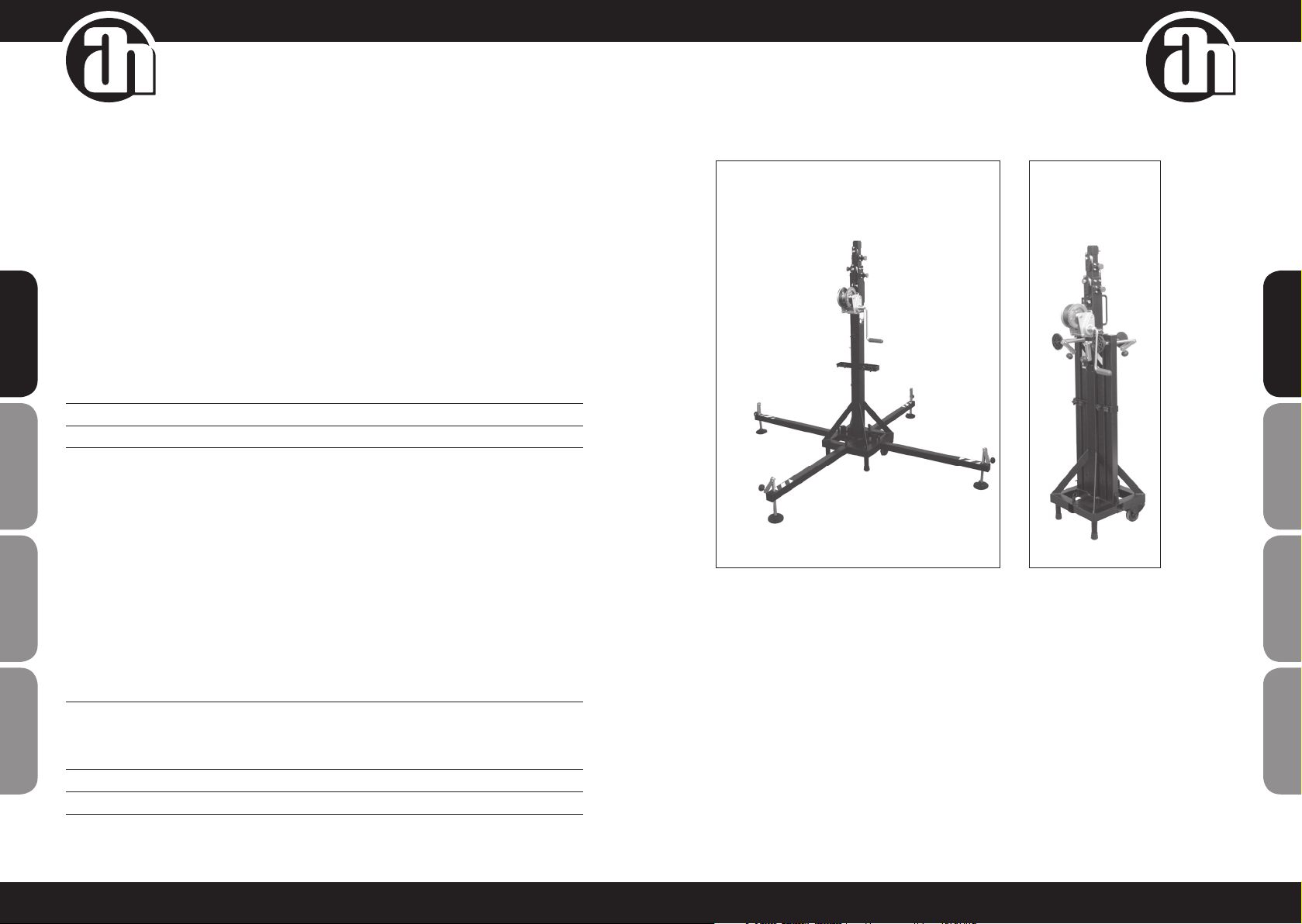
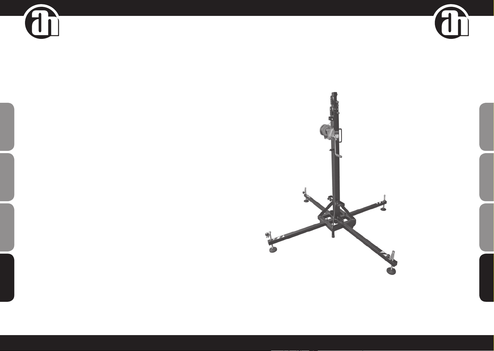
EQUIPMENT DESCRIPTION Lifting tower Stagelift 150 has been designed to vertically raise
structures and lighting and sound equipment to different heights.
Tested by skilled personnel having passed all the operating,
maximum load and dimension inspections.
COMPANY Adam Hall GmbH
ADDRESS Daimlerstrasse 9 ∙ 61267 Neu-Anspach ∙ Germany
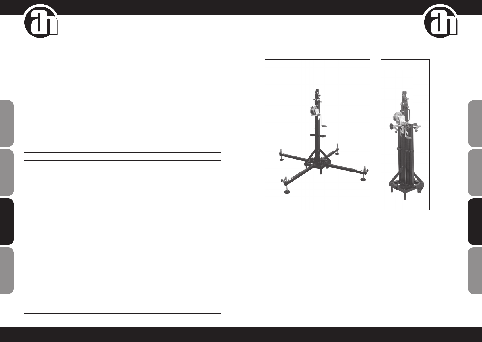
PICTURES
2.2. APPLICABLE REGULATIONS
• DIRECTIVES CE 2006/42/EG ON MACHINERY
• BGV C1 (GUV 6.175)
• BGG 912 (GUV 66.15, GUV G-912)
• EN 12385-4:2008-06
• DIN EN 10305-3:2010-05
4 5
ENGLISH
ENGLISH
DEUTSCH
DEUTSCH
FRANCAISFRANCAIS
FRANCAISFRANCAIS FRANCAISFRANCAIS
FRANCAISFRANCAIS FRANCAISESPAÑOL
FRANCAISESPAÑOL
3. GENERAL SAFETY RULES
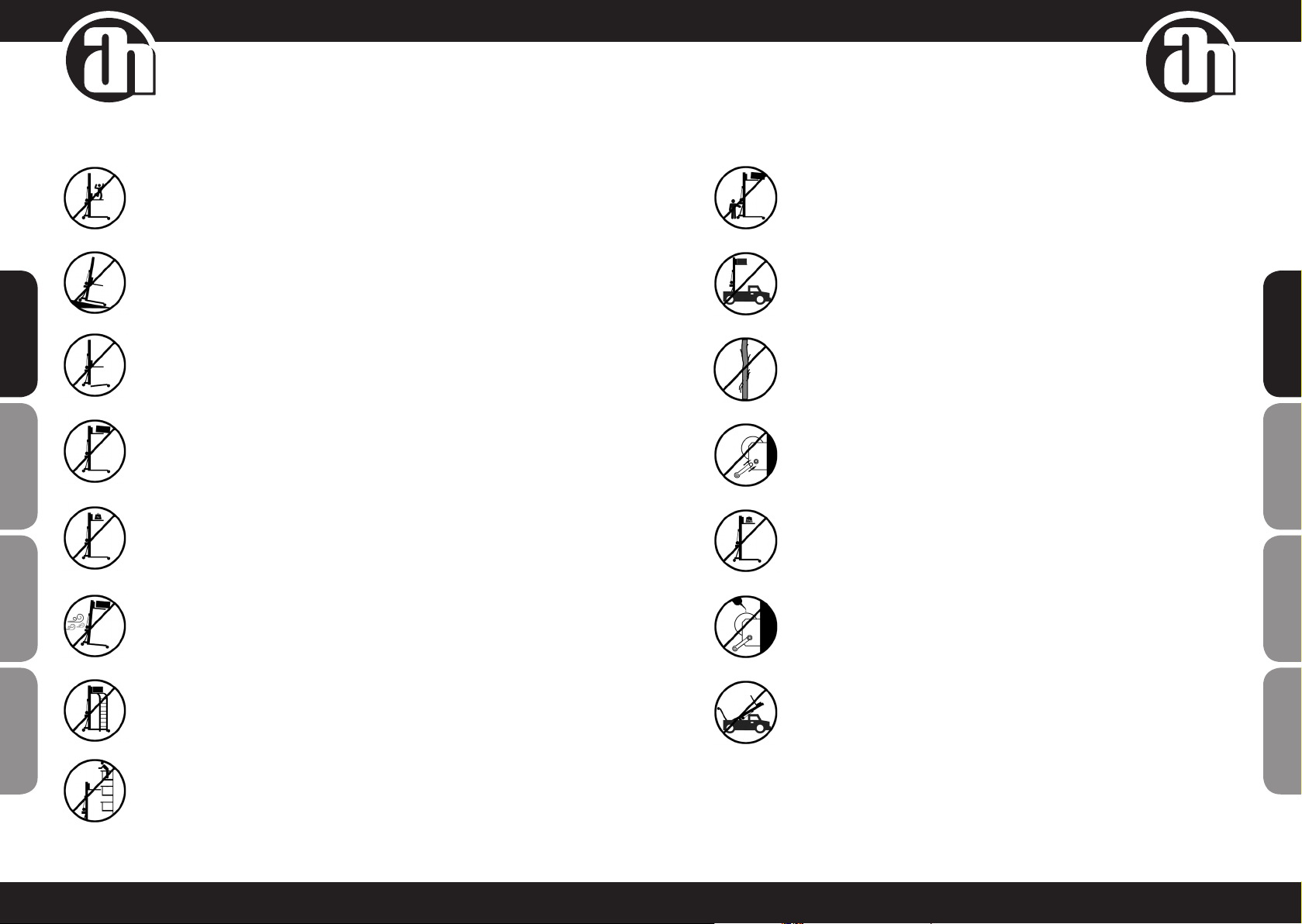
The lifting tower is an industrial element designed to raise loads vertically, it must NEVER be used
as a platform elevator for people.
Only place the lifting tower on rm at grounds checking it is in vertical position.
Do not use wedges or any strange elements to balance the hoist.
Check legs are correctly assembled and secured by their safety pins.
Never raise a load without rst checking it is correctly supported and centred on the appropriate
lifting tower supports, so the load only acts vertically.
Never surpass the maximum load capacity indicated on the lifting tower label of characteristics and
this instruction manual.
If there is a likelihood of strong wind or gusts, place the lifting tower on the ground and secure it
with the aid of straps. Never x a strap over a vehicle or any other element which might move.
Never use a ladder over the lifting tower or leaning against it for any kind of work.
Beware of any kind of projection above the lifting tower like cornices, balconies, luminous signs,
etc. It is very important to avoid the presence of cables below the lifting tower working height.
Never move the lifting tower when the load is raised. It is inadvisable to make any kind of
movement, even small positioning adjustments.
Never use the lifting tower over any mobile surface or vehicle.
Before using the lifting tower, check the cable state, which must not present any broken threads or
compression. NEVER EVER use defective cables and change cable if in doubt. Only use steel cable as
described in this manual.
Fix the lever when the load is raised.
Minimum load for braking function without problems is 25kg. Brake will not function without this minimum
load.
Neither grease nor lubricate the winch brake mechanism. Braking disks were greased with a special
heat and pressure resistant grease.
No other products must be used to prevent negative inuence on brake functioning.
All sections must be lowered to transport the lifting tower.
6 7
ENGLISH
ENGLISH
DEUTSCH
DEUTSCH
FRANCAISFRANCAIS
FRANCAISFRANCAIS FRANCAISFRANCAIS
FRANCAISFRANCAIS FRANCAISESpAñoL
FRANCAISESpAñoL
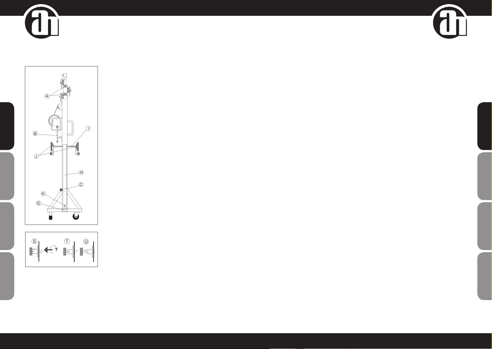
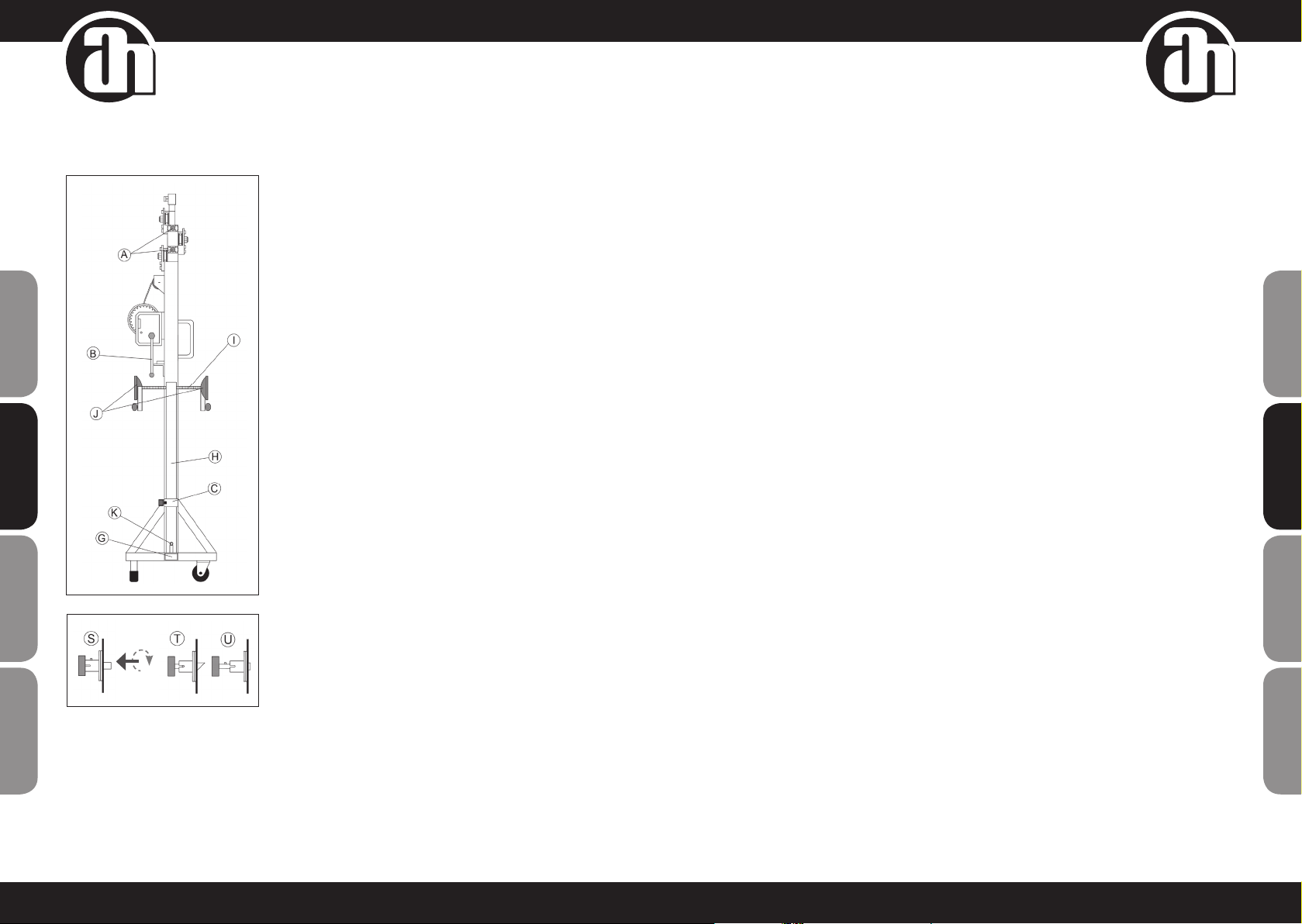
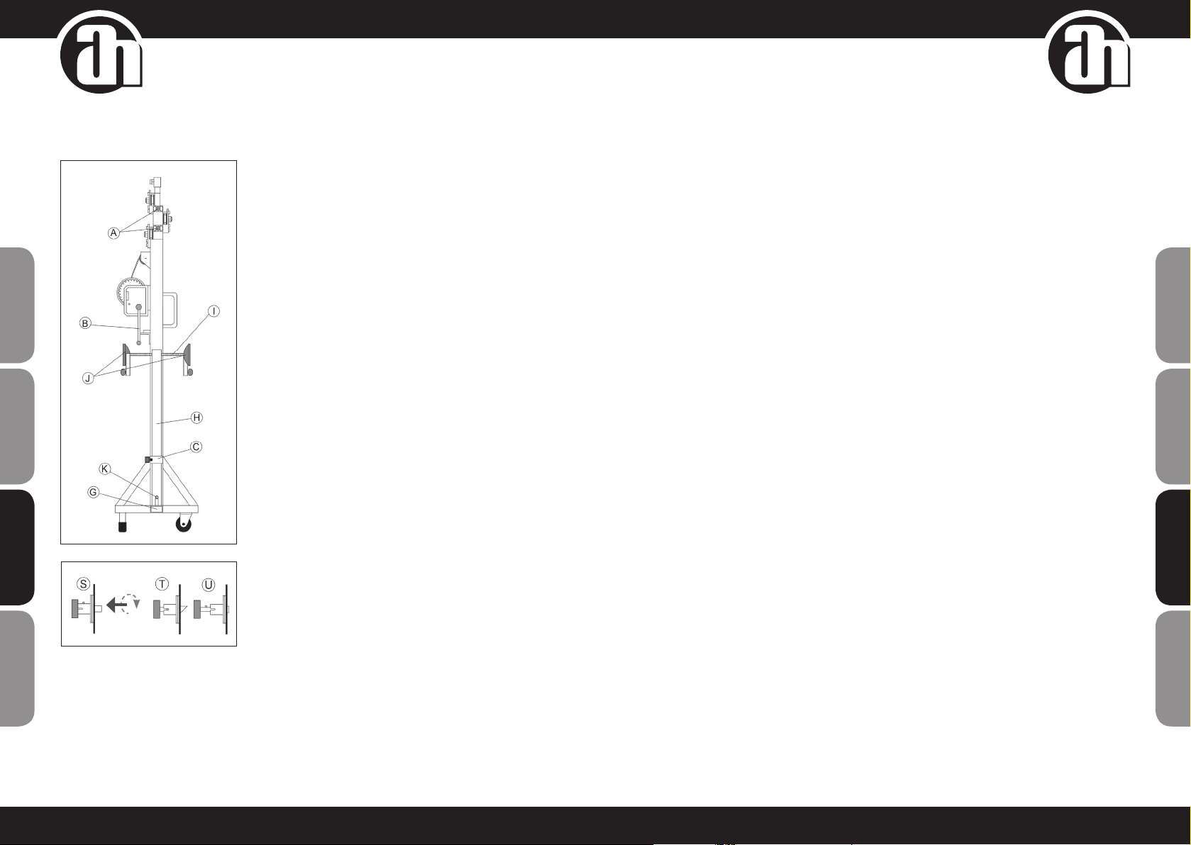
1. Place the lifting tower over a rm and at surface in its working
place.
2. Remove the outriggers (H) from their transport supports (C) and
insert them into their working positions (G) checking that they are
xed by the safety pins (K).
3. Adjust the outrigger stabilisers (J) by turning the cranks (I) to
level the lifting tower. Ensure it is in a vertical position checking
the bubble level.
4. Put the load on top of the lifting tower using the suitable support,
in order to make the weight of the load work only in vertical
direction. The minimum load must be 25 kg. It is possible to
manually block it with the safety pins (A).
5. Elevation: Turn the winch handle (B) clockwise to lift the load until
the desired position, checking that safety pins (A) are activated (T).
6. Lowering: release the safety pins (A) doing the action U. To
release them, turn slightly the winch handle to elevate the load.
In the normal working position, the load’s weight does not allow
to release the safety pins. Once the safety pin (A) is unblocked,
turn the winch handle (B) counter-clockwise until lowering the
load and the rst prole is completely down. Release the safety
pins (A) and keep on lowering the lifting tower until the second
prole is completely down. Unblock the safety pin (A) and
continue lowering the lifting tower until it is completely folded as
its minimum height. The lifting tower can be xed in any needed
intermediate position as well as when raising the load, xing the
safety pin (A) in the position (S).
7. For the lifting towers’ transport it necessary to bring down all the
proles, releasing the safety pin (A) doing the action U. To x the
proles with the safety pins (A) in the position (S).
4. HOW TO USE 5. MAINTENANCE
1. Periodically check cable status. If the cable seems to have broken cable wires or crushing, replace
immediately with a new one. Never use the lifting tower with cables in bad conditions. Only use galvanized
steel cable under EN12385-4. Right hand ordinary lay.
MaxLoad: 9375N. Tensile strength: 1770N /mm². Diameter: 4 mm. Length: 9 m.
2. The lifting tower is supplied fully greased from factory. Nevertheless, periodical greasing is recommended
as per use to the crown gear of the winch, to the threaded bar of the stabiliser outriggers and the proles.
WARNING: DO NOT GREASE OR LUBRICATE BRAKING MECHANISM
Braking disks were greased with a special heat and pressure resistant grease. No other product must used
to prevent negative inuence on brake function.
3. Lifting tower Stagelift 150, must be checked by an expert once a year minimum as per its use.
4. Only original spare parts must be used to ensure continued safe use. The user loses all guarantee rights if
spare parts other than the originals are incorporated or modify the product in any way.
5. To request any spare part, contact the manufacturer or an authorised distributor within your territory.
6. SPECIFIC RISKS
BRAKING SYSTEM FAILURE
May occur due to braking system deciencies or bad installation If it stops working it could cause a serious risk
because the raised load will be out of control and injure users or hit materials next to the tower.
LOSS OF STABILITY
If the tower is placed on a sloping ground or a surface that is not completely at there is a risk of loss stability
which would lead to a 90 º overturn with risk of serious injuries for workers and material.
OBJECTS DROPPING TO A DIFFERENT LEVEL
As an elevation equipment and because of the working height, there is a serious risk of raised objects dropping
to a different level, either due to securing mechanism failure, part wear, dirt, etc., or incorrect use of the lifting
tower (E.g.: for goods over the maximum load allowed). Sudden drop of raised goods implies a serious risk for
worker and material
KNOCKS AND /OR CONTUSIONS DUE TO OBJECTS
This risk only occasionally causes an accident to the worker running the operation due to his location during
the elevation process; nthe risk of knocks from a raised element is more likely to affect people walking by or
whose workplace is next to the lifting tower. Its origin may be due to loss of stability, malfunctioning of structural
elements, safety systems, securing systems, etc.
8 9
ENGLISH
ENGLISH
DEUTSCH
DEUTSCH
FRANCAISFRANCAIS
FRANCAISFRANCAIS FRANCAISFRANCAIS
FRANCAISFRANCAIS FRANCAISESPAÑOL
FRANCAISESPAÑOL

7. PREVENTION SYSTEMS
BRAKING SYSTEM FAILURE
Equip with winch complying with regulations metioned in the BGV C1 directive, specially DIN 56925 and DIN EN 292.
LOSS OF STABILITY
Maintenance of lifting tower stability must basically be as per the following measures:
• Professional, training and risk awareness of lifting tower users.
• Equip with different safety devices and advices from the manufacturer to reinforce stability, like:
• Safety pins which secure the lifting tower once raised.
• Bubble level to help vertical adjustment.
• Fixing maximum load that the lifting tower can raise.
• Maximum slope specication which the lifting tower can access safely.
OBJECTS FALLING TO A DIFFERENT LEVEL, KNOCKS AND /OR CONTUSIONS FROM OBJECTS
The risk of objects falling to a different level can be prevented using homologated safety elements, e.g., a safety
pin which xes the interior prole of the lifting tower in its working position, so the cable does not support load
and guaranteeing impossibility of a drop. In the event of cable breakage, the braking system will act automatical-
ly. Furthermore, if steel elements have been zinc coated this protects the entire unit from oxidation and corrosion.
These risks can also be minimised with correct lifting tower maintenance. The user must perform periodical
inspections on safety elements and make the necessary repairs in case of detecting deciencies Moreover,
the consequences of these risks can be reduced limiting an access area to the lifting tower and with a correct
training of personnel.
NOISE EMISSIONS
This equipment does not produce more than 80 decibels.
10 11
ENGLISH
ENGLISH
DEUTSCH
DEUTSCH
FRANCAISFRANCAIS
FRANCAISFRANCAIS FRANCAISFRANCAIS
FRANCAISFRANCAIS FRANCAISESpAñoL
FRANCAISESpAñoL
WARRANTY PROVISIONS
This warranty applies to the product you purchased from Adam Hall
The statutory warranty rights against the vendor are not affected by this warranty. Rather, this warranty gives you
additional independent claims against Adam Hall.
With this warranty, Adam Hall ensures that products you have purchased from Adam Hall or Adam Hall partners,
under normal use, are free of defects in material or workmanship for a period of 2 years from the date of
purchase. The warranty period begins on the date of purchase. In order to assert a claim for warranty service, the
proof of date of purchase is provided by the receipt bearing the date of purchase or the date of purchase on the
delivery note. You are entitled to warranty service under the conditions and provisions set out in this document, if
a repair within the warranty period is required.
This warranty applies only to the original purchaser of the products supplied by Adam Hall and is not transferable
to any person to whom the property is transferred by the original purchaser.
Within the warranty period, the defective parts or the product from Adam Hall will be repaired or replaced. Under
the terms of this warranty, all the replaced or removed components become the property
of Adam Hall.
In the unlikely event that a product acquired from Adam Hall, repeatedly exhibits a defect, Adam Hall may decide,
at its discretion, to replace this product with a comparable product of at least the same performance.
Adam Hall does not guarantee that the operation of this product will be uninterrupted or error-free. Adam Hall ac-
cepts no responsibility for any damage due to incorrect compliance with the instructions received in the delivery.
This warranty does not extend to:
• wearing parts (eg battery, tubes)
• devices that have had their serial number removed or damaged, or failed as a result of an accident
• inappropriate or abusive use or other external causes
• devices that were not used in accordance with the operating parameters defined in the user documentation
shipped with the product
• devices that have been repaired using parts not made or distributed by Adam Hall
• devices that have been serviced, modified or repaired by someone other than Adam Hall or an authorised
service partner.
These terms and conditions constitute the complete and exclusive warranty agreement between you and Adam
Hall regarding the Adam Hall branded product you have purchased.
This warranty is valid only within Europe. Outside of Europe please contact our official distributors.

12 13
ENGLISH
ENGLISH
DEUTSCH
DEUTSCH
FRANCAISFRANCAIS
FRANCAISFRANCAIS FRANCAISFRANCAIS
FRANCAISFRANCAIS FRANCAISESpAñoL
FRANCAISESpAñoL
LIMITATION OF LIABILITY
If your Adam Hall branded hardware product fails to work as warranted above, your sole and exclusive remedy
shall be repair or replacement. Adam Halls’ maximum liability under this limited warranty is expressly limited to
the lesser of the price you have paid for the product or the cost of repair or replacement of any components that
malfunction under conditions of normal use. Adam Hall is not liable for any damages caused by the product or
the failure of the product, including any lost prots or savings or special, incidental, or consequential damages.
Adam Hall is not liable for any claim made by a third party or made by you for a third party.
This limitation of liability applies whether damages are sought, or claims are made, under this Limited Warranty
or as a tort claim (including negligence and strict product liability), a contract claim, or any other claim, and
cannot be rescinded or changed by anyone. This limitation of liability will be effective even if you have advised
Adam Hall or an authorized representative of Adam Hall of the possibility of any such damages, but not, however,
in the event of claims for damages in connection with personal injuries. This manufacturer’s warranty grants you
specic rights; depending on jurisdiction (nation or state), you may be be entitled to additional claims. You are
advised to consult applicable state or national laws for a full determination of your rights.
REQUESTING WARRANTY SERVICE
To request warranty service for the product, contact Adam Hall or the Adam Hall authorized reseller from which
you purchased the product.
ENVIRONMENTAL PROTECTION AND ENERGY CONSERVATION
Energy conservation is an active contribution to environmental protection. Please turn off all unneeded elec
trical
devices. To prevent unneeded devices from consuming power in standby mode, disconnect the mains plug.
Adam Hall GmbH, all rights reserved. The technical data and the functional product characteristics can be subject to modifications. The photocopying,
the translation, and all other forms of copying of fragments or of the integrality of this user’s manual is prohibited.
14 15
ENGLISH
ENGLISH
DEUTSCH
DEUTSCH
FRANCAISFRANCAIS
FRANCAISFRANCAIS FRANCAISFRANCAIS
FRANCAISFRANCAIS FRANCAISESPAÑOL
FRANCAISESPAÑOL
STAGELIFT150
KURBELLIFT

1. EINFÜHRUNG
Diese Anleitung wurde nach den Vorgaben der europäischen Maschinenrichtlinie 2006/42/EG erstellt.
Sie sollte daher vor, während und nach dem Gebrauch des Kurbellifts sowie bei Bedarf zu Rate gezogen werden,
wobei alle Inhalte zu allen zugehörigen Bauteilen zu berücksichtigen sind. Nur auf diese Weise kann die Ge-
brauchsanweisung ihre wichtigsten Ziele, nämlich die Vermeidung von Unfallrisiken und den optimalen Betrieb
des Kurbellift, erfüllen. In dieser Anleitung wird besonderer Wert auf Sicherheitsaspekte und die Vermeidung von
Arbeitsunfällen im Umgang mit diesem Produkt gelegt. Daher sind die für den Anwender besonders wichtigen
Passagen hervorgehoben.
VORSICHT: LESEN SIE DIESES HANDBUCH GRÜNDLICH DURCH, BEVOR SIE DEN TRAVERSENLIFT
VERWENDEN
2. ALLGEMEINE INFORMATIONEN
2.1. TECHNISCHE DATEN
NAME Kurbellift
MODELL Stagelift 150
TECHNISCHE DATEN
Maximale Höhe: 5,30 m
Minimale Höhe: 1,73 m
Maximale Hublast: 150 kg
Mindestlast: 25 kg
Material: Stahl nach DIN 2394
Stelläche geöffnet: 1,90 x 1,90 m
Stelläche geschlossen: 0,38 x 0,38 m
Gewicht: 48 kg
Winde: 450 kg maximale Hublast mit automatischer Lasthaltebremse
Seil: Verzinktes Stahlseil nach EN12385-4, Kreuzschlag rechtsgängig
Maximale Zugkraft: 9375 N
Zugfestigkeit: 1770 N/mm², Durchmesser: 4 mm, Länge: 9 m
Fixierung der Turmsegmente auf Arbeitshöhe mit Sicherungssplinten.
Auslegerverankerung mit Sicherheitssplinten.
Schützende Lackierung gegen Rost und Oberächenschäden.
BESCHREIBUNG Der Kurbellift Stagelift 150 dient zum Anheben von Montage-,
Beleuchtungs- und Beschallungselementen auf unterschiedliche
Höhen. Das Gerät wurde von geschultem Personal geprüft und hat
sämtliche Betriebs-, Last- und Maßprüfungen bestanden.
HERSTELLER Adam Hall GmbH
ADRESSE Daimlerstraße 9 ∙ 61267 Neu-Anspach ∙ Deutschland
ABBILDUNGEN
2.2. ANWENDBARE BESTIMMUNGEN
• EUROPÄISCHE MASCHINENRICHTLINIE 2006/42/EG
• BGV C1 (GUV 6.175)
• BGG 912 (GUV 66.15, GUV G-912)
• EN 12385-4:2008-06
• DIN EN 10305-3:2010-05
16 17
ENGLISH
ENGLISH
DEUTSCH
DEUTSCH
FRANCAISFRANCAIS
FRANCAISFRANCAIS FRANCAISFRANCAIS
FRANCAISFRANCAIS FRANCAISESPAÑOL
FRANCAISESPAÑOL

18 19
ENGLISH
ENGLISH
DEUTSCH
DEUTSCH
FRANCAISFRANCAIS
FRANCAISFRANCAIS FRANCAISFRANCAIS
FRANCAISFRANCAIS FRANCAISESpAñoL
FRANCAISESpAñoL
3. ALLGEMEINE SICHERHEITSVORKEHRUNGEN
Der Kurbellift ist eine industrielle Einrichtung zum vertikalen Anheben von Lasten und darf NIEMALS
zum Transport von Personen verwendet werden.
Der Kurbellift muss senkrecht auf einem festen und ebenen Untergrund aufgestellt werden.
Verwenden Sie keine Keile oder anderen Objekte, um den Kurbellift auszurichten.
Stellen Sie sicher, dass die Ausleger korrekt montiert und mit den zugehörigen Sicherungssplinten
gesichert sind.
Stellen Sie vor dem Anheben einer Last sicher, dass die Last richtig ausgerichtet auf den Hebear-
men liegt, damit die Last nur senkrecht wirkt.
Überschreiten Sie niemals die auf dem Typenschild und in der Bedienungsanleitung angegebene
Maximallast.
Bei Gefahr von starkem Wind oder Böen sichern Sie den Kurbellift mit Gurten am Boden. Befestigen
Sie die Gurte niemals an Fahrzeugen oder anderen beweglichen Gegenständen.
Arbeiten Sie im Bereich des Kurbellifts niemals mit Leitern und lehnen Sie auch keine Leitern an
den Kurbellift.
Achten Sie im Bereich oberhalb des Kurbellifts auf überhängende Elemente wie Brüstungen,
Balkone, Leuchtschilder etc. Vermeiden Sie den Betrieb unter Leitungen, die tiefer hängen als die
maximale Arbeitshöhe des Kurbellifts.
Bewegen Sie den Kurbellift niemals in beladenem Zustand. Vermeiden Sie auch kleinere Bewegun-
gen wie z.B. Positionskorrekturen.
Verwenden Sie den Kurbellift niemals auf beweglichem Untergrund oder auf Fahrzeugen.
Überprüfen Sie den Zustand des Zugseils vor dem Betrieb des Kurbellifts auf gebrochene Litzen
und Verformungen. Verwenden Sie NIEMALS defekte Seile und ersetzen Sie das Seil im Zweifels-
fall. Verwenden Sie nur die in diesem Handbuch genannten Stahlseile.
Sichern Sie nach Anheben der Last die Kurbel.
Die Mindestlast für eine ordnungsgemäße Funktion des Bremsmechanismus beträgt 25kg. Ohne
diese Mindestlast funktioniert die Bremse nicht.
Schmieren und ölen Sie den Bremsmechanismus der Winde nicht. Die Bremsscheiben sind mit
einem speziellen Hitze- und Druck-resistenten Schmiermittel geschmiert. Um eine Beeinträchti-
gung der Bremsfunktion zu vermeiden, dürfen keine anderen Schmiermittel verwendet werden.
Für den Transport müssen alle Segmente eingefahren werden.
4. ANWENDUNG
1. Stellen Sie den Kurbellift am Arbeitsort auf einem festen und
ebenen Untergrund auf.
2. Nehmen Sie die Stützausleger (H) aus den Transporthalterungen
(C) und führen Sie diese in die Arbeitsaufnahmen (G) ein. Achten
Sie darauf, dass sie von den Sicherungssplinten (K) arretiert
werden.
3. Um den Kurbellift auszurichten, passen Sie die Höhe der Stabilisa-
toren an den Auslegern (J) mit den Kurbeln (I) an. Stellen Sie mit
einer Wasserwaage sicher, dass der Kurbellift absolut waagrecht
steht.
4. Beladen Sie den Kurbellift unter Verwendung der passenden
Aufnahme so, dass das Gewicht ausschließlich senkrecht auf den
Turm wirkt. Das Gewicht muss mindestens 25kg betragen. Mit
Hilfe des Sicherungssplints (A) kann die Last manuell gesichert
werden.
5. Anheben: Drehen Sie die Kurbel (B) im Uhrzeigersinn, um die Last
auf die gewünschte Höhe anzuheben, und stellen Sie sicher, dass
der Sicherungssplint (A) einrasten (T).
6. Absenken: Lösen Sie den Sicherungssplint (A) indem Sie Schritt
(U) durchführen. Zum Lösen der Sicherungssplinte heben Sie die
Last durch Drehen der Kurbel zunächst etwas an. In der normalen
Arbeitsposition verhindert das Gewicht der Last, dass sich die
Sicherungssplinte lösen. Sobald der Sicherungssplint (A) gelöst ist,
drehen Sie die Kurbel (B) gegen den Uhrzeigersinn, um die Last
abzusenken, bis das erste Prol vollständig eingefahren ist. Lösen
Sie den Sicherungssplint (A) und senken Sie den Kurbellift weiter
ab, bis das zweite Prol vollständig eingefahren ist. Entriegeln Sie
den Sicherungssplint (A) und senken Sie den Kurbellift weiter ab,
bis er auf seine Minimalhöhe eingefahren ist. Der Kurbellift lässt
sich während des Anhebens und Absenkens in jeder beliebigen
Höhe xieren, indem der Sicherungssplint (A) in Position (S)
arretiert wird.
7. Zum Transport müssen sämtliche Prole durch Lösen des
jeweiligen Sicherungssplints (A) indem Sie Schritt (U) durchführen
vollständig eingefahren werden. Fixieren Sie die Prole mit dem
Sicherungssplint (A) in Position (S).
5. WARTUNG
1. Überprüfen Sie in regelmäßigen Abständen den Zustand des Seils. Falls das Kabel beschädigt oder gequetscht
zu sein scheint, ersetzen Sie es umgehend durch ein neues. Verwenden Sie den Kurbellift keinesfalls, wenn
das Seil nicht in Ordnung ist. Verwenden Sie ausschließlich Kabel nach DIN EN12385-4, Kreuzschlag rechts-
gängig.
Maximale Zugkraft: 9375 N Zugfestigkeit: 1770 N/mm² Durchmesser: 4 mm Länge: 9 m
2. Der Kurbellift wird bereits vollständig geschmiert ausgeliefert. Dennoch wird empfohlen, das Zahnrad der
Winde, die Gewindestangen der Stabilisatoren und die Prole regelmäßig bei jedem Gebrauch zu schmieren.
WARNUNG: DEN BREMSMECHANISMUS NICHT SCHMIEREN ODER ÖLEN
Die Bremsscheiben sind mit einem speziellen Hitze- und Druck-resistenten Schmiermittel geschmiert. Um
eine Beeinträchtigung der Bremsfunktion zu vermeiden, dürfen keine anderen Schmiermittel verwendet
werden.
3. Der Kurbellift Stagelift 150 muss je nach Einsatzhäugkeit mindestens einmal jährlich von einem Fachmann
überprüft werden.
4. Um einen dauerhaft sicheren Betrieb zu gewährleisten, dürfen ausschließlich Originalersatzteile verwendet
werden. Bei Verwendung nicht originaler Ersatzteile oder jeglicher Modikation des Produkts verliert der
Anwender sämtliche Garantieansprüche.
5. Um Ersatzeile anzufordern, wenden Sie sich an den Hersteller oder einen autorisierten Händler in Ihrer
Region.
6. SPEZIFISCHE RISIKEN
VERSAGEN DES BREMSSYSTEMS
Ursache können ein fehlerhaftes Bremssystem oder ein Installationsfehler sein. Ein Versagen des Bremssystems
kann ein ernstes Risiko darstellen, da die nun ungesicherte, angehobene Last den Anwender verletzen oder Gegen-
stände im Bereich des Kurbellifts beschädigen kann.
STABILITÄTSVERLUST
Wenn der Kurbellift auf einem schrägen oder unebenen Untergrund aufgestellt wird, besteht die Gefahr eines Sta-
bilitätsverlusts, was zu einem Umstürzen des Kurbellifts und in der Folge zu ernsthaften Verletzungen von Arbeitern
sowie zu Sachschäden führen kann.
FALLENDE GEGENSTÄNDE
Bei Hebevorrichtungen besteht aufgrund der Arbeitshöhe ein großes Risiko, dass Gegenstände auf tieferliegende
Ebenen herunterfallen. Ursache können ein Versagen der Sicherheitseinrichtungen, Verschleiß, Verschmutzung
20 21
ENGLISH
ENGLISH
DEUTSCH
DEUTSCH
FRANCAISFRANCAIS
FRANCAISFRANCAIS FRANCAISFRANCAIS
FRANCAISFRANCAIS FRANCAISESPAÑOL
FRANCAISESPAÑOL

oder Bedienfehler am Kurbellift (z.B. ein Überschreiten der zulässigen Höchstlast) sein. Ein plötzliches Herunterfallen
angehobener Gegenstände stellt ein großes Risiko für Arbeiter und Material dar.
SCHLÄGE UND / ODER STÖSSE DURCH HERABFALLENDE ELEMENTE
Das Risiko, von einem herabfallenden Element des Kurbellifts getroffen zu werden, betrifft nur in seltenen Fällen den
Bediener des Kurbellifts selbst, sonder eher Personen, die am Kurbellift vorbeilaufen oder in seiner Nähe arbeiten. Die
Ursache kann ein Stabilitätsverlust, Materialversagen oder ein Ausfall der Sicherungssysteme etc. sein.
7. SICHERUNGSSYSTEME
VERSAGEN DES BREMSSYSTEMS
Die Winde entspricht den Vorgaben der Richtlinie BGV C1, insbesondere DIN 56925 und DIN EN 292.
STABILITÄTSVERLUST
Die Stabilität des Kurbellifts muss durch folgende Maßnahmen sichergestellt werden:
• Professionelle Unterweisung und Risikobewusstsein der Benutzer des Kurbellifts.
• Erhöhung der Stabilität durch Sicherungseinrichtungen und -anweisungen des Herstellers wie z.B.:
• Sicherungssplinte zum Sichern des Kurbellifts in ausgefahrenem Zustand
• Libelle zur Vereinfachung der waagrechten Aufstellung
• Begrenzung der Maximallast
• Spezikation der maximalen Neigung des Kurbellifts.
HERUNTERFALLENDE GEGENSTÄNDE, SCHLÄGE UND / ODER STÖSSE DURCH HERABFALLENDE ELEMENTE
Um das Risiko durch herabfallende Gegenstände zu minimieren, können geprüfte Sicherheitseinrichtungen eingesetzt
werden, beispielsweise Sicherungssplinte, die den Kurbellift in Arbeitsposition sichern, sodass das Seil nicht unter Last
steht und ein Herabfallen ausgeschlossen ist. Sollte das Seil reißen, greift automatisch das Bremssystem. Alle Stahl-
bauteile sind verzinkt, sodass das gesamte System vor Rost geschützt ist. Auch durch eine korrekte Wartung können
die Risiken minimiert werden. Der Benutzer muss die Sicherheitsvorrichtungen in regelmäßigen Abständen überprüfen
und gegebenenfalls reparieren. Außerdem lassen sich die möglichen Konsequenzen der Risiken begrenzen, indem der
Zugang zum Bereich des Traversenlifts gesichert und das Personal entsprechend
geschult wird.
GERÄUSCHEMISSIONEN
Die Geräuschemissionen dieses Produkts liegen unterhalb von 80 Dezibel.
22 23
ENGLISH
ENGLISH
DEUTSCH
DEUTSCH
FRANCAISFRANCAIS
FRANCAISFRANCAIS FRANCAISFRANCAIS
FRANCAISFRANCAIS FRANCAISESpAñoL
FRANCAISESpAñoL
HERSTELLERGARANTIE
Diese Garantie erstreckt sich auf das von Ihnen erworbene Adam Hall Produkt
Die gesetzlichen Gewährleistungsrechte gegenüber dem Verkäufer werden von dieser Garantie nicht berührt. Vielmehr
begründet diese Garantie zusätzliche selbständige Ansprüche gegenüber Adam Hall.
Mit dieser Garantie stellt Adam Hall sicher, dass das von Ihnen bei Adam Hall oder einem Adam Hall Partner erworbene
Produkt, bei normalem Gebrauch während des Zeitraums von 2 Jahren ab Kaufdatum frei von Material- oder Verarbei-
tungsfehlern ist. Der Garantiezeitraum beginnt mit dem Datum des Kaufs. Der Geltendmachung eines Anspruchs auf
Garantieleistungen erforderliche Nachweis des Kaufdatums, erfolgt durch die mit dem Kaufdatum versehene Quittung
oder den mit dem Kaufdatum versehenen Lieferschein. Sie haben Anspruch auf den Garantieservice zu den in diesem
Dokument aufgeführten Bedingungen und Bestimmungen, falls eine Reparatur innerhalb des Garantiezeitraums
erforderlich ist.
Diese Garantie gilt nur für den ursprünglichen Käufer des von Adam Hall vertriebenen Produkts und ist nicht an Per-
sonen übertragbar, denen vom ursprünglichen Käufer das Eigentum am Adam Hall Produkt übertragen wird.
Innerhalb des Garantiezeitraums werden die fehlerhaften Komponenten oder das Produkt von Adam Hall repariert oder
ersetzt. Alle im Rahmen dieser Garantie ausgetauschten bzw. entfernten Komponenten gehen in das Eigentum
von Adam Hall über.
In dem unwahrscheinlichen Fall, dass bei dem von Ihnen erworbenen Adam Hall Produkt ein Fehler wiederholt auftritt,
kann Adam Hall nach eigenem Ermessen entscheiden, Ihnen dieses Produkt durch ein vergleichbares Produkt mit
mindestens derselben Leistung zu ersetzen.
Adam Hall übernimmt keine Garantie für einen störungs- oder fehlerfreien Betrieb dieses Produkts. Adam Hall über-
nimmt keine Verantwortung für Schäden die auf eine inkorrekte Befolgung der im Lieferumfang erhaltenen Anweisun-
gen zurückzuführen sind.
Diese Garantie erstreckt sich nicht auf:
• Verschleißteile (z.B. Akkumulator, Röhren).
• Geräte deren Seriennummer entfernt wurde oder die beschädigt oder fehlerhaft wurden als Folge eines Unfalls
• nicht sachgerechter oder missbräuchlicher Verwendung oder anderer äußerer Ursachen
• Geräte die nicht entsprechend den Betriebsparametern betrieben wurden, die in den im Lieferumfang des Produkts
enthaltenen Benutzerunterlagen festgelegt sind
• Geräte die aufgrund der Verwendung nicht von Adam Hall hergestellter oder vertriebener Teile repariert wurden
• Geräte die durch jemand anderen als Adam Hall oder durch einen autorisierten Servicepartner gewartet, geändert
oder repariert wurden.
Diese Bestimmungen und Bedingungen stellen die vollständige und ausschließliche Garantievereinbarung zwischen
Ihnen und Adam Hall für das von Ihnen erworbene Adam Hall Produkt dar.
Diese Garantie ist nur innerhalb von Europa gültig. Außerhalb von Europa wenden Sie sich bitte an unsere offiziellen
Vertriebspartner.

24 25
ENGLISH
ENGLISH
DEUTSCH
DEUTSCH
FRANCAISFRANCAIS
FRANCAISFRANCAIS FRANCAISFRANCAIS
FRANCAISFRANCAIS FRANCAISESpAñoL
FRANCAISESpAñoL
HAFTUNGSBESCHRÄNKUNG
Falls an Hardware-Produkten von Adam Hall innerhalb der Garantiezeit Material- oder Verarbeitungsfehler (gemäß
der Garantieerklärung oben) auftreten, besteht Ihr alleiniger und ausschließlicher Anspruch aus dieser Garantie in
der Reparatur oder dem Austausch des Geräts. Die maximale Haftung der Firma Adam Hall ist entsprechend dieser
Garantie ausdrücklich auf den Kaufpreis oder die Kosten für eine Reparatur oder Ersatz – und zwar den jeweils
niedrigeren Betrag – der bei üblichem Gebrauch fehlerhaften Komponenten begrenzt.
Adam Hall ist nicht haftbar für jegliche durch das Produkt oder das Versagen des Produkts verursachte Schäden,
einschließlich Gewinneinbußen und unterbliebener Einsparungen sowie besonderer, indirekter oder Folgeschäden.
Des Weiteren ist Adam Hall nicht haftbar gegenüber Rechtsansprüchen Dritter oder durch Sie im Namen Dritter
angemeldeten Forderungen.
Diese Haftungsbeschränkung gilt unabhängig davon, ob Schäden gerichtlich verfolgt oder Schadensersatz-
ansprüche im Rahmen dieser Garantie oder aufgrund unerlaubter Handlungen (einschließlich Fahrlässigkeit und
Gefährdungshaftung) oder aufgrund vertraglicher oder sonstiger Ansprüche gestellt werden, und kann von
niemandem aufgehoben oder verändert werden. Diese Haftungsbeschränkung ist auch dann gültig, wenn Sie die
Firma Adam Hall oder einen autorisierten Vertreter von Adam Hall auf die Möglichkeit solcher Schäden aufmerksam
gemacht haben, nicht jedoch bei Schadensersatzansprüchen in Zusammenhang mit Personenschäden.
Diese Herstellergarantie räumt Ihnen bestimmte Rechte ein; je nach Gerichtsbarkeit (Staat oder Land) stehen Ihnen
möglicherweise weitere Ansprüche zu. Es ist ratsam, in solchen Fällen die entsprechenden Gesetze heranzuziehen,
um Ihre Rechte umfassend zu ermitteln.
INANSPRUCHNAHME DER GARANTIE
Wenden Sie sich im Garantiefall direkt an Adam Hall oder den von Adam Hall autorisierten Händler, bei dem Sie das
Produkt erworben haben.
UMWELTSCHUTZ UND ENERGIESPAREN
Energiesparen ist ein aktiver Beitrag zum Umweltschutz. Schalten Sie bitte alle nicht benötigten elektrischen
Geräte aus. Um zu verhindern, dass nicht benötigte Geräte im Standby-Modus Strom verbrauchen, ziehen Sie den
Netzstecker.
Adam Hall GmbH, alle Rechte vorbehalten. Die technischen Daten und die funktionalen Produkteigenschaften können Änderungen und Irrtümer
vorbehalten. Das Kopieren, die Übersetzung, und alle anderen Formen des Kopierens von Fragmenten oder der Vollständigkeit dieser Bedienungs-
anleitung ist untersagt.
26 27
ENGLISH
ENGLISH
DEUTSCH
DEUTSCH
FRANCAISFRANCAIS
FRANCAISFRANCAIS FRANCAISFRANCAIS
FRANCAISFRANCAIS FRANCAISESPAÑOL
FRANCAISESPAÑOL
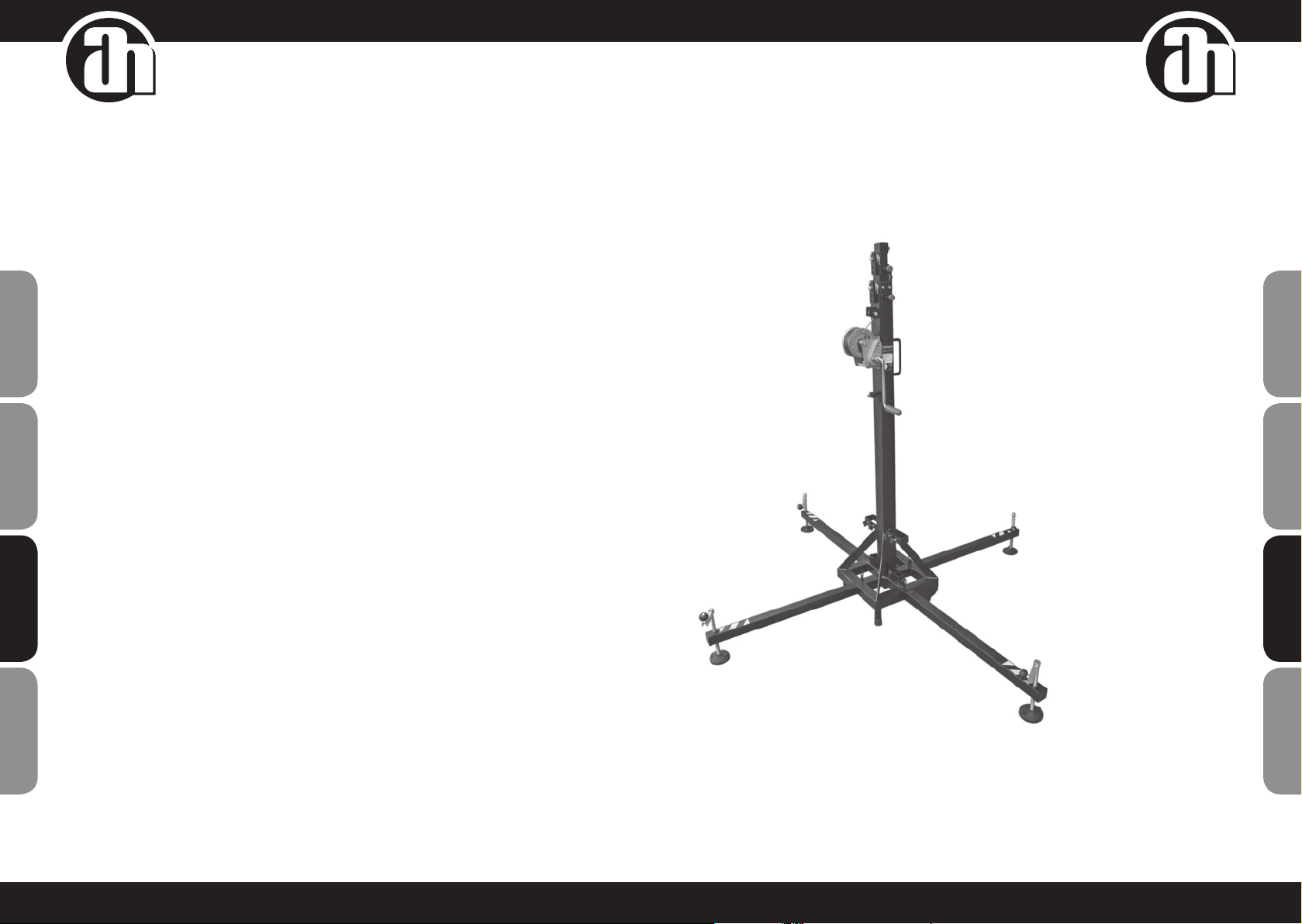
STAGELIFT150
PIED DE LEVAGE
1. INTRODUCTION
Ce manuel d'instructions a été élaboré conformément aux exigences de la Directive Machines CE 2006/42/EG
Ce manuel d'instructions constitue une partie intégrante de l'appareil de levage ; il doit être consulté avant, pen-
dant et après mise en place/utilisation de l'appareil, et dès que jugé nécessaire, en se conformant à son contenu.
Il s'agit là du seul moyen d'atteindre les objectifs de base établis dans le manuel, comme la prévention des
risques d'accident et l'optimisation maximale possible des fonctions de levage. Ce manuel expose dans le détail
les procédures de sécurité et de prévention d'accidents du travail,et fait ressortir les informations présentant un
intérêt particulier pour l'utilisateur.
ATTENTION: AVANT D'UTILISER L'APPAREIL DE LEVAGE, LISEZ CE MANUEL AVEC SOIN.
2. DONNÉES GÉNÉRALES
2.1. CARACTÉRISTIQUES TECHNIQUES
NOM pied de levage
RÉFÉRENCE MODÈLE Stagelift 150
CARACTÉRISTIQUES TECHNIQUES Hauteur maximale : 5,30 m
Hauteur minimale : 1,73 m
Charge maximale : 150 kg
Charge minimale : 25 kg
Matériau: Acier, conforme norme DIN 2394
Surface occupée par la base (pied ouvert) : 1,90 x 1,90 m
Surface occupée par la base (pied fermé) : 0,38 x 0,38 m
Masse : 48 kg
Treuil : Charge maximale 450 kg, frein automatique de rétention de
charge
Câble : Acier galvanisé, conforme EN12385-4. Brins croisés à droite
Charge maximale : 9375 N
Résistance à la traction : 1770 N/mm², diamètre : 4 mm, longueur
:
9 m
Fixation des sections du pied à hauteur de travail par goupilles de
sécurité.
Ancrage des jambes du pied par goupilles de sécurité.
Protection anti-corrosion et nition de protection peinte
DESCRIPTION DE L'APPAREIL Le pied de levage Stagelift 150 a été conçu pour le levage vertical
d'éléments de structures métalliques, d'appareils d'éclairage et de
sonorisation, à différentes hauteurs.
Il a été testé par un personnel qualié, et est conforme à tous les
critères de fonctionnement, de charge maximale et de dimensions.
SOCIÉTÉ Adam Hall GmbH
ADRESSE Daimlerstrasse 9 ∙ 61267 Neu-Anspach ∙ Allemagne
ILLUSTRATIONS
2.2. RÉGLEMENTATIONS APPLICABLES
• DIRECTIVES MACHINES CE 2006/42/EG
• BGV C1 (GUV 6.175)
• BGG 912 (GUV 66.15, GUE G-912)
• EN 12385-4:2008-06
• DIN EN 10305-3:2010-05
28 29
ENGLISH
ENGLISH
DEUTSCH
DEUTSCH
FRANCAISFRANCAIS
FRANCAISFRANCAIS FRANCAISFRANCAIS
FRANCAISFRANCAIS FRANCAISESPAÑOL
FRANCAISESPAÑOL

30 31
ENGLISH
ENGLISH
DEUTSCH
DEUTSCH
FRANCAISFRANCAIS
FRANCAISFRANCAIS FRANCAISFRANCAIS
FRANCAISFRANCAIS FRANCAISESpAñoL
FRANCAISESpAñoL
3. RÈGLES GÉNÉRALES DE SÉCURITÉ
Le pied de levage est un élément industriel, conçu pour le levage vertical de charges. Il ne doit
JAMAIS être utilisé pour comme ascenseur pour des personnes.
N'utilisez le pied de levage que sur une surface plane, et vériez sa perpendicularité.
N'utilisez pas de cale ou autre élément pour mettre à niveau le palan.
Vériez que les jambes sont assemblées correctement, et bien xées par leurs goupilles.
Ne levez jamais une charge sans avoir vérié au préalable qu'elle est correctement maintenue et
centrée sur les supports appropriés : elle doit s'élever à la verticale.
Ne dépassez jamais la capacité de charge maximale indiquée sur l'étiquette des caractéristiques
du pied de levage et dans ce manuel d'instructions.
En cas de probabilité de vents forts ou de rafales, haubannez le pied au sol avec des sangles.
Ne xez jamais une sangle sur un véhicule ou tout autre élément susceptible de bouger.
N'appuyez jamais une échelle sur le pied de levage, ne vous appuyez jamais dessus, quelle que
soit la tâche.
Attention à tout ce qui se trouve au-dessus du pied de levage : corniche, balcon, enseigne
lumineuse, etc. Il est très important d'éviter la présence de câbles en dessous de la hauteur de
travail du pied de levage.
Ne déplacez jamais le pied de levage lorsque la charge est levée. Il est déconseillé d'effectuer le
moindre déplacement, même de petits mouvements d'ajustement de position.
N'utilisez jamais le pied de levage au-dessus d'une surface mobile ou d'un véhicule.
Avant d'utiliser le pied de levage, vériez l'état du câble: il ne doit présenter aucun brin cassé ni
section comprimée. N'UTILISEZ JAMAIS de câbles défectueux : au moindre doute, remplacez le
câble. N'utilisez qu'un câble acier conforme aux caractéristiques données dans ce manuel.
Fixez le levier une fois la charge en l'air.
La charge minimale pour un fonctionnement sans problème du frein est de 25 kg. Le frein ne fonc-
tionnera pas correctement en dessous de cette charge minimale.
Ne graissez jamais, ne lubriez jamais le mécanisme de freinage du treuil. Les disques de freinage
ont été lubriés en usine avec une graisse spéciale, résistante à la chaleur et à la pression.
Aucun autre produit ne doit être utilisé, sous peine de mauvaises performances de freinage.
Pour le transport du pied de levage, toutes les sections doivent être baissées.
4. MODALITÉS D'UTILISATION
1. Placez le pied de levage sur une surface solide et plane pour
travailler.
2. Dégagez les bras-supports (H) de leurs logements de transport (C)
et insérez-les en position de travail (G), en vériant qu'ils sont xés
par les goupilles (K).
3. Réglez les stabilisateurs des bras-supports (J) en tournant les
manivelles (I) an de mettre la base du pied de levage à niveau
horizontal. Vériez la perpendicularité du pied sur le niveau à bulle.
4. Placez la charge en haut du pied de levage avec un support
adéquat, de façon à ce que le poids de la charge ne s'exerce que
dans la direction verticale. La charge minimale doit être de 25 kg.
Il est possible de la bloquer manuellement avec les goupilles (A).
5. Levage de la charge : Tournez la manivelle du treuil (B) dans le
sens des aiguilles d'une montre an de lever la charge jusqu'à la
hauteur désirée, en vériant que les goupilles de sécurité (A) sont
activées (T).
6. Pour abaisser la charge : dégagez les goupilles de sécurité (A)
en effectuant l‘étape (U). Pour les dégager, tournez légèrement la
manivelle du treuil pour lever la charge. Dans la position normale
de travail, le poids de la charge ne permet pas de dégager les
goupilles de sécurité. Une fois la goupille de sécurité débloquée,
tournez la poignée du treuil (B) dans le sens inverse des aiguilles
d'une montre jusqu'à ce que la charge s'abaisse et que le premier
prolé arrive complètement en bas. Débloquez les goupilles de
sécurité (A) puis continuez à baisser le pied de levage jusqu'à ce
que le second prolé arrive complètement en bas. Débloquez la
goupille de sécurité (A) et continuez à baisser le pied de levage
jusqu'à ce qu'il soit complètement replié, à sa hauteur minimale.
Vous pouvez bloquer le pied de levage dans n'importe quelle posi-
tion intermédiaire si désiré, et aussi en levant la charge, en xant
la goupille de sécurité (A) en position (S).
7. Pour le transport du pied de levage, il est nécessaire de replier
tous les prolés, en dégageant la goupille de sécurité (A) en
effectuant l‘étape (U). Pour rexer les prolés, placez les goupilles
de sécurité (A) en position (S).
5. ENTRETIEN
1. Vériez à intervalles réguliers l'état du câble. Si des brins du câble sont endommagés ou semblent cassés
ou écrasés, remplacez-le immédiatement par un nouveau. N'utilisez pas le pied de levage avec un câble en
mauvais état. Utilisez uniquement un câble en acier galvanisé conforme à la réglementation EN12385-4.
Brins croisés à droite.
Charge maximale : 9375 N Résistance à la traction : 1770 N/mm². Diamètre : 4 mm. Longueur : 9 m.
2. Le pied de levage est parfaitement graissé en usine avant livraison. Nous recommandons toutefois un
graissage périodique des engrenages du treuil et de la barre letée des stabilisateurs des bras-supports et
des prolés.
ATTENTION : NE GRAISSEZ PAS, NE LUBRIFIEZ PAS LE MÉCANISME DE FREINAGE
Les disques de freinage ont été graissés avec une graisse spéciale, résistante à la chaleur et à la pression.
Aucun autre produit ne doit être utilisé, an d'éviter tout dysfonctionnement de la fonction de freinage.
3. Le pied de levage Stagelift 150 doit être vérié par un expert au moins une fois par an.
4. N'utilisez que des pièces détachées d'origine, pour assurer la sécurité de fonctionnement. L'utilisateur perd
tout droit à la garantie en cas d'utilisation de pièces détachées non originales ou de modication du produit,
de quelque façon que ce soit.
5. Pour toute commande de pièce détachée, veuillez contacter le fabricant ou le distributeur autorisé sur votre
territoire.
6. RISQUES SPÉCIFIQUES
DÉFAILLANCE DU SYSTÈME DE FREINAGE
Peut se produire suite à un défaut du système de freinage ou d'une mauvaise installation. Si le système de freinage
cesse de fonctionner, la charge levée est hors de contrôle, ce qui peut constituer un risque sérieux, susceptible de
provoquer des blessures aux utilisateurs ou de heurter des objets à proximité du pied de levage.
PERTE DE STABILITÉ
Si le pied de levage est placé sur une surface en pente, non plane, il existe un risque de perte de stabilité, condui-
sant à un pivotement de 90°, susceptible de provoquer des blessures sérieuses aux travailleurs et d‘endommager
le matériel.
OBJETS RETOMBANT À UNE HAUTEUR NON APPROPRIÉE
Avec tout équipement de levage, compte tenu de la hauteur de travail, il existe un risque de voir les objets levés
retomber à une hauteur non appropriée suite à une défaillance du système de serrage, de l‘usure, de la saleté, ou
d‘une utilisation incorrecte du pied de levage (par exemple, dépassement de la charge maximale autorisée). Une
chute soudaine des objets levés constitue un risque sérieux pour les travailleurs et le matériel.
32 33
ENGLISH
ENGLISH
DEUTSCH
DEUTSCH
FRANCAISFRANCAIS
FRANCAISFRANCAIS FRANCAISFRANCAIS
FRANCAISFRANCAIS FRANCAISESPAÑOL
FRANCAISESPAÑOL

CHOCS ET / OU CONTUSIONS DUES À DES OBJETS
Ce type de risque ne concerne que rarement l‘opérateur du pied de levage, compte tenu de l‘emplacement où il se
trouve pendant le levage. Sont davantage concernées les personnes passant à proximité, ou dont le poste de travail
se trouve près du pied de levage. L‘origine de ce risque peut être une perte de stabilité, un mauvais fonctionnement
des éléments structurels, des systèmes de sécurité, des systèmes de xation, etc.
7. SYSTÈMES DE PRÉVENTION
DÉFAILLANCE DU SYSTÈME DE FREINAGE
Équipé d‘un treuil conforme aux réglementations mentionnées dans la Directive BGV C1, notamment DIN 56925
et DIN EN 292.
PERTE DE STABILITÉ
Assurer une stabilité correcte du pied de levage passe par l‘observation des mesures suivantes :
• Professionnalisme, formation et prise de conscience du risque des utilisateurs du pied de levage.
• Utilisation de différents dispositifs de sécurité et respect des conseils du fabricant pour renforcer la stabilité,
par exemple :
• Goupilles de sécurité sécurisant le pied de levage une fois la charge levée.
• Niveau à bulle pour optimiser la perpendicularité.
• Ne pas dépasser la charge maximale que le pied de levage peut accepter.
• Spécication de la pente maximale à laquelle le pied de levage peut accéder en toute sécurité.
OBJETS RETOMBANT À UNE HAUTEUR DIFFÉRENTE, CHOCS ET / OU CONTUSIONS DUES À DES OBJETS
Prévenir le risque de voir des objets retomber à une hauteur différente passe par l‘utilisation d‘éléments de sécurité
homologués, par exemple une goupille de sécurité xant le prolé intérieur du pied de levage dans sa position
de travail, de façon à ce que le câble ne supporte pas la charge et garantisse l‘impossibilité d‘une chute. Dans
l‘éventualité d‘une rupture de câble, le système de freinage agira automatiquement. De plus, la protection par
galvanisation (couche de zinc) protège tout le pied de l‘oxydation et de la corrosion. Ces risques peuvent également
être réduits grâce à une maintenance correcte du pied de levage. L‘utilisateur doit effectuer des inspections à
intervalles réguliers et procéder aux réparations nécessaires en cas de détection de défauts. Par ailleurs, les
conséquences de ces risques peuvent être réduits en délimitant une surface d‘accès au pied de levage, et par une
formation appropriée du personnel.
ÉMISSIONS DE BRUIT
Cet appareil ne génère pas plus de 80 dB.
34 35
ENGLISH
ENGLISH
DEUTSCH
DEUTSCH
FRANCAISFRANCAIS
FRANCAISFRANCAIS FRANCAISFRANCAIS
FRANCAISFRANCAIS FRANCAISESpAñoL
FRANCAISESpAñoL
GARANTIE FABRICANT LIMITÉE
Cette garantie s’applique au produit Adam Hall que vous avez acheté. Les droits de garantie légaux à l’égard du
vendeur ne sont pas remplacés par cette garantie. Cette garantie confère au contraire des droits supplémentaires
distincts à l’égard d’Adam Hall.
Par cette garantie, Adam Hall assure une garantie de 2 ans à partir de la date d’achat du produit (auprès d’Adam Hall
ou d’un de ses partenaires) contre tout défaut de pièce ou de fabrication, dans le cadre d’une utilisation normale.
La période de garantie court à partir de la date d’achat. Pour faire valoir vos droits à la garantie, il faut justifier de la
date d’achat, soit par une facture datée, soit par un bon de livraison daté. Vous êtes éligible aux droits relatifs à cette
garantie, selon les termes et conditions mentionnés dans ce document , au cas où une réparation devrait intervenir
dans le cadre de la garantie.
Cette garantie n’est valable que pour l’acheteur initial du produit Adam Hall ; elle n’est pas transférable à l’acheteur
ultérieur du produit. Tout au long de la période couverte par la garantie, les composants ou le produit défectueux
Adam Hall seront réparés ou remplacés gratuitement. Tous les composants remplacés dans le cadre de cette garan-
tie restent la propriété de Adam Hall.
Dans le cas improbable où le produit Adam Hall que vous avez acheté présenterait une défaillance répétée, Adam
Hall peut décider, de son propre chef, de remplacer ce produit par un autre, identique ou comparable (au moins de la
même puissance).
Adam Hall ne garantit pas que l’utilisation de ce produit ne sera sujette à aucune interruption ni défaillance. Adam
Hall ne peut être tenu pour responsable de dommages consécutifs à une mauvaise observation des instructions
d’utilisation contenues dans le manuel utilisateur.
Cette garantie ne s’applique pas dans les cas suivants :
• pièces d’usure (par exemple, accumulateur, lampe...)
• appareils dont le numéro de série a été supprimé, falsifié ou endommagé suite à un accident
• utilisation non appropriée ou abusive ou autres causes extérieures
• appareils utilisés non conformément aux paramètres d’utilisation normaux, mentionnés dans le manuel
d’utilisation livré avec l’appareil.
• appareils réparés avec des pièces détachées non fabriquées ou distribuées par Adam Hall
• appareils modifiés ou réparés par un tiers autre qu’Adam Hall ou une structure de maintenance autorisée.
Ces termes et conditions constituent l’accord de garantie complet et exclusif entre cous et Adam Hall, relativement
au produit de marque Adam Hall que vous avez acheté.
Cette garantie ne s’applique qu’en Europe. Hors Europe, veuillez vous adresser à notre représentant commercial
officiel.

36 37
ENGLISH
ENGLISH
DEUTSCH
DEUTSCH
FRANCAISFRANCAIS
FRANCAISFRANCAIS FRANCAISFRANCAIS
FRANCAISFRANCAIS FRANCAISESpAñoL
FRANCAISESpAñoL
RESPONSABILITÉ LIMITÉE
Si votre appareil de marque Adam Hall présente, pendant la période de garantie, des défaillances au niveau des
composants ou de la fabrication, couvertes par les conditions ci avant, le seul recours, exclusif, est sa réparation ou son
remplacement au titre de cette garantie. Dans le cadre de cette garantie limitée, la responsabilité financière maximale
d’Adam Hall est expressément limitée à la plus faible des deux sommes suivantes : prix d’achat payé pour le produit
ou coût de réparation ou de remplacement de tout composant matériel ne fonctionnant pas correctement dans des
conditions normales d’utilisation.
Adam Hall ne peut être tenu pour financièrement responsable de tout dommage causé par le produit ou sa défaillance
– y compris toute perte de recettes ou de bénéfices, ni de tout dommage spécifique, incidentel ou consécutif. De plus,
Adam Hall n’est pas responsable financièrement en cas de requête émanant d’une tierce partie ou de votre part pour le
compte d’une tierce partie.
Cette limitation de responsabilité financière s’applique en cas de demande de dommages et intérêts ou de poursuites,
dans le cadre de cette garantie limitée ou en cas de procédure (négligence et stricte responsabilité produit), de non-
respect du contrat, ou de toute autre procédure. Cette limitation de responsabilité financière ne peut être annulée ou
amendée par quiconque. Cette limitation de responsabilité financière s’applique même si vous avez prévenu Adam Hall
ou tout représentant autorisé de Adam Hall de la possibilité de tels dommages. Toutefois, cette limitation de respon-
sabilité financière ne s’applique pas en cas de blessures aux personnes.
Cette garantie fabricant limitée vous donne des droits légaux spécifiques. Vous pouvez également avoir d’autres droits,
variables d’un état ou d’un pays à l’autre. Nous vous conseillons de vous reporter aux lois applicables dans votre état
ou votre pays afin de déterminer l’étendue exacte de vos droits.
DEMANDE DE RÉPARATIONS SOUS GARANTIE
Pour demander des réparations sous garantie pour votre produit, veuillez contacter Adam Hall ou le revendeur agréé
Adam Hall auprès de qui vous l’avez acheté.
PROTECTION DE L’ENVIRONNEMENT ET ÉCONOMIES D’ÉNERGIE
Économiser l’énergie constitue une contribution active efficace à la protection de l’environnement. Pensez à éteindre
tout appareil électrique dès que vous ne vous en servez plus. Pour éviter que les appareils placés en mode de veille
(Standby) ne continuent à consommer de l’électricité, débranchez-les de leur prise secteur.
Adam Hall GmbH, tous droits réservés. Les caractéristiques techniques et les fonctions disponibles sur le produit sont sujettes a modifications. La photocopie, la
traduction et toute forme de copie, partielle ou intégrale, de ce manuel utilisateur sont interdites.
38 39
ENGLISH
ENGLISH
DEUTSCH
DEUTSCH
FRANCAISFRANCAIS
FRANCAISFRANCAIS FRANCAISFRANCAIS
FRANCAISFRANCAIS FRANCAISESPAÑOL
FRANCAISESPAÑOL
STAGELIFT150
ELEVADOR DE MANIVELA
Table of contents
Languages:
Other Adam Hall Lifting System manuals


Popular Lifting System manuals by other brands


twin busch
twin busch TW 125 M Installation, operation and maintenance manual

Proactive
Proactive Protekt Take-A-Long 33400P owner's manual

Sealey
Sealey MC454 instructions

AREQUIPMENT
AREQUIPMENT P500 Use and maintenance manual

TradeQuip
TradeQuip 2059T owner's manual

Rotary
Rotary SL135 Operation & maintenance manual