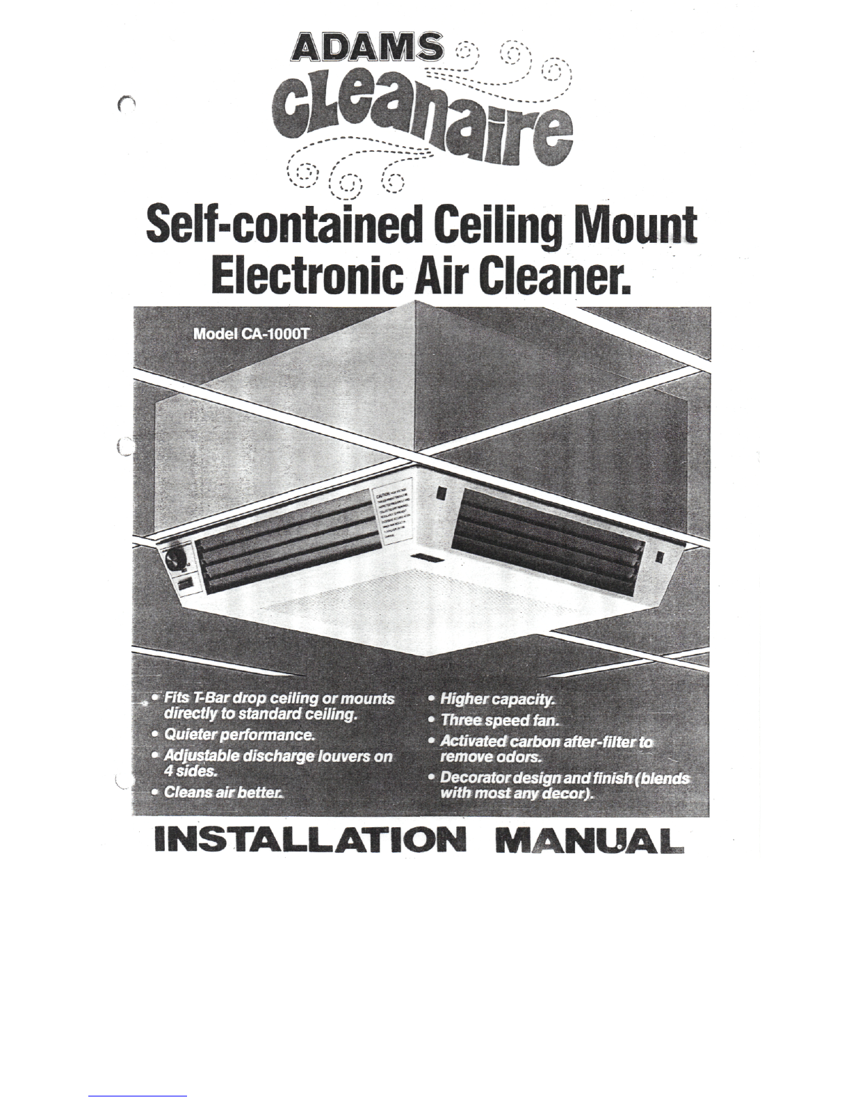
Adams Cleanaire CA-1000T User manual
••
.
'»'"','
•'
,'"*•
•
'^
Self-contained
Ceiling
Mount
Electronic
Air
Cleaner.
Fits
T-Bardrop
ceiling
or
mounts
directly
to
standard
ceiling.
Quieter
performance*
Adjustable
discharge louvers
on
4
sides.
Cleans
ait
better.
Higher capacity.
•
Three speed fan.
•
Activated
carbon
after-filter
t&
remove
odors.
•
Decorator design
and
finish
(blends
with
most
any
decor).
INSTALLATIONMANUAL
GENERAL
This
manual
contains
information
for
location,
installation,
operation
and
service.
Before
installation
and
operation
oftheair
cleaner,
read
instructions
carefully
to
insure
safe
and
effective
operation
of
this
unit,
and
avoidunnecessary
service
cost.
Carefully
unpack
unit
and
check
for
damage
in-
curred
in
shipment.Report
any
damage
to
freight
line
immediately.
Proper
installation
procedures
for
both
T-BAR
ceiling
and
flush
mount
installation
are
pro-
vided.
Follow
method
that
bestsuites
appli-
cation
forair
cleaner.
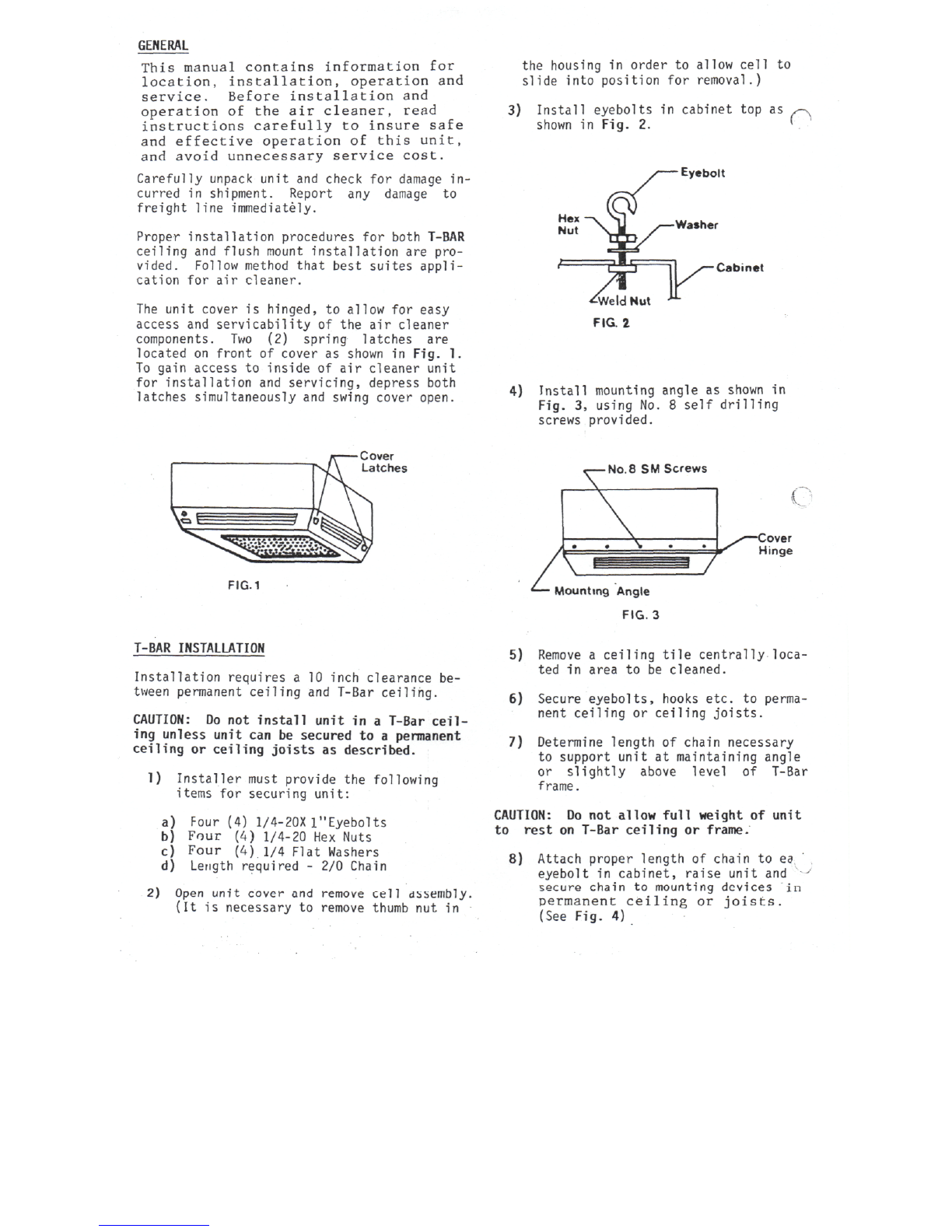
The
unit
cover
is
hinged,
to
allow
for
easy
access
and
servicability
oftheair
cleaner
components.
Two(2)
spring
latches
are
located
on
front
of
cover
as
shown
in
Fig.
1.
To
gain
access
to
inside
ofair
cleaner
unit
for
installation
and
servicing,
depress
both
latches
simultaneously
and
swing
cover
open.
the
housing
in
order
to
allow
cell
to
slide
into
position
for
removal.)
3)
Install
eyebolts
in
cabinet
topas
shown
in
Fig.
2.
Eyebolt
Cabinet
4)
Install
mounting
angle
as
shown
in
Fig.
3,
using
No.8
self
drilling
screwsprovided.
Cover
Latches
FIG.1
No.8
SM
Screws
x>ver
Hinge
Mounting
Angle
FIG.
3
T-BAR
INSTALLATION
Installation
requires
a
10
inch
clearance
be-
tweenpermanent
ceiling
and
T-Bar
ceiling.
CAUTION:
Donot
install
unit
ina
T-Bar
ceil
ing
unlessunit
canbe
secured
toa
permanent
ceiling
or
ceiling
joists
as
described.
1)
Installer
mustprovide
the
following
items
for
securingunit:
a)
Four
(4)
1/4-20X
l"Eyebolts
b)
Four
(4)
1/4-20
Hex
Nuts
c)
Four
(4)1/4
Flat
Washers
d)
Lengthrequired
- 2/0
Chain
2)
Open
unit
cover
and
remove
cell
dbsembly
(Itis
necessary
to
remove
thumb
nutin
5)
Remove
a
ceiling
tile
centrally
loca-
ted
in
area
tobe
cleaned.
6)
Secureeyebolts,hooksetc.
to
perma-
nent
ceiling
or
ceiling
joists.
7)
Determine
length
of
chainnecessary
to
supportunit
at
maintainingangle
or
slightly
above
level
of
T-Bar
frame.
CAUTION:
Donot
allow
full
weight
of
unit
to
rest
on
T-Bar
ceiling
or
frame.
8)
Attach
proper
length
of
chain
to
ea
eyebolt
in
cabinet,
raise
unit
and
'-J
secure
chain
to
mounting
devices
in
permanent
ceiling
or
joists.
(SeeFig.
4)

Permanent
Ceiling
ifff
I f
1
/ / I
/////////.
9
9
*
\ \
i
-~i
y
\
\
'
'
/
\-T-Bar
Ceiling
FIG.
4
rriffiriiirii
Safety
Chain
9)
Connect
electrical
power
toair
clean-
er,
followinginstructionsunder
"Elec-
trical
Wiring".
10)
Remove
charcoal
filter
from
plastic
bag
and
install
in
channel
on
down-stream
side
of
cell.
(Arrow
on
side
of
cell
points
in
thisdirection.)
11)
Re-install
cell,
pre-filters
and
carbon
filter.
12)
Swingaccesscover
upand
snapclosed.
Unit
is
now
ready
to
place
in
opera-
tion.
FLUSH
MOUNT
INSTALLATION
Openunitcover
and
remove
the
pre-
filter
and
cell.
2)
Select
a
locationnear
the
center
of
the
area
tobe
cleaned
and
locate
the
ceiling
joists
in
thatarea.
16"
E]
>—Joist
IK
>—Ceiling
I
i
u
>—Lag
Bolts
FIG.
5
3)
Locate
four
mounting
points
(each
being
ata
joist)
and
pre-drill
holes
into
the
joist
and
unit
housing
as
shown
in
Fig.
5.
4)
Lift
unit
to
ceiling
and
secure
using
four
1/4"
X 2
1/2"
lag
bolts
as
shown
in
Fig.
5.
5)
Connect
electrical
power
to
unit.
See
Field
Wiring
Diagram.
6)
Remove
carbon
filter
from
plastic
bag
and
install
in
guide
rails
on
back
of
cell.
7)
Re-install
cell,
pre-filter
and
carbon
filter.
Replace
thumb-screws
to
secure
cell
in
position.
8)
Close
access
cover
upand
snap
closed.
Unit
is
ready
for
operation.
SYSTEM
CHECKOUT
After
assembly
ingand
installing
the
unit,
switch
the
control
switch
on.
1)The
on/off
light
should
nowbe
on.
The
light
shows
unit
has
line
voltage.
2)
Open
cell
accessdoor.
The
on/
off
light
should
go
out.
The
blower
should
also
stop.
3)
Unit
is
provided
with
three
speed
blower
switch.
Set
switch
to
speed
for
desired
air
flow.
REGULAR
MAINTENANCE
Periodically
the
dirt
collected
by
your
unit
must
be
removed.
The
frequency
of
washing
will
depend
on
the
amount
of
dirt
present
intheair
in
your
application.
The
washing
frequency
best
suited
for
your
unit
canbe
determined
by
examin-
ing
the
collector
cells
attwo
week
intervals.
Asthe
dirt
begins
to
collect,
you
willnotice
a
light
film,
then
a
verydefinite
build-up
will
be
evident
ata
later
inspection.
When
there
isa
noticeable
amount
of
dirt,
collecting
cell
must
be
washed.
In
most
areas
the
collecting
cell
should
be
washedabout
every
12
weeks.
NOTE
:
STEPS
FOR
WASHING
Dirt:
build-up
onthe
ionizing-
collection
cell
should
nothe
confused
with
dirtstains
which
are
normal,
especially
a
yellow-
ish
stain
caused
by.
tobacco
smoke,
and
donot
affect
efficiency.
ELECTRICALWIRING
Electrical
access
panel
is
located
onthe
air
cleanercabinet
assembly.
Knockouts
are
provided
inthetopofthe
housing
assembly.
Wire
the
unit
toa
120
volt,
60HZ,1
phase.
Field
wiring
requires
connectingblack
and
white
leads
to
corresponding
house
current
input.
Connect
incomingground(green)wire
tothe
ground
screw
located
inair
cleaner.
See
Fig.
6.•
120V
Sel.
Sw.
76
24V
Power
Supply
76
1)
Switch
controlswitch
to
"OFF".
2)
Remove
pre-filter
and
cell.
(Donot
washcharcoalpost-
(
filter).
3)
Placecomponents
in
automatic
dishwasher,
stationary
tub,
shower
stall
or
over
floordrain.
Use
hot
soapywater
and
rinse
thoroughly.
Toaid
drying,
rinse
withclear,
hot
water.
Allowcomponents
todry
thoroughly.Handle
the
cells
with
care
to
avoiddamaging
plates
and
ionizing
wires.
4)
Replacepre-filter
and
cell.
(Replacecharcoalfilter).
5)
Closeunitcover.
6)
Switch
control
switch
to
"ON".
If
arcingnoiseoccurs
dueto
wet
cells,turnswitch
offand
allow
more
dryingtime.
SERVICE
WARNING:
Servicingunit
may
expose
hazardouslive
parts.
Disconnect
powerbeforeproceeding.
0
Unnecessary
servicecalls
and
cost
to
customer
maybe
avoided
by
being
familiar
with
some
common
complaints
customers
havewithtypical
operation
ofan
electronic
air
cleaner.
ARCING
(SNAPPING
OR
CRACKING
NOISE)
An
occasional
arcing
emitted
from
theair
normal
andis
caused
of
dirt
entering
the
An
arcingnoise
may
noise
maybe
cleaner.This
is
by
a
largepiece
collect
ing
cell,
also
be
notedafter
cell
washing.
If
this
occurs
andis
constant,allow
more
time
forthe
cell
to
dry.(Refer
to
servicechecklist).
Hi
Volt
Contact
FIG.
6 -
WIRING
DIAGRAM
HUMMING
NOISE
OZONE
The
ionizing
wireshave
a
tendency
to
vibrate
when
charged.
At
timeswhen
atmospheric
conditions
are
just
right
c.
O
the
humidity
is
exceptionally
low,
the
vibration
is
increased
tothe
point
where
an
audible
hummaybe
noted.
It
usually
occursmore
inthe
northern
sections
ofthe
countryduring
the
wintermonths.Thiscondition
canbe
aggravated
ifthe
ionizing-collecting
cell
is
verydirty.
The
condition
is
self-correcting
when
the
relative
humidity
is
increased
orcanbe
allevia
ted
by
washing
the
cell.
Under
normaloperatingconditions
all
electrostatic
air
cleanerspro-
duceminimalquantities
of
ozone
as
a
by-product,
asdo
televisions
and
otherelectricalappliances.
The
design
ofthe
unit
has
beentested
and
isfar
below
the
publishedper-
missible
limits.
The
level
of
sensitivity
(when
itis
noticed)
varies
fromindividual
to
individual.
A
new
unitwillgeneratemoreozone
than
one
that
has
been
in
operation
for
severalweeks.This
isdueto
the
normal
amount
of
sharp
corners
or
manufacturing
burrs
onthe
collect-
ing
cellplates.
The
highvoltage
works
on
theseareas
and
tends
to
roundthem
off
correcting
the
situation.
An
ionizing-collectingcellthat
has
beendamaged,where
the
designed
spacingbetweenelectricallycharged
and
groundplates
has
been
narrowed,
may
alsoproduce
a
greater
amount
of
ozone.For
operationalproblemsother
thanthesecovered
above.
(Refer
to
referencetrouble
chart).
CAUTION:
-
EXERCISEUSUALPRECAUTIONS
WHEN
WORKING
WITH
HIGH
VOLTAGE.
-
WHEN
THE
CIRCUIT
HAS
BEEN
DE-ENERGIZED,
ALWAYSDISCHARGE
ANY
RESIDUALCURRENT
IN
THE
SECONDARY
WITH
AN
INSULATED
HANDLE
SCREWDRIVER.
-
ALWAYSGROUNDPOWERSUPPLY
AND
IONIZ-
ING-COLLECTIN6CELLWHENBENCH
TESTING.
0
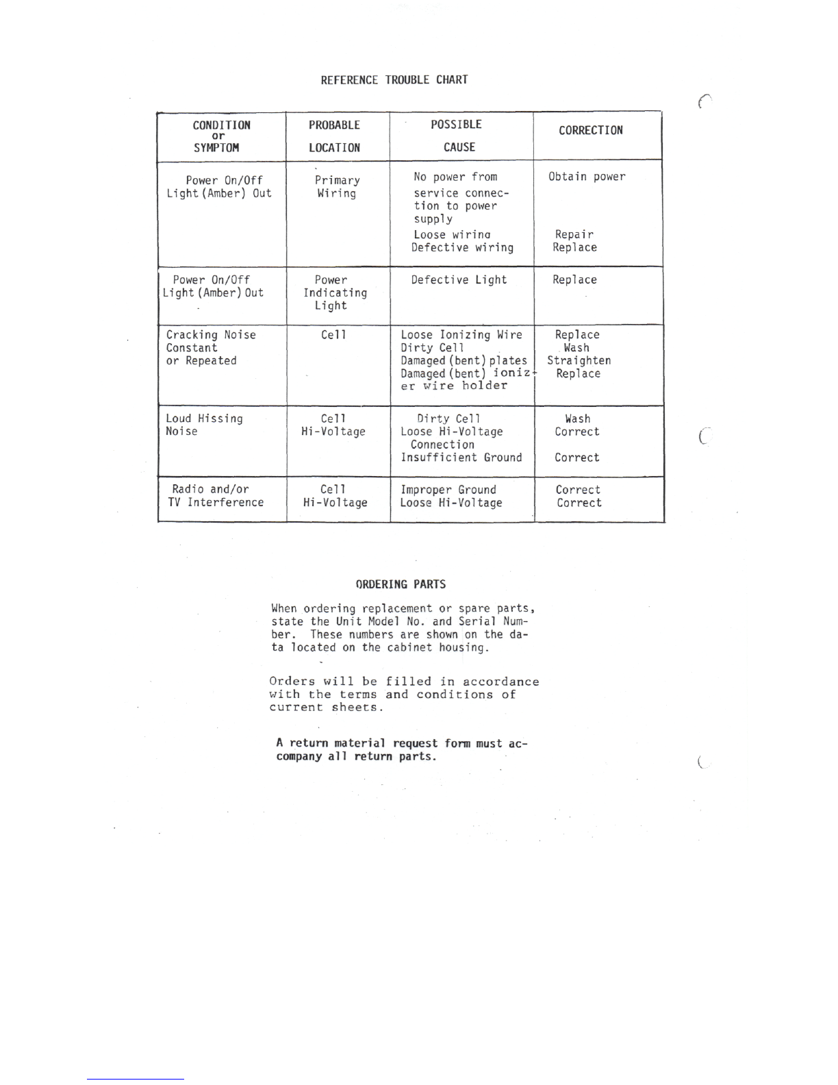
REFERENCETROUBLECHART
r
CONDITION
or
SYMPTOM
Power
On/Off
Light
(Amber)
Out
Power
On/Off
Light
(Amber)
Out
Cracking
Noise
Constant
or
Repeated
Loud
Hissing
Noise
Radio
and/or
TV
Interference
PROBABLE
LOCATION
Primary
Wiring
Power
Indicating
Light
Cell
Cell
Hi-Voltage
Cell
Hi
-Voltage
POSSIBLE
CAUSE
No
powerfrom
serviceconnec-
tion
to
power
supply
Loose
wirina
Defectivewiring
DefectiveLight
LooseIonizingWire
Dirty
Cell
Damaged
(bent)plates
Damaged
(bent)
ioniz
er
wire
holder
Dirty
Cell
Loose
Hi-Voltage
Connection
InsufficientGround
Improper
Ground
Loose
Hi-Voltage
CORRECTION
Obtain
power
Repair
Replace
Replace
Replace
Wash
Straighten
Replace
Wash
Correct
Correct
Correct
Correct
(
ORDERING
PARTS
When
ordering
replacement
or
spare
parts,
state
the
Unit
Model
No.and
Serial
Num-
ber.
These
numbers
are
shown
ontheda-
ta
located
onthe
cabinet
housing.
Orders
will
be
filled
in
accordance
with
the
terms
and
conditions
of
currentsheets.
A
return
material
request
form
must
ac-
company
all
return
parts.
c

r
u
ITEM
1
2
3
4
5
6
7
8
9
10
11
12
13
14
15
PARTSLIST
DESCRIPTION
CabinetCover
CollectorCell
Light
SelectorSwitch
Knob
Latch
LatchActuator
Pre-Filter
Motor
Fan
Blade
Power
Supply
CoverPlate
Ionizing
Wire
Charcoal
Filter
LouvreAssy.
PARTSNUMBER
C21121
C21123
H472
C21112
C21130
C21111
C21110
C21113
'
C21124
C21125
AP24
C21134
C21056
C21114
C21122
QUANTITY
1
1
1
1
1
2
2
1
1
1
1
1
16
1
4
Table of contents


