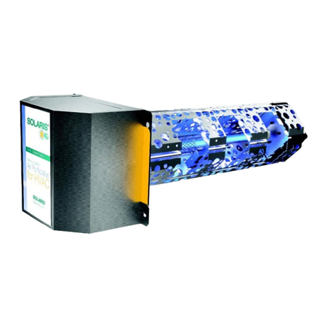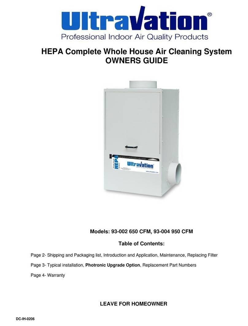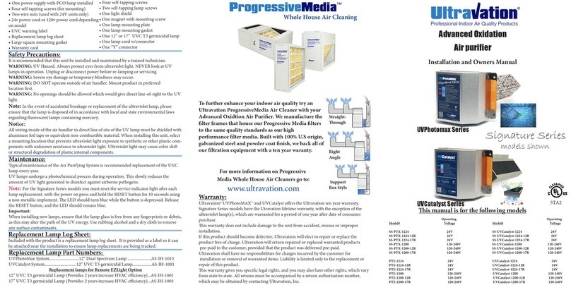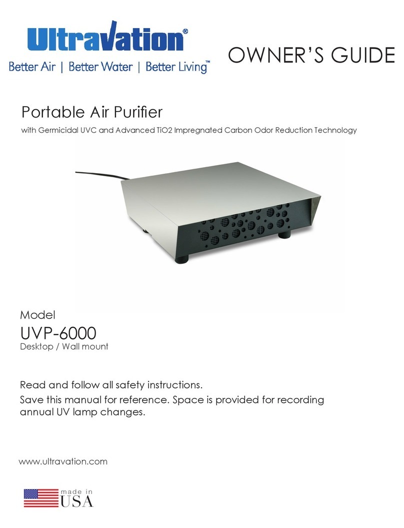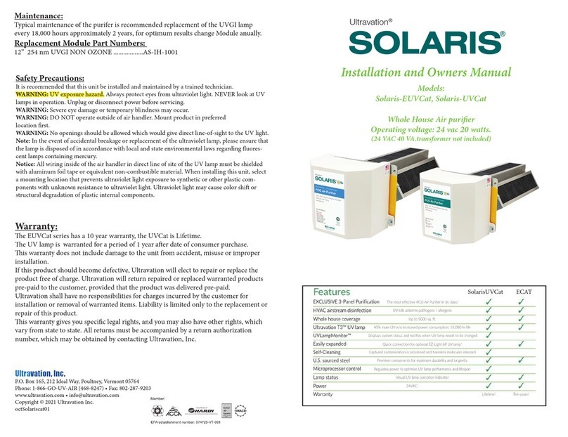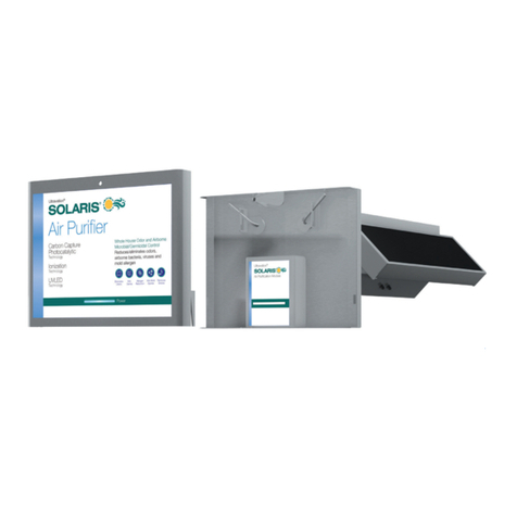
• One SLXECAT Pco Catalyst
• One square mounting gasket
• One power cord
• Four self tapping screws
• One 12” T3 Lamp Module
• Two wire nuts
• UVC warning label, glow plug.
• Replacement lamp log sheet
• Warranty card
• Ductboard plate / sealing tape
• Warning label
Package Contents:
Safety Precautions:
It is recommended that this unit be installed and maintained by a trained technician.
WARNING: UV Hazard. Always protect eyes from ultraviolet light. NEVER look at UV
lamps in operation. Unplug or disconnect power before re-lamping or servicing.
WARNING: Severe eye damage or temporary blindness may occur.
WARNING: DO NOT operate outside of air handler. Mount product in preferred
location rst.
WARNING: No openings should be allowed which would give direct line-of-sight to the
UV light.
In the event of accidental breakage or replacement of the ultraviolet lamp, please ensure
that the lamp is disposed of in accordance with local and state environmental laws re-
garding uorescent lamps containing mercury.
Notice:
All wiring inside of the air handler in direct line of site of the UV lamp must be shielded
with aluminum foil tape or equivalent non-combustible material. When installing this
unit, select a mounting location that prevents ultraviolet light exposure to synthetic or
other plastic components with unknown resistance to ultraviolet light. Ultraviolet light
may cause color shi or structural degradation of plastic internal components.
Installation Steps:
1. Determine a suitable location to install the module. Mounting location should be of
sucient strength as to support the module; otherwise reinforcement of the supplied duct
work collar may be necessary. e module should be installed aer ltration and before
any branches in the duct work.
2. When a suitable location is determined cut a hole for installation of the module.
3. Install supplied ductboard plat - or use as a template for cutting clearance hole:
4. Install a dedicated 40 VA 24 VAC transformer per applicable local and state electrical
codes, not included. Or use optional 120v wall plug accessory sold separately
(Part number 94-135)
5. e Solaris ECat PCO is designed to operate constantly, it is not
b recommended to switch o and on with the fan motor.
6. Connect the power cord using the supplied wire nuts to the transformer.
7. Plug the connector into the UVC module.
8. Ax all warning and lamp replacement labels as well as the UVC viewport in a clear
and logical location for quick inspection of the UVC system.
9. Replace any service panels, reconnect system power.
10. Ensure the system is operating by noting the blue glow within the viewport.
Ultravation, Inc.
P.O. Box 165, 212 Ideal Way, Poultney, Vermont 05764
Phone: 1-866-GO-UV-AIR (468-8247) • Fax: 802-287-9203
www.ultravation.com • info@ultravation.com
Copyright © 2021 Ultravation Inc.
Note: Typical installation locations are aer ltration and before any
branching o into the living area. (Shown in picture above)


