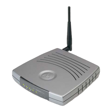
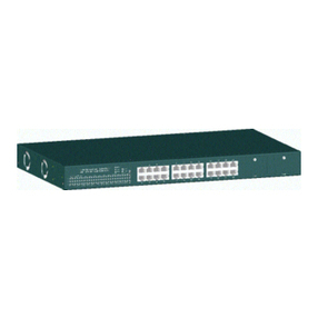
ADC Kentrox 78220 User manual

D-SERV®DSU/CSU
Operator Manual
Stand-alone Models
78220, 78222, 78240
and 78242
Plug-In Models
78210 and 78230
Data Service Units/
Channel Service Units
Document 5000211

Copyright © 1993, 2001 by Kentrox, LLC. All rights reserved.
Printed in the U.S.A.
Specifications published here are current or planned as of the date
of publication of this document. Because we are continuously
improving and adding features to our products, Kentrox reserves
the right to change specifications without prior notice. You may
verify product specifications by contacting our office.
In no event shall Kentrox be liable for any damages resulting from
loss of data, loss of use, or loss of profits. Kentrox further disclaims
any and all liability for indirect, incidental, special,
consequential or other similar damages. This disclaimer of liability
applies to all products, publications and services during and after
the warranty period.
Revision
History
Part # Date Description
65-782001041993 Issue 4
5000211 December, 2001 Issue 5
TrademarkKentrox, D-SERV and DataSMART are registered trademarks of
InformationKentrox, LLC.
All other product names are trademarks or registered trademarks of
their respective owners.
Who to call forIf you need assistance with this product or have questions not
Assistanceanswered by this manual, please visit our Support page on the
Kentrox Web site. You are also welcome to call or send email to our
Technical Assistance Center. Please have your product’s software
revision and hardware serial numbers available to give to the
Support representative. All product returns must include a Return
Authorization number, which you can obtain by calling the Technical
Assistance Center.
The numbers listed below are current at the time of publication.
See the Kentrox Web site for detailed contact and warranty
information.
1-800-733-5511 (continental USA only)
1-503-350-6001
email: [email protected]
http://www.kentrox.com

Contents
1 INTRODUCTION ........................ 1
GeneralDescription..................... 1
Features ......................... 2
Specifications ...................... 3
2CONFIGURATION ....................... 4
DIP Switch Location and Access ............. 5
DIPSwitchConfigurationOptions ............ 6
SwitchS2—DataPortBitRate............ 6
Switch S2 — Data Port LOS Processing ....... 9
SwitchS4—StartingDS0ChannelSelection....10
Switch S4 — Alternating and Contiguous Channels 12
Switch S5 — Advanced Data Port Configuration . . 14
DataInversion....................14
DataPortClockSource ..............14
DataPortClockInversion .............14
Switch S3 — Network Interface Configuration . . . 16
SwitchS3—NetworkInterfaceClockSource....17
SwitchS3—AlarmDe-ActivationTime .......18
LineBuildOut(LBO)Switches ............19
Jumper Location and Access ...............20
JumperConfigurationOptions ..............21
ConfigurationWorkSheet .................22
Operator's Manual
i

3INSTALLATION........................ 23
InstallationCheckList .................. 23
InstallingD-SERVStand-AloneUnits........ 23
InstallingD-SERVPlug-InUnits........... 23
Accessories ...................... 24
Cables ....................... 24
TailCircuitTimingCables ............ 24
DataPortAdapters ................ 25
Shelf and Mounting Accessories ........ 25
SiteSelection ..................... 26
After Unpacking .................... 26
Mounting .......................... 27
DesktopMounting................... 27
ElectricalInstallation ................... 28
Stand-AloneACPowerConnection......... 28
Stand-AloneDCPowerConnections ........ 28
Stand-Alone Alarm Relay Connections (optional) 29
Stand-Alone Power/Alarm Connector Installation 29
Plug-InPowerandAlarmConnections....... 29
SelfTest ........................ 30
DataPortConnection................. 31
TailCircuitTimingSetUp .............. 32
NetworkConnection ................. 34
Operator's Manual
ii

4OPERATION ..........................36
FrontPanelOperation ...................36
LEDs ...........................36
LoopBackSwitch....................38
LineLoopBack(LLB) ...............38
DataPortLoopBack(DPLB) ...........39
RemoteOperation......................40
RemoteLoopBacks ..................41
Figures
Figure1.DIPSwitchLocations .............. 4
Figure2.LegRemoval ................... 5
Figure3.DIPSwitchPositions .............. 5
Figure4.S2Location.................... 6
Figure5.S2Location.................... 9
Figure6.S4Location....................11
Figure7.S4Location....................13
Figure8.S5Location....................15
Figure9.S3Location....................16
Figure10.S3Location ...................18
Figure11.LBOSwitches..................19
Figure12.ConfigurationJumperLocation........20
Figure13.ScrewsforCaseSeparation..........21
Figure 14. Stand-Alone DC Power/Alarm Connector . . 29
Figure15.V.35andEIA-530DataPortLocation ....30
Operator's Manual
iii

Figure 16. Tail Circuit Timing (TCT) Application . . . 32
Figure 17. Cable #95010055 Pin Outs .......... 32
Figure 18. Cable #95010056 Pin Outs .......... 33
Figure 19. Cable #95010057 Pin Outs .......... 33
Figure 20. Cable #95010058 Pin Outs .......... 33
Figure 21. Network Port Location (AC Powered Units) 35
Figure 22. Network Port Location (DC Powered Units) 35
Figure23.RJ48CPinDesignation............ 35
Figure24.D-SERVFrontPanel ............. 37
Figure25.LineLoopBack(LLB) ............ 38
Figure26.DataPortLoopBack(DPLB) ........ 39
Figure 27. D-SERV Main Menu (MM) ........... 40
Figure28.D-SERVLowerMenu(LM) .......... 41
Figures (cont)
Operator's Manual
iv

REGULATORY INFORMATION
ADC Kentrox D-SERV units have been tested by a Nationally Recognized
Testing Laboratory (NRTL) and are in compliance with Underwriters
Laboratories (UL) standard 1459, Edition 2.
FCC PART 15 REQUIREMENTS
This equipment has been tested and found to comply with the limits for a Class
A digital device, pursuant to Part 15 of the FCC Rules. These limits are
designed to provide reasonable protection against harmful interference when the
equipment is operated in a commercial environment. This equipment generates,
uses and can radiate radio frequency energy and, if not installed and used in
accordance with the instruction manual, may cause harmful interference to radio
communications. Operation of this equipment in a residential area is likely to
cause harmful interference in which case the user will be required to correct the
interference at his own expense.
Operator's Manual
v

FCC PART 68 REQUIREMENTS
This equipment complies with Part 68 of the FCC rules. On the bottom of this
equipment is a label that contains, among other information, the FCC
registration number and ringer equivalence number (REN) for this equipment.
Upon request of the telephone company, you should provide the FCC
registration number and the ringer equivalence number (REN) of the equipment
which is connected to your line. The D-SERV DSU/CSUs registration number is
F8IUSA-74432-DE-N and the REN is 0.0B.
The D-SERV DSU/CSU operates with a 1.544 Mbit/s/s digital channel using an
RJ48C USOC 8-pin modular connector on the back of the D-SERV unit.
The REN is used to determine the quantity of devices which may be connected
to the telephone line. Excessive REN’s on the telephone line may result in the
devices not ringing in response to an incoming call. In most, but not all areas,
the sum of the REN’s should not exceed five (5.0). To be certain of the number
of devices that may be connected to the line, as determined by the total REN’s
contact the telephone company to determine the maximum REN for the calling
area.
The service code is 6.0N. The Facility Interface Code is 04DU9-C for lines using
the Extended Super Frame format, 04DU9-B for lines using the Super Frame
format, and 04DU9-S for lines using the B8ZS format. All D-SERV models
connect to the network using an RJ48C connector.
The telephone company must be notified before removal of a D-SERV DSU/CSU
connected 1.544 Mbit/s/s digital service. If the telephone company notes a
problem they may temporarily discontinue service, and will notify you of this
disconnection. (If advance notice is not feasible, you will be notified as soon as
possible.) When you are notified you will be given the opportunity to correct the
problem and informed of your right to file a complaint with the FCC.
The telephone company may make changes in its facilities, equipment,
operations, or procedures that could affect the operation of the equipment. If this
happens, the telephone company will provide advance notice in order for you to
make the necessary modifications in order to maintain uninterrupted service.
Normally, the D-SERV DSU/CSU will be used in conjunction with FCC registered
equipment that limits the Encoded Analog Content and provides the required
Billing Protection. If the connected equipment is not of this type, an affidavit
must be supplied to the telephone company where the network connection is to
be made. The affidavit is to be notarized, and is to be filed at least ten days
before the initial connection.
If trouble is experienced with this equipment (the D-SERV DSU/CSU), please
contact the Customer Service Department, Kentrox Industries for repair and
warranty information.
Contiguous 48 states including Oregon:1-800-733-5511
Elsewhere: 1-503-643-1681
If the trouble is causing harm to the telephone network, the telephone company
may request you remove the equipment from the network until the problem is
resolved.
All repairs should be handled by authorized Kentrox Service Personnel.
Operator's Manual
vi

Equipment Attachment Limitations
CP-01
1.10.1
“NOTICE: The Canadian Department of Communications label identifies certified
equipment. This certification means that the equipment meets certain
telecommunications network protective, operational and safety requirements.
The department does not guarantee the equipment will operate to the user’s
satisfaction.
Before installing this equipment, users should ensure that it is permissible to be
connected to the facilities of the local telecommunications company. The
equipment must also be installed using an acceptable method of connection. In
some cases, the company’s inside wiring associated with a single line individual
service may be extended by means of a certified connector assembly (telephone
extension cord). The customer should be aware that compliance with the above
conditions may not prevent degradation of service in some situations.
Repairs to certified equipment should be made by an authorized Canadian
maintenance facility designated by the supplier. Any repairs or alterations made
by the user to this equipment, or equipment malfunctions, may give the
telecommunications company cause to request the user to disconnect the
equipment.
Users should ensure for their own protection that the electrical ground
connections of the power utility, telephone lines and internal metallic water pipe
system, if present, are connected together. This precaution may be particularly
important in rural areas.
CAUTION: Users should not attempt to make such connections
themselves, but should contact the appropriate electric inspection
authority, or electrician, as appropriate."
CP-01
1.10.2
“The Load Number (LN) assigned to each terminal device denotes the
percentage of the total load to be connected to a telephone loop which is used
by the device, to prevent overloading. The termination on a loop may consist of
any combination of devices subject only to the requirement that the total of the
Load Numbers of all the devices does not exceed 100.”
Operator's Manual
vii

Canadian DOC Requirements
This digital apparatus does not exceed the Class A limits for radio noise
emissions from digital apparatus as set out in the Radio Interference
Regulations of Canada.
Le présent appareil numérique n’émet pas de bruits radioélectriques dépassant
les limites applicables aux appareils numériques Classe A prescrite dans le
règlement sur le brouillage Radioélectrique Édicté par Communications du
Canada.
Operator's Manual
viii

1INTRODUCTION
General Description
The Kentrox D-SERV DSU/CSU is a low cost, intelligent, single port
T1 DSU/CSU that provides channelized connections to T1 or
Fractional T1 (FT1) services. The serial data signal can operate in
increments of 56 Kbit/s or 64 Kbit/s, up to the full band width of
1.536 Mbit/s. The network T1 signal is always 1.544 Mbit/s. The CSU
portion of the D-SERV DSU/CSU insures that the signal is compatible
in format and pulse density with T1 requirements. The D-SERV
DSU/CSU provides line protection from voltage spikes, surges and
line crossings coming from the public network. In addition, the
D-SERV DSU/CSU generates alarm signals and performs loop backs
to aid in the turn up and trouble-shooting of expensive T1 circuits.
The D-SERV family of products includes models:
78220 D-SERV DSU/CSU Stand-Alone Unit, -24 to -48 VDC, with
aV.35DataPort
78222 D-SERV DSU/CSU Stand-Alone Unit, 110 VAC, with a
V.35 Data Port
78240 D-SERV DSU/CSU Stand-Alone Unit, -24 to -48 VDC, with
an EIA-530 Data Port
78242 D-SERV DSU/CSU Stand-Alone Unit, 110 VAC, with an
EIA-530 Data Port
78210 D-SERV DSU/CSU Plug-In card, -24 to -48 VDC, with a
V.35 Data Port
78230 D-SERV DSU/CSU Plug-In card, -24 to -48 VDC, with an
EIA 530 Data Port
78260 D-SERV 12-slot high density mounting chassis
78255 D-SERV 2-unit rack mounting tray
Operator's Manual
1

Features
The D-SERV DSU/CSU is available with the following features:
¤DIP switch selectable configuration
¤Choice of V.35 Data Port or EIA-530 Data Port
¤Choice of an internal -24 to -48 VDC or 110 VAC power
supply
¤Normally Open or Normally Closed Alarm Relay contacts
(DC versions only)
¤Diagnostics through front panel switch controlled loop backs
¤Remote report and alarm retrieval from a DataSMART unit
¤Remote diagnostics capability from a DataSMART unit
¤Data Port Timing
¤Front Panel Status and Alarm LEDs
¤RJ48C Network interface connector
¤Ability to easily convert Stand-Alone units into Plug-In
shelf units — DC Powered units only!
¤12-slot chassis will fit 19" or 23" equipment racks
Operator's Manual
2

Specifications
Network Interface
Line Rate T1 (1.544Mbit/s)
Framing SF/ESF (selectable)
Line Code AMI/B8ZS (selectable)
Bit Stuffing Enable/Disable 15 zero suppression
Input Signal DSX-1 from 0dB to -27dB Typical
Output Signal DSX-1 with LBO 0
Data Port Interface
Bit Rate N x 56 kbit/s or N x 64 kbit/s
(N= 1 through 24)
Electrical V.35 or EIA-530 (RS-422/449)
Power
DCPower 22to56VDC,6W
AC Power 105 to 130 VAC, 57 to 63 Hz, 8 W
Mechanical Specifications
Stand-Alone Size (with feet) 1.93" high x 8.35" wide x 12.0" deep
Stand-Alone Size (without feet) 1.6" high x 8.0" wide x 12.0" deep
Weight 2.47 lb.
12-slot Chassis Size 7.0" high x 17.0" wide x 12.0" deep
Environmental
Operating Temperature 0-50° C
Relative Humidity 5% to 95% RH
Compatibility
AT&T 62411
AT&T 54016
ANSI T1.403
Remote Loop Back Code Compatibility
Line Loop Back Inband — Set LLB (10000) Reset (100)*
Out-of-Band — T1.403 codes*
Data Port Loop Back Inband — Set DPLB (127 code)
Reset (inverted 127 code)*
Payload Loop Back Out-of-Band —TR 54016 or
T1.403 codes*
*Remote loop backs can be reset by toggling the D-SERV front panel loop back switch.
Operator's Manual
3

2CONFIGURATION
The majority of configuration options are set through the DIP
switches. A few special configuration options are available through
jumpers inside the unit.
If a DataSMART DSU is connected at the far end of the network some
report and alarm configuration options can be configured using the
ARC help menu. Refer to Section 4, Operation for details on use of
the ARC help menu.
A Configuration Work Sheet is provided at the end of this section to
help plan configuration and to record which configuration settings
have been made.
Figure 1. DIP Switch Locations
Operator's Manual
4

DIP Switch Location and Access
The DIP switches are located on the sides of the D-SERV card.
Plug-in units have the switches readily accessible.
To access the switches on a stand-alone unit:
¤Disconnect all power connections and interface cables
¤Turn the D-SERV unit over, and using a phillips
screwdriver remove the four screws attaching the legs to the
case and remove the legs (see Figure 2)
¤Set the DIP switches
¤Reattach the legs
Figure 2. Leg Removal
Figure 3. DIP Switch Positions
Operator's Manual
5

DIP Switch Configuration Options
Switch S2 — Data Port Bit Rate
Up to 24 Network Interface DS0 channels can be assigned to the data
port. Unused channels remain idle.
Switch S2-1 sets the channel data rate to 56 Kbit/s or 64 Kbit/s.
Switches S2-2 through S2-6 set the number of channels to be activated.
NOTE: Any non-defined setting for S2-2 through S2-6 will
select all 24 channels. The channel data rate is still
determined by S2-1.
Figure 4. S2 Location
Operator's Manual
6

Switch S2 — 56 Kbit/s/Channel Data Port Bit Rate Settings
Number
of
Channels
Data
Rate
(Kbit/s)
123456
24 1344 Down Down Down Down Down Down
1 x 56 56 Down Up Down Down Down Down
2 x 56 112 Down Down Up Down Down Down
3 x 56 168 Down Up Up Down Down Down
4 x 56 224 Down Down Down Up Down Down
5 x 56 280 Down Up Down Up Down Down
6 x 56 336 Down Down Up Up Down Down
7 x 56 392 Down Up Up Up Down Down
8 x 56 448 Down Down Down Down Up Down
9 x 56 504 Down Up Down Down Up Down
10 x 56 560 Down Down Up Down Up Down
11 x 56 616 Down Up Up Down Up Down
12 x 56 672 Down Down Down Up Up Down
13 x 56 728 Down Up Down Up Up Down
14 x 56 784 Down Down Up Up Up Down
15 x 56 840 Down Up Up Up Up Down
16 x 56 896 Down Down Down Down Down Up
17 x 56 952 Down Up Down Down Down Up
18 x 56 1008 Down Down Up Down Down Up
19 x 56 1064 Down Up Up Down Down Up
20 x 56 1120 Down Down Down Up Down Up
21 x 56 1176 Down Up Down Up Down Up
22 x 56 1232 Down Down Up Up Down Up
23 x 56 1288 Down Up Up Up Down Up
Operator's Manual
7

Switch S2 — 64 Kbit/s/Channel Data Port Bit Rate Settings
Number
of
Channels
Data
Rate
(Kbit/s)
123456
24 1536 Up Down Down Down Down Down
1 x 64 64 Up Up Down Down Down Down
2 x 64 128 Up Down Up Down Down Down
3 x 64 192 Up Up Up Down Down Down
4 x 64 256 Up Down Down Up Down Down
5 x 64 320 Up Up Down Up Down Down
6 x 64 384 Up Down Up Up Down Down
7 x 64 448 Up Up Up Up Down Down
8 x 64 512 Up Down Down Down Up Down
9 x 64 576 Up Up Down Down Up Down
10 x 64 640 Up Down Up Down Up Down
11 x 64 704 Up Up Up Down Up Down
12 x 64 768 Up Down Down Up Up Down
13 x 64 832 Up Up Down Up Up Down
14 x 64 896 Up Down Up Up Up Down
15 x 64 960 Up Up Up Up Up Down
16 x 64 1024 Up Down Down Down Down Up
17 x 64 1088 Up Up Down Down Down Up
18 x 64 1152 Up Down Up Down Down Up
19 x 64 1216 Up Up Up Down Down Up
20 x 64 1280 Up Down Down Up Down Up
21 x 64 1344 Up Up Down Up Down Up
22 x 64 1408 Up Down Up Up Down Up
23 x 64 1472 Up Up Up Up Down Up
Operator's Manual
8

Switch S2 — Data Port LOS Processing
Some DTE equipment changes the state of the RTS and/or DTR signal
lines on a regular basis which the D-SERV DSU/CSU may interpret as
an LOS condition. Options for determining a data port LOS condition
are if the RTS signal line is de-asserted, the DTR signal line is
de-asserted, or if both of the signal lines are de-asserted at the same
time. The D-SERV DSU/CSU also provides the option of not
monitoring for data port LOS by ignoring the condition of the RTS
and DTR signal lines.
Switches S2-7 and S2-8 configure this option.
NOTE: If a data port LOS condition occurs, all active channels
will transmit All Ones out to the network. All idle
channels will continue to transmit Idle code. If the unit
has been configured for data port timing (tail circuit
timing) the timing source will switch to internal clock
timing.
Switch S2 — Data Port LOS Processing
Function 7 8
RTS Down Down
DTR Up Down
RTS and DTR Down Up
None Up Up
Figure 5. S2 Location
Operator's Manual
9

Switch S4 — Starting DS0 Channel Selection
If fewer than 24 channels have been activated, the user can select
which channel is first. For example, if four channels have been
activated any of the eight channel starting options may be selected.
Unused channels remain idle.
Switches S4-1, S4-2, and S4-3 select the starting channel.
NOTE: It is not allowed to activate more channels than can be
accommodated between the starting channel and the
24th channel. For example, if ten channels have been
activated and channel 16 has been chosen as the
starting channel the D-SERV DSU/CSU will alert the
user of a configuration conflict.
In the event of a conflict the D-SERV DSU/CSU will
flash the front panel POWER, RED ALARM, and DATA
LEDs red. The last valid starting channel selected by
the user is used until the configuration error is
corrected by the operator.
Switch S4 — Starting DS0 Channel Selection
Starting Channel 1 2 3
Channel 1 Down Down Down
Channel 2 Up Down Down
Channel 3 Down Up Down
Channel 4 Up Up Down
Channel 6 Down Down Up
Channel 8 Up Down Up
Channel 12 Down Up Up
Channel 16 Up Up Up
Operator's Manual
10
This manual suits for next models
5
Table of contents
