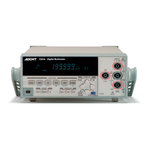
ADCMT 7451A User manual

MANUAL NUMBER
C
Printed in Japan
ADC CORPORATION
All rights reserved.
7451A/61A/61P
Digital Multimeter
Operation Manual
FOE-00000061B00
First printing January 20, 2011
Applicable Models
7451A
7461A
7461P
2011
Cover


Certificate of Conformity
This is to certify, that
complies with the provisions of the EMC Directive, 2004/108/EC in accordance with
EN61326-1.
and Low Voltage Directive, 2006/95/EC in accordance with EN61010.
ADC Corp. ROHDE&SCHWARZ
Japan Europe GmbH
Munich, Germany
instrument, type, designation
7451A/61A/P.00
Digital Multimeter
7451A / 7461A / 7461P
Certificate of Conformity


7451A/7461A/7461P Digital Multimeter Operation Manual
C-1
TABLE OF CONTENTS
1. INTRODUCTION
....................................................................................... 1-1
1.1 Contents of this Manual .................................................................................... 1-1
1.2 Product Overview .............................................................................................. 1-2
2. PRECAUTIONS
.......................................................................................... 2-1
2.1 If a Fault Occurs ................................................................................................ 2-1
2.2 Removing the Case ........................................................................................... 2-1
2.3 Power Fuse ........................................................................................................ 2-1
2.4 Electromagnetic Interference ............................................................................ 2-1
2.5 Note When Turning on the Power .................................................................... 2-2
3. SETUP
............................................................................................................ 3-1
3.1 Inspection on Delivery ...................................................................................... 3-1
3.2 Installation Environment ................................................................................... 3-3
3.2.1 Operating Environment .............................................................................. 3-3
3.2.2 Protecting Against Electrostatic Discharge ................................................ 3-4
3.3 Accessories ........................................................................................................ 3-5
3.3.1 Input Cable ................................................................................................. 3-5
3.3.2 Caution when Connecting Peripherals ....................................................... 3-7
3.4 Power Requirements ......................................................................................... 3-8
3.4.1 Checking the Power Supply Voltage .......................................................... 3-8
3.4.2 Changing the Power Supply Voltage ......................................................... 3-9
3.4.3 Connecting the Power Cable ...................................................................... 3-11
4. QUICK START
............................................................................................ 4-1
4.1 Panel Description .............................................................................................. 4-1
4.1.1 Front Panel Description .............................................................................. 4-1
4.1.1.1 Display Section ........................................................................................... 4-2
4.1.1.2 Power Switch .............................................................................................. 4-2
4.1.1.3 Measurement Function Keys ...................................................................... 4-2
4.1.1.4 Measurement Range Selection Keys .......................................................... 4-3
4.1.1.5 Sampling Selection Keys ............................................................................ 4-3
4.1.1.6 Calculation Selection Keys ......................................................................... 4-3
4.1.1.7 MENU/ENTER Key ................................................................................... 4-3
4.1.1.8 SHIFT/EXIT/LOCAL Key ......................................................................... 4-4
4.1.1.9 Front Input Section for Measurement ......................................................... 4-4
4.1.1.10 CAT II (Marking) ....................................................................................... 4-4
4.1.2 Rear Panel Description ............................................................................... 4-5
4.2 Basic Operation ................................................................................................. 4-6
4.2.1 Measurement Functions .............................................................................. 4-6
4.2.2 Setting the Measurement Range ................................................................. 4-19
4.2.3 Setting the Sampling Rate .......................................................................... 4-19
5. MENU OPERATION AND FUNCTION DESCRIPTION
.............. 5-1
TABLE OF CONTENTS

7451A/7461A/7461P Digital Multimeter Operation Manual
Table of Contents
C-2
5.1 Menu ................................................................................................................. 5-1
5.1.1 How to Navigate the Menus ....................................................................... 5-1
5.1.2 Menu List .................................................................................................... 5-4
5.2 Measurement Functions and Parameters ........................................................... 5-9
5.2.1 DC Voltage Measurement (DCV) .............................................................. 5-9
5.2.2 DC Voltage Measurement (DCV-Bch) ...................................................... 5-9
5.2.3 Continuity Measurement ............................................................................ 5-10
5.2.4 Temperature Measurement ......................................................................... 5-10
5.3 Measurement Range and Auto-Range .............................................................. 5-11
5.3.1 Measurement Function and Range Structure ............................................. 5-11
5.3.2 Auto-range .................................................................................................. 5-12
5.4 Auto-Zero Operation ......................................................................................... 5-13
5.5 Display Mode Setting ........................................................................................ 5-14
5.6 Display Digit Setting ......................................................................................... 5-14
5.7 Sampling Operation .......................................................................................... 5-15
5.7.1 Sampling Interval (SI) and Integration Time (IT) Settings ........................ 5-16
5.7.2 Sampling Count Setting .............................................................................. 5-18
5.8 Trigger Function ................................................................................................ 5-19
5.8.1 Trigger System Operation .......................................................................... 5-20
5.8.2 Trigger Source Selection ............................................................................ 5-21
5.8.3 Trigger Delay (Td) ..................................................................................... 5-23
5.8.4 Trigger Count Setting ................................................................................. 5-24
5.8.5 Level Trigger and Delta Trigger ................................................................. 5-24
5.8.5.1 Level Trigger .............................................................................................. 5-25
5.8.5.2 Delta Trigger .............................................................................................. 5-26
5.8.5.3 Pre-Trigger Operation ................................................................................ 5-28
5.9 Calculation Functions ........................................................................................ 5-29
5.9.1 NULL Calculation ...................................................................................... 5-31
5.9.2 Smoothing Calculation ............................................................................... 5-32
5.9.3 Scaling Calculation ..................................................................................... 5-35
5.9.4 dB and dBm calculation ............................................................................. 5-37
5.9.5 Comparator Calculation .............................................................................. 5-39
5.9.6 MAX/MIN Calculation .............................................................................. 5-42
5.9.7 Statistical Calculation ................................................................................. 5-44
5.10 Saving and Loading the Measurement Condition Settings ............................... 5-46
5.10.1 Auto-Loading when Turning on the Power ................................................ 5-46
5.10.2 Saving the Setting Parameters .................................................................... 5-46
5.10.3 Loading the Setting Parameters .................................................................. 5-46
5.11 Storing and Recalling the Measurement Data ................................................... 5-47
5.11.1 Memory Store ............................................................................................. 5-47
5.11.2 Memory Recall ........................................................................................... 5-47
5.11.3 Memory Clear ............................................................................................. 5-47
5.12 System Settings ................................................................................................. 5-48
5.12.1 Buzzer Setting ............................................................................................ 5-48
5.12.2 Selecting the Input Terminal ...................................................................... 5-48
5.12.3 Disabling Functions .................................................................................... 5-48
5.12.4 Front Panel Disabling Function .................................................................. 5-50
5.12.5 Error Queue ................................................................................................ 5-52

7451A/7461A/7461P Digital Multimeter Operation Manual
Table of Contents
C-3
6. HOW TO USE THE INTERFACE
......................................................... 6-1
6.1 Interface Selection ............................................................................................. 6-1
6.1.1 Response to the *IDN? Command (7451A/61A Only) .............................. 6-1
6.2 GPIB .................................................................................................................. 6-3
6.2.1 Overview .................................................................................................... 6-3
6.2.2 Precautions in Use of GPIB ........................................................................ 6-4
6.2.3 GPIB Setting ............................................................................................... 6-5
6.3 USB ................................................................................................................... 6-7
6.3.1 Overview .................................................................................................... 6-7
6.3.2 USB Specifications ..................................................................................... 6-7
6.3.3 Setting Up the USB Port ............................................................................. 6-7
6.3.3.1 Connecting to a Personal Computer ........................................................... 6-7
6.3.3.2 USBid Setting ............................................................................................. 6-8
6.4 Control Signal ................................................................................................... 6-8
6.4.1 External Trigger Terminal (TRIGGER IN) ................................................ 6-8
6.4.2 Measurement Complete Signal Terminal (COMPLETE OUT) ................. 6-9
6.5 Comparator Output ............................................................................................ 6-11
6.6 Digital Output (7461P Only) ............................................................................. 6-13
6.7 Command Reference ......................................................................................... 6-15
6.7.1 Selecting the Command Language ............................................................. 6-15
6.7.1.1 Compatibility .............................................................................................. 6-15
6.7.2 Output Data Format .................................................................................... 6-16
6.7.3 ADC Command Reference ......................................................................... 6-22
6.7.4 SCPI Command Reference ......................................................................... 6-35
6.7.4.1 SCPI Command Reference Syntax ............................................................. 6-35
6.7.4.2 Remote Command ...................................................................................... 6-37
6.7.5 Status Register Structure ............................................................................ 6-45
6.8 Sample Programs (Command used in ADC CORPORATION) ....................... 6-55
6.9 Sample Programs (SCPI command) .................................................................. 6-59
7. SPECIFICATIONS
...................................................................................... 7-1
7.1 Specifications .................................................................................................... 7-1
7.1.1 DC Voltage Measurement (DCV) .............................................................. 7-1
7.1.2 AC Voltage Measurement (ACV, ACV(AC+DC)) .................................... 7-3
7.1.3 Resistance Measurement (2W, LP-2W, 4W, LP-4W) ................... 7-7
7.1.4 DC Current Measurement (DCI) ................................................................ 7-10
7.1.5 AC Current Measurement (ACI, ACI(AC+DC)) ....................................... 7-11
7.1.6 Frequency Measurement (FREQ) ............................................................... 7-14
7.1.7 Diode Measurement .................................................................................... 7-15
7.1.8 Continuity Measurement ............................................................................ 7-16
7.1.9 Temperature Measurement (TEMP-2W, TEMP-3W, TEMP-4W) ............ 7-16
7.1.10 Measurement Time and Display Digits ...................................................... 7-17
7.1.11 Calculation Functions ................................................................................. 7-19
7.2 Interface Specifications ..................................................................................... 7-20
7.3 General Specifications ...................................................................................... 7-21
7.4 Options .............................................................................................................. 7-22

7451A/7461A/7461P Digital Multimeter Operation Manual
Table of Contents
C-4
8. MAINTENANCE
........................................................................................ 8-1
8.1 Replacing Fuses ................................................................................................ 8-1
8.1.1 Replacing a Power Fuse ............................................................................. 8-2
8.1.2 Replacing a Protection Fuse ....................................................................... 8-2
8.2 Cleaning ............................................................................................................ 8-3
8.2.1 Cleaning the Outside .................................................................................. 8-3
8.2.2 Cleaning Others .......................................................................................... 8-3
8.3 Calibration ......................................................................................................... 8-4
8.3.1 Preparing for Calibration ............................................................................ 8-4
8.3.2 Calibration Standards ................................................................................. 8-4
8.3.3 Calibration Point ......................................................................................... 8-5
8.3.4 Calibration Procedure ................................................................................. 8-8
8.4 Replacing Parts with Limited Life .................................................................... 8-11
8.5 Product Disposal and Recycle ........................................................................... 8-12
8.6 Storage ............................................................................................................... 8-14
8.7 Transportation ................................................................................................... 8-14
8.8 Notes Regarding Repair, Replacement, and Periodic Calibration .................... 8-14
8.8.1 Contacting ADC CORPORATION for Repair or Calibration ................... 8-14
8.8.2 Address and Phone Number ....................................................................... 8-14
8.9 System Recovery Procedure ............................................................................. 8-15
8.10 Self-Test ............................................................................................................ 8-19
8.10.1 Self-Test ..................................................................................................... 8-19
8.10.2 Display and Key Tests ................................................................................ 8-19
8.11 Error Message List ............................................................................................ 8-21
DIMENSIONAL OUTLINE DRAWING
........................................................... EXT-1
ALPHABETICAL INDEX
..................................................................................... I-1

F-1
7451A/7461A/7461P Digital Multimeter Operation Manual
LIST OF ILLUSTRATIONS
No. Title Page
3-1 Operating Environment ..................................................................................................... 3-3
3-2 Electrostatic Countermeasures for the Work Floor and Human Body ............................. 3-4
3-3 Electrostatic Countermeasures for the Workbench .......................................................... 3-4
3-4 Indication of the Set Power Supply Voltage ..................................................................... 3-8
3-5 Connecting the Power Cable ............................................................................................. 3-11
4-1 Front Panel Description ....................................................................................................4-1
4-2 Display Section Description ............................................................................................. 4-2
4-3 Rear Panel Description .....................................................................................................4-5
4-4 DC Voltage Measurement (DCV) .................................................................................... 4-6
4-5 DC Voltage Measurement (DCV-Bch) ............................................................................. 4-7
4-6 AC Voltage Measurement (ACV and ACV(AC+DC)) .................................................... 4-9
4-7 Resistance Measurement (2W, 4W, LP-2W, and LP-4W) ................................... 4-10
4-8 DC Current Measurement (DCI) ...................................................................................... 4-11
4-9 AC Current Measurement (ACI and ACI(AC+DC)) ........................................................ 4-13
4-10 Continuity Measurement ................................................................................................... 4-14
4-11 Diode Measurement .......................................................................................................... 4-15
4-12 Frequency Measurement (FREQ) ..................................................................................... 4-16
4-13 Temperature Measurement ............................................................................................... 4-18
5-1 Menu Operation ................................................................................................................ 5-1
5-2 Measurement Sequence .................................................................................................... 5-15
5-3 Trigger Model ................................................................................................................... 5-19
5-4 Level Trigger .................................................................................................................... 5-25
5-5 Delta Trigger ..................................................................................................................... 5-26
5-6 Delta Trigger ..................................................................................................................... 5-27
5-7 Calculation System Diagram ............................................................................................ 5-30
6-1 Simple Equivalent Circuit of Trigger Input Terminal ...................................................... 6-8
6-2 Simple Equivalent Circuit of Complete Signal Output Terminal ..................................... 6-9
6-3 Signal Output Pin .............................................................................................................. 6-11
6-4 Status Register Structure (1/2) .......................................................................................... 6-46
6-5 Status Register Structure (2/2) .......................................................................................... 6-47
6-6 Status Byte Register Structure .......................................................................................... 6-48
8-1 Input Terminal Protection Fuse ........................................................................................ 8-2


T-1
7451A/7461A/7461P Digital Multimeter Operation Manual
LIST OF TABLES
No. Title Page
3-1 Standard Accessories ........................................................................................................ 3-2
3-2 ESD Countermeasures ...................................................................................................... 3-4
3-3 Accessories ....................................................................................................................... 3-5
3-4 Relation Table between AC Power Supply Voltage and Indication of Set Power Supply Voltage 3-8
4-1 Maximum Allowable Applied Voltage (DCV) ................................................................ 4-6
4-2 Range and Input impedance (DCV) .................................................................................. 4-6
4-3 Maximum Allowable Applied Voltage (DCV-Bch) ......................................................... 4-7
4-4 Range and Input impedance .............................................................................................. 4-7
4-5 Selecting the AC Filter ..................................................................................................... 4-8
4-6 Maximum Allowable Applied Voltage (ACV and ACV(AC+DC)) ................................ 4-8
4-7 Measurement range ........................................................................................................... 4-9
4-8 Maximum Allowable Applied Voltage (2W, 4W, LP-2W, LP-4W) .................... 4-10
4-9 Selecting the AC Filter ..................................................................................................... 4-12
4-10 Measurement Range .........................................................................................................4-13
4-11 Continuity Measurement ................................................................................................... 4-14
4-12 Diode Measurement .......................................................................................................... 4-15
4-13 Maximum Allowable Applied Voltage (FREQ) ............................................................... 4-16
4-14 Temperature Measurement ............................................................................................... 4-17
4-15 Display Resolution ............................................................................................................ 4-17
4-16 Sampling Rate, Measurement Speed, and Auto-Zero ....................................................... 4-19
4-17 Sampling Rate and Display Digits .................................................................................... 4-20
5-1 Menu Operation Key and Function .................................................................................. 5-3
5-2 Measurement Function and Range Structure .................................................................... 5-11
5-3 Performing Auto-Zero ...................................................................................................... 5-13
5-4 Setting Range and Resolution of the Integration Time (IT) ............................................. 5-16
5-5 Setting Range of Sampling Interval (SI) ........................................................................... 5-17
5-6 Integration Time and Minimum Measurement Time ....................................................... 5-17
5-7 Trigger Delay Time, Setting Resolution, and Accuracy ................................................... 5-23
5-8 Delta Trigger Detection Pattern ........................................................................................ 5-27
5-9 Relationship according to Disabling the Function ............................................................ 5-49
6-1 Interface Functions ........................................................................................................... 6-3
6-2 Standard Bus Cable ........................................................................................................... 6-4
6-3 Optical Semiconductor Relay Contact and TTL Logical Output (a) ................................ 6-12
6-4 Optical Semiconductor Relay Contact and TTL Logical Output (b) ................................ 6-12
6-5 ADC Commands ...............................................................................................................6-13
6-6 SCPI Commands ............................................................................................................... 6-14
6-7 Status Byte Register (STB) ............................................................................................... 6-49
6-8 Standard Event Status Register (SESR) ............................................................................ 6-51
6-9 Measurement Event Register (MER) ................................................................................ 6-52
6-10 Questionable Event Register (QER) ................................................................................. 6-53
6-11 Operation Event Register (OER) ...................................................................................... 6-54
7-1 Options .............................................................................................................................. 7-22

T-2
7451A/7461A/7461P Digital Multimeter Operation Manual
List of Tables
No. Title Page
8-1 Fuse Rating and Compliant Standard ............................................................................... 8-1
8-2 Calibration Point (7461A/61P) ......................................................................................... 8-5
8-3 Calibration Point (7451A) ................................................................................................ 8-6
8-4 Parts with Limited Life ..................................................................................................... 8-11
8-5 Disposal ............................................................................................................................ 8-12
8-6 Initial Values of Setting Parameters ................................................................................. 8-16
8-7 Self-Test Items .................................................................................................................. 8-19

7451A/7461A/7461P Digital Multimeter Operation Manual
1. INTRODUCTION
1-1
1. INTRODUCTION
This chapter describes the contents of this manual and the product overview of the 7451A/7461A/7461P Dig-
ital Multimeter.
1.1 Contents of this Manual
This manual can be used by novices or experienced users of this instrument. This manual can be read from
Chapter 1 to learn more about this instrument or it can be used as a reference. Refer to the table of contents,
which is found at the beginning of each chapter, and directly jump to the required section.
The contents of each chapter are as follows.
Chapter 1. INTRODUCTION This chapter describes the contents of this manual
and the product overview.
Chapter 2. PRECAUTIONS This chapter describes precautions when using this
instrument. Read this chapter before using this
instrument.
Chapter 3. SETUP This chapter describes how to setup this instru-
ment. After setting up this instrument in an appro-
priate location, turn on the power and check that
this instrument starts correctly.
Chapter 4. QUICK START This chapter describes the function of each section
on the panels of this instrument and how to operate
this instrument.
Chapter 5. MENU OPERATION AND
FUNCTION DESCRIPTION
This chapter describes the menu structure and
functions of this instrument.
Chapter 6. HOW TO USE THE INTERFACE This chapter describes how to use the interface of
this instrument.
Chapter 7. SPECIFICATIONS This chapter describes the specifications of this
instrument.
Chapter 8. MAINTENANCE This chapter describes how to care for this instru-
ment such as cleaning, calibration, and storage to
maintain the high performance and smooth func-
tioning of this instrument. This chapter also
describes how to identify problems and the rele-
vant procedures to follow.

7451A/7461A/7461P Digital Multimeter Operation Manual
1.2 Product Overview
1-2
1.2 Product Overview
This digital multimeter includes the AD converter of the integration type.
This multimeter is ideal for use as a stand-alone product or in a system.
The main features of this instrument are as follows:
• Simple and easy panel operations, and flexible and various system functions by using menus
• Large and visible fluorescent display
• Wide dynamic range: Maximum display of 1199999 (7461A/7461P) and 319999 (7451A)
• High sensitivity: 0.1 V (7461A/7461P) and 1 V (7451A) in the DC voltage measurement
• Wide dynamic range: 1 nA to 3 A (7461A/7461P) and 10 nA to 3 A (7451A) in the DC current mea-
surement
• Low power resistance measurement function that reduces the self-heating effect of the device
• High throughput measurement due to including the DCV-Bch input
• Temperature measurement function with a resolution of 0.001C using a platinum resistance bulb
(Pt100 or JPt100) (7461P only)
• Digital output function that is capable of controlling TTL signals and contact signals by remote com-
mands. (7461P only)
• Wide range of the sampling control: long-interval to high-speed
Sampling interval: 50 sec to 1 hour, Integration time: 10 sec to 10 sec (7461A/7461P)
Sampling interval: 200 sec to 1 hour, Integration time: 100 sec to 10 sec (7451A)
• Level trigger, delta trigger, and pre-trigger functions are included.
• Digitize function and logging function by using the large-capacity memory (7451A/7461A: 10,000
data, 7461P: 20,000 data)
• PC and automatic control devices can be connected easily to this instrument, because the USB, GPIB,
trigger input, measurement complete signal output, and comparator calculation output connecters are
included as standard with this instrument.
• A large variety of calculation functions that can be combined.
• Four files of setting parameters can be saved.
• Conventional and SCPI command systems are included as standard with this instrument.

7451A/7461A/7461P Digital Multimeter Operation Manual
2. PRECAUTIONS
2-1
2. PRECAUTIONS
This chapter describes precautions when using this instrument. Read this chapter before using this instru-
ment.
CAUTION: Using this instrument while it is stood on end or stacked with other products is unstable and danger-
ous.
Do not push or place heavy loads on this instrument.
2.1 If a Fault Occurs
If any smoke, smell, or noise emanates from this instrument, disconnect this instrument from the power sup-
ply by removing the power cable. Contact an ADC CORPORATION sales representative immediately.
2.2 Removing the Case
The case of this instrument should only be opened by ADC CORPORATION service engineers.
WARNING: This instrument contains high-voltage and high temperature parts which may cause electrical shocks
or burns.
2.3 Power Fuse
This instrument is protected from overcurrent by a power fuse.
The power fuse, which is located on the rear panel, cuts the power supply if an overcurrent flows. If the power
fuse was blown, remove the power cable and separate between the power supply and this instrument. There
may be some problems in this instrument and request an ADC CORPORATION sales representative to repair
it.
2.4 Electromagnetic Interference
This instrument may cause electromagnetic interference and affect television and radio. If this instrument’s
power is turned off and any electromagnetic interference that may be present is reduced, then this instrument
has caused the interference.
Electromagnetic interference from this instrument may be prevented by the following precautions.
• Changing the direction of the antenna of the television or radio.
• Placing this instrument on the opposite side of the television or radio.
• Placing this instrument away from the television or radio.
• Using a different power source for the television or radio, and this instrument.

7451A/7461A/7461P Digital Multimeter Operation Manual
2.5 Note When Turning on the Power
2-2
2.5 Note When Turning on the Power
When turning on the power, do not connect any DUTs.

7451A/7461A/7461P Digital Multimeter Operation Manual
3. SETUP
3-1
3. SETUP
This chapter describes how to set up this instrument on delivery. The following topics are covered in this
chapter.
3.1 Inspection on Delivery
3.2 Installation Environment
3.3 Accessories
3.4 Power Requirements
3.1 Inspection on Delivery
After receiving the product, inspect the outside and the accessories according to the following procedure.
1. Check that the shipping container and the cushioning material are not damaged.
IMPORTANT: If the shipping container or the cushioning material is damaged, keep them until the following
inspections are complete.
2. Check that the outside of the product is not damaged.
WARNING: If any outside components of the product such as the cover, panel (front or rear), power switch,
or connector are damaged, do not turn on the power. Doing so may cause an electrical shock.
3. Check that the standard accessories listed in Table 3-1 are complete and not damaged.
If any of the following occur, contact an ADC CORPORATION sales representative.
• The shipping container or the cushioning material is damaged, or signs of stress are found.
• The outside of the product is damaged.
• The standard accessories are incomplete or are damaged.
• Defects are found in the operation check.

7451A/7461A/7461P Digital Multimeter Operation Manual
3.1 Inspection on Delivery
3-2
NOTE: Quote the model name of the accessory when ordering.
Table 3-1 Standard Accessories
Name Model Quantity Remarks
Power cable A01402 1 *1
Input cable (Red, Black) CC010001 Each 1
Alligator clip adapter (Red, Black) CC015001 Each 1
Power Fuse (For 100V/120V) DFT-AAR25A-1 1 *2 T250mA/250V
Power Fuse (For 220V/240V) DFT-AAR16A-1 T160mA/250V
Overcurrent protection fuse DFS-AN3R15A-1 1 F3.15A250V
Operation manual E7451A/61A/61P 1 This manual
*1: The power cable included in this instrument depends on the option that was specified when this instru-
ment was purchased (see “Safety Summary”).
Quote the model name or option number when ordering the power cable.
*2: Either one is included according to the specified option.

7451A/7461A/7461P Digital Multimeter Operation Manual
3.2 Installation Environment
3-3
3.2 Installation Environment
This section describes the environment into which this instrument should be installed.
3.2.1 Operating Environment
Install this instrument in an environment in which the following conditions are satisfied.
• Ambient temperature: 0 C to +50 C (operating temperature)
-25 C to +70 C (storage temperature)
• Relative humidity: 80 percent or less with no condensation
• An area free from corrosive gas
• An area away from direct sunlight
• A dust-free area
• An area free from vibrations
• A low noise area
Although this instrument has been designed to withstand a certain amount of noise from the AC pow-
er line, it should be used in a low noise area. Use a noise cut filter if ambient noise is unavoidable.
Figure 3-1 Operating Environment
NOTE: Warm-up
After this instrument reaches room temperature, turn on the power and warm up for 60 minutes or more
to perform the high accuracy measurement.
Vibration
Direct sunlight
Corrosive
gas
• Avoid operating in these areas.
Dust
• Use a noise cut filter when noise is unavoidable
on the AC power line.
Line filter

7451A/7461A/7461P Digital Multimeter Operation Manual
3.2.2 Protecting Against Electrostatic Discharge
3-4
3.2.2 Protecting Against Electrostatic Discharge
To prevent semiconductors from being damaged by electrostatic discharge (ESD), the precautions shown
below should be taken. We recommend combining two or more countermeasures to prevent damage from
ESD.
(Static electricity can be generated easily by the movement of a person or the friction against insulation.)
Figure 3-2 Electrostatic Countermeasures for the Work Floor and Human Body
Figure 3-3 Electrostatic Countermeasures for the Workbench
Table 3-2 ESD Countermeasures
Human Body Use a wrist strap (See Figure 3-2).
Work floor Install a conductive mat, use conductive shoes, and connect to earth. (See Figure 3-2)
Workbench Install a conductive mat and connect to earth. (See Figure 3-3)
Wrist strap
Equivalent resistance
Approx.1M
Ground
Workbench
Floor
Equivalent resistance
10
6
to
10
9
1M
Ground
Conductive shoes Conductive mat
Workbench Workbench
Workbench
Ground Ground Ground
1M1M
1M
1M
Conductive mat
Copper foil tape
Conductive mat Conductive mat
(Method 1) (Method 2) (Method 3)
Copper wire
This manual suits for next models
2
Table of contents
Other ADCMT Multimeter manuals
