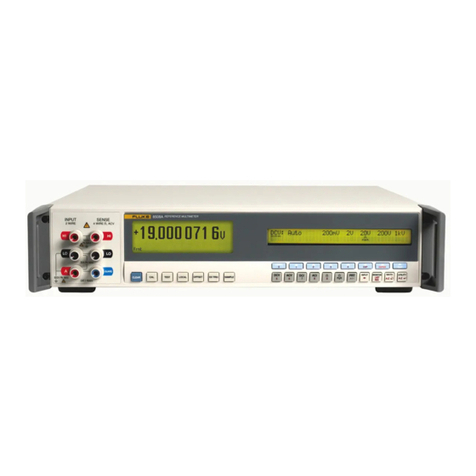
Fluke 8508A User manual

®
8508A
Reference Multimeter
Service Manual
September 2004 Rev. 1, 8/08
© 2004, 2008 Fluke Corporation, All rights reserved. Specifications are subject to change without notice
All product names are trademarks of their respective companies.

Warranty
Each Fluke product is warranted to be free from defects in material and workmanship under normal use and
service. The warranty period is one year and begins on the date of shipment. Parts, product repairs, and
services are warranted for 90 days. This warranty extends only to the original buyer or end-user customer of
a Fluke authorized reseller, and does not apply to fuses, disposable batteries, or to any product which, in
Fluke's opinion, has been misused, altered, neglected, contaminated, or damaged by accident or abnormal
conditions of operation or handling. Fluke warrants that software will operate substantially in accordance
with its functional specifications for 90 days and that it has been properly recorded on non-defective media.
Fluke does not warrant that software will be error free or operate without interruption.
Fluke authorized resellers shall extend this warranty on new and unused products to end-user customers
only but have no authority to extend a greater or different warranty on behalf of Fluke. Warranty support is
available only if product is purchased through a Fluke authorized sales outlet or Buyer has paid the
applicable international price. Fluke reserves the right to invoice Buyer for importation costs of
repair/replacement parts when product purchased in one country is submitted for repair in another country.
Fluke's warranty obligation is limited, at Fluke's option, to refund of the purchase price, free of charge repair,
or replacement of a defective product which is returned to a Fluke authorized service center within the
warranty period.
To obtain warranty service, contact your nearest Fluke authorized service center to obtain return
authorization information, then send the product to that service center, with a description of the difficulty,
postage and insurance prepaid (FOB Destination). Fluke assumes no risk for damage in transit. Following
warranty repair, the product will be returned to Buyer, transportation prepaid (FOB Destination). If Fluke
determines that failure was caused by neglect, misuse, contamination, alteration, accident, or abnormal
condition of operation or handling, including overvoltage failures caused by use outside the product’s
specified rating, or normal wear and tear of mechanical components, Fluke will provide an estimate of repair
costs and obtain authorization before commencing the work. Following repair, the product will be returned to
the Buyer transportation prepaid and the Buyer will be billed for the repair and return transportation charges
(FOB Shipping Point).
THIS WARRANTY IS BUYER'S SOLE AND EXCLUSIVE REMEDY AND IS IN LIEU OF ALL OTHER
WARRANTIES, EXPRESS OR IMPLIED, INCLUDING BUT NOT LIMITED TO ANY IMPLIED WARRANTY
OF MERCHANTABILITY OR FITNESS FOR A PARTICULAR PURPOSE. FLUKE SHALL NOT BE LIABLE
FOR ANY SPECIAL, INDIRECT, INCIDENTAL, OR CONSEQUENTIAL DAMAGES OR LOSSES,
INCLUDING LOSS OF DATA, ARISING FROM ANY CAUSE OR THEORY.
Since some countries or states do not allow limitation of the term of an implied warranty, or exclusion or
limitation of incidental or consequential damages, the limitations and exclusions of this warranty may not
apply to every buyer. If any provision of this Warranty is held invalid or unenforceable by a court or other
decision-maker of competent jurisdiction, such holding will not affect the validity or enforceability of any other
provision.
Fluke Corporation
P.O. Box 9090
Everett, WA 98206-9090
U.S.A.
Fluke Europe B.V.
P.O. Box 1186
5602 BD Eindhoven
The Netherlands
11/99
To register your product online, visit register.fluke.com

i
Table of Contents
Chapter Title Page
1 Introduction and Specifications......................................................... 1-1
Introduction........................................................................................................ 1-3
Safety Considerations ........................................................................................ 1-3
Symbols ......................................................................................................... 1-5
Service Information ........................................................................................... 1-6
How to Contact fluke......................................................................................... 1-6
Specifications..................................................................................................... 1-6
General Specifications................................................................................... 1-7
Maximum Voltage and Current Inputs.......................................................... 1-8
DC and AC Voltage .................................................................................. 1-8
DC and AC Current................................................................................... 1-8
Resistance and Temperature ..................................................................... 1-8
DC Voltage.................................................................................................... 1-9
DC Current .................................................................................................... 1-10
AC Voltage.................................................................................................... 1-11
AC Current .................................................................................................... 1-13
Resistance...................................................................................................... 1-15
Temperature................................................................................................... 1-17
Read Rate and Additional Uncertainty.......................................................... 1-18
Applying the Specifications............................................................................... 1-19
Introduction ................................................................................................... 1-19
Absolute and Relative Specifications ............................................................ 1-19
Applying User’s Calibration Uncertainties ................................................... 1-20
Operating and Calibration Temperature Ranges ........................................... 1-20
Applying Temperature Coefficient Specifications ........................................ 1-20
Ratio Measurements ...................................................................................... 1-21
Additional Errors ........................................................................................... 1-21
2 Theory of Operation ............................................................................ 2-1
Introduction........................................................................................................ 2-3
Overall Functional Description.......................................................................... 2-3
Main Assemblies ........................................................................................... 2-3
Power Supplies .............................................................................................. 2-6

8508A
Service Manual
ii
3 Calibration and Verification................................................................ 3-1
Introduction........................................................................................................ 3-3
Calibration Overview......................................................................................... 3-3
Calibration Interval and Performance................................................................ 3-3
Calibration Points .............................................................................................. 3-3
Non-Nominal Values..................................................................................... 3-4
Enabling Access to Calibration Mode ............................................................... 3-4
Calibration Menus.............................................................................................. 3-4
Accessing the Calibration Menus and Calibration Mode .............................. 3-4
Calibration Menu........................................................................................... 3-4
SET VALUE Menu ....................................................................................... 3-5
SPOT CAL Menu .......................................................................................... 3-6
SPOT (1 to 6) RMS Menus ........................................................................... 3-6
SPOT FREQUENCY (1 to 6) Menu ............................................................. 3-6
Special Calibration ........................................................................................ 3-7
SPCL Menu ................................................................................................... 3-7
SER # = Menu ............................................................................................... 3-7
Hvlin Menu.................................................................................................... 3-8
Non-volatile input offset compensation............................................................. 3-8
Routine Calibration............................................................................................ 3-9
Equipment Required for Calibration ............................................................. 3-10
Preparing for Calibration............................................................................... 3-10
Interconnections ............................................................................................ 3-11
ADC Calibration............................................................................................ 3-14
DC Voltage Calibration................................................................................. 3-14
AC Voltage Calibration................................................................................. 3-16
Resistance Calibration ................................................................................... 3-18
DC Current Calibration ................................................................................. 3-25
AC Current Calibration ................................................................................. 3-27
Frequency Calibration ................................................................................... 3-28
Exit From Calibration Mode and Non-Volatile Input Offset Adjustment..... 3-29
Cal Due Date Entry and Calibration Mode Disable ...................................... 3-30
ACV Spot Frequency Calibration...................................................................... 3-30
Performance Verification................................................................................... 3-31
Equipment Requirements .............................................................................. 3-32
Interconnections ............................................................................................ 3-32
Applicable Verification Tolerance and Conditions ....................................... 3-32
Preparation..................................................................................................... 3-33
DC Voltage Checks ....................................................................................... 3-33
AC Voltage Checks ....................................................................................... 3-35
Resistance Checks ......................................................................................... 3-37
DC Current Checks........................................................................................ 3-40
AC Current Checks........................................................................................ 3-41
Frequency Checks ......................................................................................... 3-43
4 Maintenance......................................................................................... 4-1
Introduction........................................................................................................ 4-3
Access Procedures ............................................................................................. 4-3
Before You Start............................................................................................ 4-3
Cabling and Wiring Connections .................................................................. 4-4
Removing the A1 DC PCA ........................................................................... 4-5
Removing the A2 AC PCA ........................................................................... 4-6
Removing the A3 Ohms PCA ....................................................................... 4-7
Removing the A4 Digital PCA...................................................................... 4-8

Contents (continued)
iii
Removing the A5 Bezel Assembly................................................................ 4-9
Removing the A5A1 Display PCA................................................................ 4-10
Removing the A6 Rear Input Assembly........................................................ 4-11
Fuse Replacement and Line-Voltage Selection ................................................. 4-12
Line-Power Fuse F1 and Voltage Selection .................................................. 4-12
Rear-Input Current Fuse F2 (Rear Inputs Option)......................................... 4-13
Self Test ............................................................................................................. 4-13
Self-Test Errors ............................................................................................. 4-13
Fatal Errors .................................................................................................... 4-16
Execution Errors............................................................................................ 4-18
Device Dependant Errors .............................................................................. 4-19
5 List of Replaceable Parts.................................................................... 5-1
Introduction........................................................................................................ 5-3
How to Obtain Parts........................................................................................... 5-3
How to Contact Fluke ........................................................................................ 5-3
Parts Lists........................................................................................................... 5-4

8508A
Service Manual
iv

v
List of Tables
Table Title Page
3-1. Required Equipment for Calibration and Performance Verification...................... 3-10
3-2. Calibration Sequence ............................................................................................. 3-11
3-3. DC Voltage Calibration Points and Sequence........................................................ 3-15
3-4. AC Voltage Calibration Points and Sequence........................................................ 3-17
3-5. Resistance Calibration Points and Sequence.......................................................... 3-18
3-6. DC Current Calibration Points and Sequence ........................................................ 3-26
3-7. AC Current Calibration Points and Sequence ........................................................ 3-28
3-8. DC Voltage Verification Points and Sequence ...................................................... 3-34
3-9. AC Voltage Verification Points and Sequence ...................................................... 3-36
3-10. Resistance Verification Points and Sequence ........................................................ 3-39
3-11. DC Current Verification Points and Sequence....................................................... 3-41
3-12. AC Current Verification Points and Sequence....................................................... 3-42
4-1. Power Input Fuse 1................................................................................................. 4-12
4-2. Current Function Rear Input Fuse 2....................................................................... 4-13
4-3. Self-Test Errors ...................................................................................................... 4-13
4-4. 9000 System Kernel Fault Errors........................................................................... 4-16
4-5. Unexpected Exception Errors................................................................................. 4-16
4-6. Serial Interface Errors ............................................................................................ 4-17
4-7. Serial Loop Mismatch Errors ................................................................................. 4-18
4-8. Execution Errors..................................................................................................... 4-19
4-9. Device Dependent Errors ....................................................................................... 4-20
5-1. 8508A Final Assembly........................................................................................... 5-4
5-2. 8508A Chassis Assembly....................................................................................... 5-6
5-2. Bezel (front panel) Assembly................................................................................. 5-7
5-4. A6Rear Input Assembly (optional) ........................................................................ 5-12

8508A
Service Manual
vi

vii
List of Figures
Figure Title Page
1-1. 8508A Dimentional Outline Drawing .................................................................... 1-6
2-1. 8508A Functional Block Diagram ......................................................................... 2-4
2-2. Power Supplies - Simplified Block Diagram ......................................................... 2-7
3-1. Equipment Connections Required for Calibration ................................................. 3-13
4-1. Internal Wiring and Cabling Diagram.................................................................... 4-4
4-3. Removing the A2 AC PCA .................................................................................... 4-6
4-4. Removing the A3 Ohms PCA ................................................................................ 4-7
4-5. Removing the A4 Digital PCA............................................................................... 4-8
4-6. Removing the A5 Bezel Assembly ........................................................................ 4-9
4-7. Removing the A5A1 Display PCA ........................................................................ 4-10
4-8. Removing the A6 Rear Input Assembly ................................................................ 4-11
4-9. Rear Panel - Power Input Fuse and line Power Locations ..................................... 4-12
5-1. 8508A Final Assembly........................................................................................... 5-5
5-2. 8508A Chassis Assembly....................................................................................... 5-7
5-3. A5 Bezel (front panel) Assembly........................................................................... 5-11
5-4. Rear Input Assembly (optional) ............................................................................. 5-14

8508A
Service Manual
viii

1-1
Chapter 1
Introduction and Specifications
Title Page
Introduction.......................................................................................................... 1-3
Safety Considerations .......................................................................................... 1-3
Symbols ........................................................................................................... 1-5
Service Information ............................................................................................. 1-6
How to Contact fluke........................................................................................... 1-6
Specifications....................................................................................................... 1-6
General Specifications..................................................................................... 1-7
Maximum Voltage and Current Inputs............................................................ 1-8
DC and AC Voltage .................................................................................... 1-8
DC and AC Current..................................................................................... 1-8
Resistance and Temperature ....................................................................... 1-8
DC Voltage...................................................................................................... 1-9
DC Current ...................................................................................................... 1-10
AC Voltage...................................................................................................... 1-11
AC Current ...................................................................................................... 1-13
Resistance........................................................................................................ 1-15
Temperature..................................................................................................... 1-17
Read Rate and Additional Uncertainty............................................................ 1-18
Applying the Specifications................................................................................. 1-19
Introduction ..................................................................................................... 1-19
Absolute and Relative Specifications .............................................................. 1-19
Applying User’s Calibration Uncertainties ..................................................... 1-20
Operating and Calibration Temperature Ranges ............................................. 1-20
Applying Temperature Coefficient Specifications .......................................... 1-20
Ratio Measurements ........................................................................................ 1-21
Additional Errors ............................................................................................. 1-21

8508A
Service Manual
1-2

Introduction and Specifications
Introduction 1
1-3
Introduction
The Fluke 8508A Reference Multimeter (hereafter "the Multimeter") is designed for the
most demanding measurement applications and provides extremely high measurement
precision in both stand-alone and systems applications.
This Service Manual provides the information necessary to maintain the Multimeter at a
module (or board) level. A brief description of the information contained in the various
chapters follows:
Chapter 1 Introduction and Specification provides a brief description of the product,
safety information regarding the product and its use, and a complete set of detailed
specifications.
Chapter 2 Theory of Operation provides an overall functional description of the internal
workings of the Multimeter. The intent of the theory is to aid in locating and isolating a
faulty PCA.
Chapter 3 Calibration and Verification provides a thorough and complete description of
both the Verification and the Calibration procedures for the Multimeter.
Chapter 4 Maintenance provides detailed descriptions of how to disassemble the
Multimeter to the PCA level. The purpose of the descriptions is to assist with equipment
repairs at the PCA level.
Chapter 5 List of Replaceable Parts provides all of the information required to identify
and order replacement parts for repairing the Multimenter at the PCA level.
XW Warning
To avoid electric shock, personal injury, or death, carefully read
the information under Safety Considerations before attempting
to install, use, or service the Multimeter.
Safety Considerations
This instrument has been designed and tested in accordance with the European standard
publication EN61010-1: 2001 and U.S. / Canadian standard publications UL 61010-1A1
and CAN/CSA-C22.2 No.61010.1. The instrument has been supplied in a safe condition.
This manual contains information and warnings that must be observed to keep the
instrument in a safe condition and ensure safe operation.
Using or servicing this Multimeter in conditions other than as specified in the Service
Manual could compromise your safety.
To use the Multimeter correctly and safely, read and adhere to the precautions on the
Safety Page and follow all the safety instructions or warnings given throughout this
manual and the Users Manual that relate to specific measurement functions. In addition,
follow all generally accepted safety practices and procedures required when working with
and around electricity.

8508A
Service Manual
1-4
XW Safety – Read First
Warning: To avoid possible electric shock, personal injury, or death, read the following
before using the Multimeter:
⇒Use the Multimeter only as specified in this manual, or the protection provided by
the Multimeter might be impaired.
⇒Do not use the Multimeter in wet environments.
⇒The Multimer can output lethal voltages. Use it only as described in this manual.
⇒Inspect the Multimeter before using it. Do not use the Multimeter if it appears
damaged. Pay particular attention to the insulation around the connectors.
⇒Inspect the test leads before use. Do not use them if insulation is damaged or metal
is exposed. Check the test leads for continuity. Replace damaged test leads before
using the Multimeter.
⇒Verify the Multimeter's operation by measuring a known voltage before and after
using it. Do not use the Multimeter if it operates abnormally. Protection may be
impaired. If in doubt, have the Multimeter serviced.
⇒Whenever it is likely that safety protection has been impaired, make the Multimeter
inoperative and secure it against any unintended operation.
⇒Have the Multimeter serviced only by qualified service personnel.
⇒Do not apply more than the rated voltage, as marked on the Multimeter, between
the terminals or between any terminal and earth ground.
⇒Always use the power cord and connector appropriate for the voltage and outlet of
the country or location in which you are working.
⇒Remove test leads from the Multimeter before opening the case.
⇒Never remove the cover or open the case of an instrument without first removing
the power source.
⇒Never operate the Multimeter with the cover removed or the case open.
⇒Use caution when working with voltages above 30 V ac rms, 42 V ac peak, or 42 V
dc. These voltages pose a shock hazard.
⇒Use only the replacement fuse(s) specified by the manual.
⇒Use the proper terminals, function, and range for your measurements.
⇒Do not operate the Multimeter around explosive gas, vapor, or dust.
⇒When using probes, keep your fingers behind the finger guards.
⇒When making electrical connections, connect the common test lead before
connecting the live test lead; when disconnecting, disconnect the live test lead
before disconnecting the common test lead.
⇒Disconnect circuit power and discharge all high-voltage capacitors before testing
resistance, continuity, diodes, or capacitance.
⇒Before measuring current, check the Multimeter's fuses and turn OFF power to the
circuit before connecting the Multimeter to the circuit.
⇒When servicing the Multimeter, use only specified replacement parts.

Introduction and Specifications
Safety Considerations 1
1-5
Symbols
The following safety and electrical symbols may be used on the Multimeter or in this
manual.
WRisk of danger.
Important information. See manual. +Power ON / OFF
XHazardous voltage. Voltage > 30 V dc or
ac peak might be present JEarth ground.
BAC (Alternating Current). CAT IEC 61010 Overvoltage (installation or
measurement) Category .
FDC (Direct Current). IFuse.
D
or
CAC or DC (Alternating or Direct Current) ~Do not dispose of this product as unsorted
municipal waste. Go to Fluke’s website for
recycling information.
HDigital signal. <Recycle.
YPotentially hazardous voltage. TDouble insulated.

8508A
Service Manual
1-6
Service Information
In case of difficulty within the 1-year Warranty period, return the Multimeter to a Fluke
Service Center for Warranty repair. For out of Warranty repair, contact a Fluke Service
Center for a cost estimate.
This service manual provides instructions for verification of performance, calibration,
and maintenance. If you choose to repair a malfunction, information in this manual can
help you to determine which module (PCA) has a fault. See Chapter 5 for cautions about
handling the internal components.
How to Contact fluke
To contact Fluke, call one of the following telephone numbers:
USA: 1-888-99-FLUKE (1-888-993-5853)
Canada: 1-800-36-FLUKE (1-800-363-5853)
Europe: +31 402-675-200
Japan: +81-3-3434-0181
Singapore: +65-738-5655
Anywhere in the world: +1-425-446-5500
Or, visit Fluke's Web site at www.fluke.com.
To register your product, visit register.fluke.com
Specifications
Figure 1-1 shows the overall dimensions of the 8505A Reference Multimeter.
8.8 mm
(3.5 in)
427 mm
(16.8 in)
487 mm
(19.2 in)
avw001f.eps
Figure 1-1. 8508A Dimentional Outline Drawing

Introduction and Specifications
Specifications 1
1-7
General Specifications
Power
Voltage
115 V Setting ..................................................... 100 V to 120 V rms ±10 %
230 V Setting ..................................................... 200 V to 240 V rms ±10 %
Frequency ............................................................... 47 Hz to 63 Hz
Consumption........................................................... < 80 VA
Dimensions
Height...................................................................... 88 mm (3.5 inches)
Width....................................................................... 427 mm (16.8 inches)
Depth ...................................................................... 487 mm (19.2 inches)
Weight..................................................................... 11.5 kg (25.5 lbs)
Environment
Temperature
Operating............................................................ 0 °C to 50 °C
Specified Operation ............................................ 5 °C to 40 °C
Calibration (TCal)................................................ 20 °C to 25 °C
Factory Cal Temp ............................................... 23 °C
Storage ............................................................... -20 °C to 70 °C
Warm Up............................................................. 4 hours to full uncertainty specification.
Relative Humidity (non- condensing)
Operating ........................................................... 5 °C to 40 °C < 90 %
Storage .............................................................. 0 °C to 70 °C < 95 %
Altitude
Operating............................................................ < 2000 meters
Storage ............................................................... < 12000 meters
Vibration and Shock................................................ Complies with MIL-PRF-28800F Class 3.
Safety ..................................................................... Designed and tested to EN61010-1: 2001, UL 61010-1A1,
CAN/CSA-C22.2 No.61010.1, CE and ETL marked.
Pollution Degree 2.
Installation Category II.
Equipment Class I (single insulation / Earthed metal case).
Protection against water ingress IP4X (general indoor conditions).
Input circuitry and connections (creepage and clearances) designed to
interface at Installation or Measurement Category I.
EMC ........................................................................ EN50081-1 Class B, EN55011/22, EN61326-1:1998,
EN50082-1, EN55011 1991 Class B,
EN61000-6-1:2001, FCC Rules part 15 sub part J class B,
CETL and CE marked.
Measurement Isolation
Guard to Safety Ground ......................................... < 3300 pF, > 10 GΩ.
Lo to Guard
In Remote Guard ................................................ < 2800 pF, > 10 GΩ(Not in Resistance function).
In Local Guard .................................................... Lo and Guard terminals are internally shorted
(in Resistance < 2800 pF, > 10 GΩ).
Autorange
Range Up................................................................ 100 % of range.
Range Down ........................................................... 9 % of range (18 % on 1000 V range).
Remote Interface................................................... IEEE 488.2
Warranty ................................................................ 1 Year

8508A
Service Manual
1-8
Maximum Voltage and Current Inputs
Notes to maximum voltage and current input specifications
•Maximum DC input equal to maximum rms input. Maximum peak input is rms x 1.414
•Specifications apply equally to front and rear input terminals except where noted below.
•Front to rear isolation allows opposing polarity of maximum terminal voltage on each input.
•Digital I/O Ground (DigGnd) is internally connected to Safety Ground (Ground).
DC and AC Voltage
Maximum rms terminal voltages
Sense Hi
Hi 250 V
Sense Lo 1000 V 1000 V
Lo 250 V 1000 V 1000 V
A 1000 V 1000 V 1000 V 1000 V
Guard 1000 V 250 V 250 V 1000 V 1000 V
DigGnd 650 V 650 V 650 V 650 V 1000 V 1000 V
Ground 0 V 650 V 650 V 650 V 650 V 1000 V 1000 V
Notes
•The A terminal is open circuit in these functions.
•In 4wV mode Sense Hi is internally connected to Hi and Sense Lo is internally connected to Lo.
DC and AC Current
Maximum rms terminal voltages
Sense Hi
Hi 250 V
Sense Lo 1000 V 1000 V
Lo 250 V 1000 V 1000 V
A 5 V 250 V 1000 V 1000 V
Guard 250 V 250 V 250 V 1000 V 1000 V
DigGnd 650 V 650 V 650 V 650 V 1000 V 1000 V
Ground 0 V 650 V 650 V 650 V 650 V 1000 V 1000 V
Maximum rms terminal currents
Guard A Lo Sense Lo Hi Sense Hi
Front Input n.a 20 A 20 A n.a n.a n.a
Rear input n.a 2 A 2 A n.a n.a n.a
Notes
•The Sense Lo, Sense Hi, and Hi Terminals are open circuit in these functions.
•The front input A terminal protection is automatic and self-resetting, and does not interrupt current flow. Damage is likely to
occur if more than 20 A is applied.
•The rear input A terminal is protected by a fuse mounted on the rear panel.
Resistance and Temperature
Maximum rms terminal voltages
Sense Hi
Hi 250 V
Sense Lo 250 V 250 V
Lo 250 V 250 V 250 V
A 250 V 250 V 250 V 250 V
Guard 250 V 250 V 250 V 250 V 250 V
DigGnd 650 V 650 V 650 V 650 V 1000 V 1000 V
Ground 0 V 650 V 650 V 650 V 650 V 1000 V 1000 V
Note
•The A terminal is open circuit in these functions.

Introduction and Specifications
Specifications 1
1-9
DC Voltage
DC Voltage [1] [2] [3]
Uncertainty Relative to Cal Stds Absolute Uncertainties
± (ppm Reading + ppm Range)[4]
Range Full Scale[15] 24 hour
TCal ±1 °C 90 day
TCal ±1 °C 365 day
TCal ±1 °C 365 day
TCal ±1 °C 365 day TCal
±5 °C
95 % Confidence Level
200 mV 199.990 000 0.7 + 0.5 1.4 + 0.5 2.7 + 0.5 4.5 + 0.5 5.0 + 0.5
2 V 1.999 900 00 0.5 + 0.2 1.4 + 0.2 2.7 + 0.2 3.0 + 0.2 3.5 + 0.2
20 V 19.999 000 0 0.5 + 0.2 1.4 + 0.2 2.7 + 0.2 3.0 + 0.2 3.5 + 0.2
200 V 199.990 000 1.0 + 0.2 2.6 + 0.2 4.0 + 0.2 4.5 + 0.2 5.5 + 0.2
1000 V 1050.000 00 1.0 + 0.5 2.6 + 0.5 4.0 + 0.5 4.5 + 0.5 5.5 + 0.5
99 % Confidence Level
200 mV 199.990 000 0.8 + 0.6 2.0 + 0.6 3.5 + 0.6 6.0 + 0.6 6.5 + 0.6
2 V 1.999 900 00 0.6 + 0.25 1.8 + 0.25 3.5 + 0.25 4.0 + 0.25 4.5 + 0.25
20 V 19.999 000 0 0.6 + 0.25 1.8 + 0.25 3.5 + 0.25 4.0 + 0.25 4.5 + 0.25
200 V 199.990 000 1.2 + 0.25 3.5 + 0.25 5.2 + 0.25 6.0 + 0.25 7.0 + 0.25
1000 V 1050.000 00 1.2 + 0.6 3.5 + 0.6 5.2 + 0.6 6.0 + 0.6 7.0 + 0.6
DC Voltage (Secondary Specifications)[1] [2] [3]
Temperature Coefficient
15 °C - 30 °C 5 °C - 15 °C
30 °C - 40 °C
Range
Transfer Uncertainty
20 mins ±1 °C ± (ppm
Reading+ ppm Range) ± ppm Reading/°C
200 mV 0.4 + 0.3 0.4 0.6
2 V 0.12 + 0.1 0.3 0.5
20 V 0.12 + 0.1 0.3 0.5
200 V 0.4 + 0.1 0.7 1.0
1000 V 0.4 + 0.3 0.7 1.0
Type ....................................................................... Multi-slope, multi-cycle A-D Converter
CMRR (1 kΩunbalance) [5] .................................... 140 dB at DC and 1 - 60 Hz
NMRR [5]
Filter Out ................................................................. 60 dB at 50/60 Hz ±0.09 %
Filter In .................................................................... 110 dB at 50/60 Hz ±0.09 %
Protection (All ranges)........................................... 1 kV rms
Input Impedance
200 mV to 20 V Ranges.......................................... > 10 GΩ
200 V & 1000 V Ranges ......................................... 10.1 MΩ± 1 %
Max Input Current ................................................. 50 pA
Ratio Accuracy
Range to Range...................................................... ±(Net Front Input Accuracy + Net Rear Input Accuracy)
Within Range .......................................................... Apply 24 hour or 20 minute Transfer Uncertainty specifications
Settling Time (to 10 ppm step size)
Filter Out ................................................................. < 50 ms
Filter In .................................................................... < 1 s

8508A
Service Manual
1-10
DC Current
DC Current [1] [2] [3]
Uncertainty Relative to Cal Stds Absolute Uncertainties
± (ppm Reading + ppm Range)[4]
Range Full Scale[15] 24 hour
TCal ±1 °C 90 day
TCal ±1 °C 365 day
TCal ±1 °C 365 day
TCal ±1 °C 365 day
TCal ±5 °C
95 % Confidence Level
200 μA 199.990 00 5.5 + 2.0 6.0 + 2.0 6.5 + 2.0 12 + 2.0 12 + 2.0
2 mA 1.999 900 0 5.5 + 2.0 6.0 + 2.0 6.5 + 2.0 12 + 2.0 12 + 2.0
20 mA 19.999 000 6.5 + 2.0 7.0 + 2.0 8.0 + 2.0 13 + 2.0 14 + 2.0
200 mA 199.990 00 28 + 4.0 30 + 4.0 33 + 4.0 36 + 4.0 48 + 4.0
2 A 1.999 900 0 80 + 8.0 125 + 8.0 170 + 8.0 170 + 8.0 185 + 8.0
20 A 19.999 000 200 + 20 290 + 20 380 + 20 380 + 20 400 + 20
99 % Confidence Level
200 μA 199.990 00 7.0 + 2.0 7.5 + 2.0 8.0 + 2.0 15 + 2.0 16 + 2.0
2 mA 1.999 900 0 7.0 + 2.0 7.5 + 2.0 8.0 + 2.0 15 + 2.0 16 + 2.0
20 mA 19.999 000 8.0 + 2.0 9.0 + 2.0 10 + 2.0 16 + 2.0 18 + 2.0
200 mA 199.990 00 35 + 4.0 37 + 4.0 40 + 4.0 45 + 4.0 60 + 4.0
2 A 1.999 900 0 100 + 8.0 150 + 8.0 205 + 8.0 210 + 8.0 225 + 8.0
20 A 19.999 000 250 + 20 350 + 20 450 + 20 455 + 20 500 + 20
DC Current (Secondary Specifications) [1] [2] [3]
Temperature Coefficient
Input Impedance (Ω) 15 °C - 30 °C 5 °C - 15 °C
30 °C - 40 °C
Range
Front Rear ± ppm Reading/°C
200 μA 150 150 0.4 0.6
2 mA 15.2 15.2 0.4 0.6
20 mA 1.8 1.9 1.2 1.8
200 mA 1.2 1.3 6. 0 9.0
2 A 0.3 0.4 8.0 12
20 A 0.04 -15 20
Type........................................................................ Multi-slope, multi-cycle A-D Converter
Protection
Front Input............................................................... 20 A rms
Rear Input ............................................................... 2 A rms, Rear Panel Fuse
Settling Time
200 μA to 200 mA Ranges, to 10 ppm step size .... Filter Out < 50 ms, Filter In < 1 s
2 A Range
to 100 ppm step size........................................... < 1 s
to 75 ppm step size............................................. < 30 s
to 30 ppm step size............................................. < 5 minutes
20 A Range (at 10 A)
to 300 ppm step size........................................... < 1 s
to 250 ppm step size........................................... < 30 s
to 100 ppm step size........................................... < 5 minutes
Other manuals for 8508A
3
Table of contents
Other Fluke Multimeter manuals

Fluke
Fluke III Series User manual

Fluke
Fluke 10 User manual

Fluke
Fluke 79 III Use and care manual

Fluke
Fluke 75 User manual

Fluke
Fluke 114 Use and care manual

Fluke
Fluke 8010A User manual

Fluke
Fluke 77 User manual

Fluke
Fluke 233 Parts list manual

Fluke
Fluke 8060A User manual

Fluke
Fluke 8845A Use and care manual