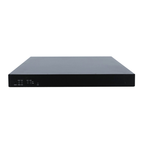
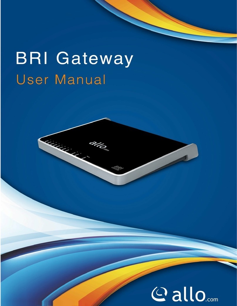
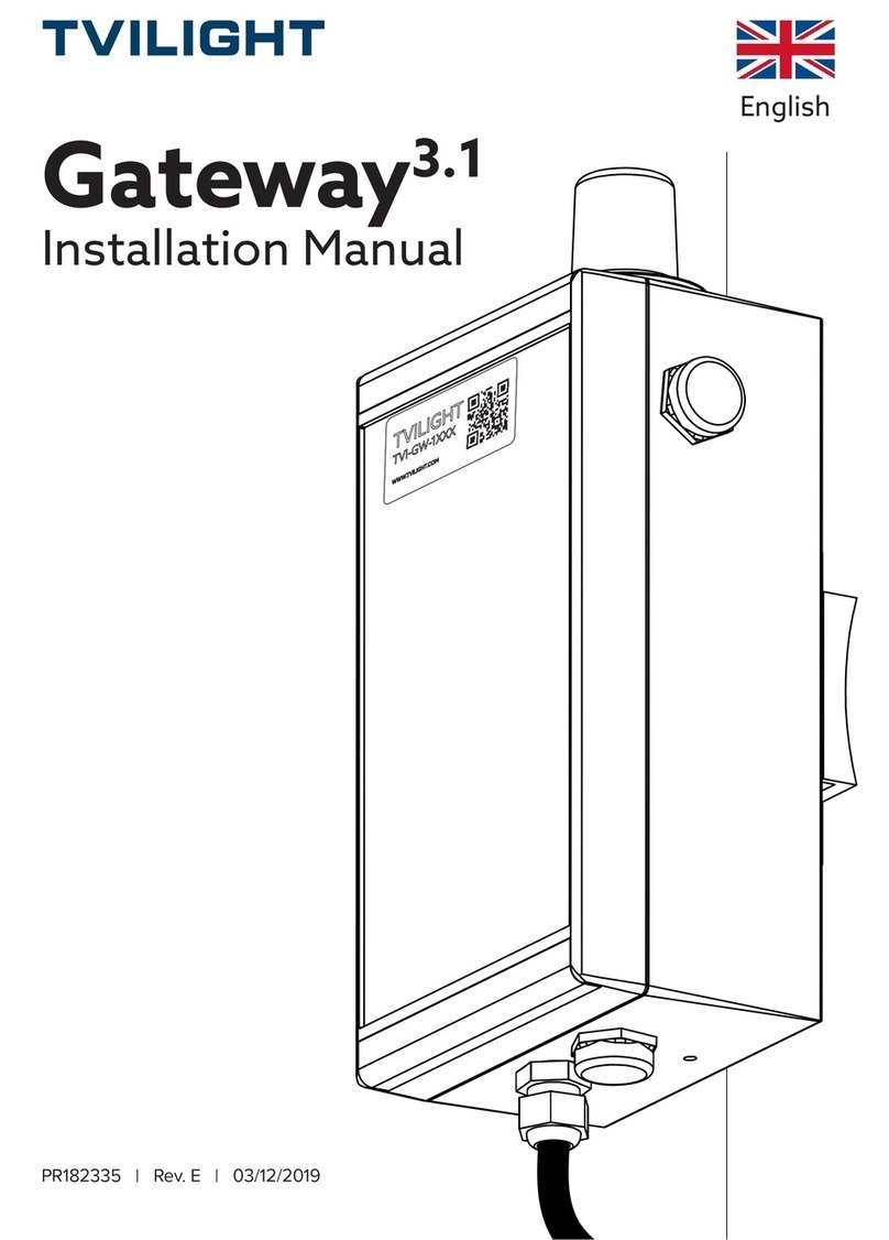
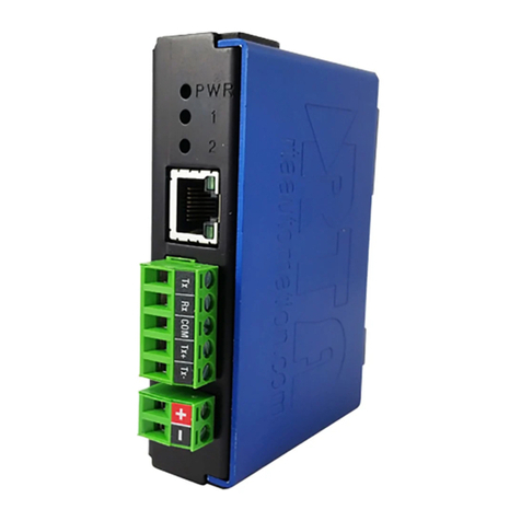
Adec A-dec+ 43.0531.00 User manual

A-dec+™Gateway
INSTALLATION GUIDE
86.0924.00 Rev B
Product Models and Versions Covered in This Document
Models Versions Description
43.0531.00 n/a Gateway Network Device
Contents
Before You Begin . . . . . . . . . . 2
Install the A-dec+ Gateway . . 2
Connect to A-dec+ . . . . . . . . 11
Regulatory Information and
Warranty . . . . . . . . . . . . . . . . 12

A-dec+ Gateway Installation Guide
286.0924.00 Rev B
Before You Begin
Recommended Tools
•Hexkeyset
Install the A-dec+ Gateway
For all A-dec systems, except the 500 Pro delivery systems, you must install the A-dec+ Gateway to use the
A-dec+ system. The A-dec+ Gateway can be placed in a chair floorbox or in a cabinet near the chair. Wired
Ethernet is the preferred connection method over Wi-Fi, if possible.
Follow the appropriate procedure for your installation.
Install the Gateway in a Floorbox . . . . . . . . . 2
Install the Gateway in a Cabinet . . . . . . . 10
Install the Gateway in a Floorbox
1. Turn off the power to the system.
2. Remove the floorbox cover.
3. Remove the pump cover.
4. Place the Gateway in the floorbox.
WARNING Failure to turn off or disconnect the power before you begin this procedure can lead to product
damage and result in serious injury or death.
WARNING Shock hazard. When you remove or replace the covers, take care not to damage any wiring or
tubing. Verify that the covers are secure after you replace them.
ATTENTION Circuit boards are sensitive to static electricity. Electrostatic Discharge (ESD) precautions are
required when touching a circuit board or making connections to or from the circuit board. Circuit
boards should be installed only by an electrician or qualified service person.

A-dec+ Gateway Installation Guide
86.0924.00 Rev B 3
Connect the Electrical Wires and Data Line
Complete the following section according to which power supply the system includes.
A-dec Universal Power Supply Manufactured
After June 2023 . . . . . . . . . . . . . . . . . . . . . . . . . . . . . 4
A-dec 511 Power Supply Manufactured Before
June 2023 . . . . . . . . . . . . . . . . . . . . . . . . . . . . . . . . . . 8
A-dec 311B/411 Power Supply Manufactured
Before June 2023 . . . . . . . . . . . . . . . . . . . . . . . . . . . 6

A-dec+ Gateway Installation Guide
486.0924.00 Rev B
A-dec Universal Power Supply Manufactured After June 2023
You can power the Gateway using the chair circuit board or the external power supply. Complete one of the
following procedures based on how the Gateway will be powered.
Power the Gateway Using the Chair Circuit Board . . . . . . . . . 4
Power the Gateway Using the External Power Supply . . . . . . 5
Power the Gateway Using the Chair Circuit Board
1. Plug the black with white stripe wire of the pigtail power cable into the 0 V connector.
2. Plug the black wire of the pigtail power cable into the 24 V connector.
3. Plug the pigtail connector into the Gateway.
4. Plug one end of the red DCS2 data line into a DCS2 data port on the chair circuit board.
5. Plug the other end of the red DCS2 data line into the DCS2 port on Gateway.
6. If you will use Ethernet instead of Wi-Fi for the network connection:
(1) Connect one end of the Ethernet cable to the Gateway.
(2) Connect the other end of the Ethernet cable to a router.
Next Step See “Connect to A-dec+” on page 11.
Pigtail
A-dec 511 Shown
12
3
4
5
6
24 V
0 V
3
5
DCS2 Data Line
Ethernet Cable

A-dec+ Gateway Installation Guide
86.0924.00 Rev B 5
Power the Gateway Using the External Power Supply
1. Plug the external power supply into an outlet.
2. Plug the external power supply cable into the Gateway.
3. Plug one end of the red DCS2 data line into a DCS2 data port on the chair circuit board.
4. Plug the other end of the red DCS2 data line into the DCS2 port Gateway.
5. If you will use Ethernet instead of Wi-Fi for the network connection:
(1) Connect one end of the Ethernet cable to the Gateway.
(2) Connect the other end of the Ethernet cable to a router.
WARNING Fire hazard. Use only the external power supply provided with the Gateway. Using another
external power supply might result in a fire hazard. Another power supply might also result in an
inability to meet conducted emissions standards.
Next Step See “Connect to A-dec+” on page 11.
A-dec 511 Shown
1
3
2
4
5
2
4
Ethernet Cable
DCS2 Data Line

A-dec+ Gateway Installation Guide
686.0924.00 Rev B
A-dec 311B/411 Power Supply Manufactured Before June 2023
You can power the Gateway using the chair circuit board or the external power supply. Complete one of the
following procedures based on how the Gateway will be powered.
Power the Gateway Using the Chair Circuit Board . . . . . . . . . 6
Power the Gateway Using the External Power Supply . . . . . . 7
Power the Gateway Using the Chair Circuit Board
1. Plug the black with white stripe wire of the pigtail power cable into the 0V connector.
2. Plug the black wire of the pigtail power cable into the 24V connector.
3. Plug the pigtail connector into the Gateway.
4. Plug one end of the DCS1 data line into a DCS1 data port on the chair circuit board.
5. Plug the other end of the DCS1 data line into the DCS1 port on the Gateway.
6. If you will use Ethernet instead of Wi-Fi for the network connection:
(1) Connect one end of the Ethernet cable to the Gateway.
(2) Connect the other end of the Ethernet cable to a router.
Next Step See “Connect to A-dec+” on page 11.
Pigtail
12
3
4
5
6
24 V
0 V
3
5
DCS1 Data Line
Ethernet Cable
A-dec 311 Shown

A-dec+ Gateway Installation Guide
86.0924.00 Rev B 7
Power the Gateway Using the External Power Supply
1. Plug the external power supply into an outlet.
2. Plug the external power supply cable into the Gateway.
3. Plug one end of the black DCS1 data line into a DCS1 data port on the chair circuit board.
4. Plug the other end of the black DCS1 data line into the DCS1 port on the Gateway.
5. If you will use Ethernet instead of Wi-Fi for the network connection:
(1) Connect one end of the Ethernet cable to the Gateway.
(2) Connect the other end of the Ethernet cable to a router.
WARNING Fire hazard. Use only the external power supply provided with the Gateway. Using another
external power supply might result in a fire hazard. Another power supply might also result in an
inability to meet conducted emissions standards.
Next Step See “Connect to A-dec+” on page 11.
1
3
2
4
5
DCS1 Data Line
Ethernet Cable
2
4
A-dec 311 Shown

A-dec+ Gateway Installation Guide
886.0924.00 Rev B
A-dec 511 Power Supply Manufactured Before June 2023
You can power the Gateway using the chair circuit board or the external power supply. Complete one of the
following procedures based on how the Gateway will be powered.
Power the Gateway Using the Chair Circuit Board . . . . . . . . . 8
Power the Gateway Using the External Power Supply . . . . . . 9
Power the Gateway Using the Chair Circuit Board
1. Remove the existing wires from the J2 connector.
2. Twist the pigtail wires onto the wires removed from J2.
(1) Wrap the pigtail black with white stripe wire around the black wire from J2. Wrap the pigtail black wire
around the gray wire from J2.
(2) Insert the wires back into the original terminals. Insert original black wire into the J1 0 V position, and the
original gray wire into the J2 24 V position.
3. Plug the pigtail connector into the Gateway.
4. Plug one end of the DCS1 data line into a DCS1 data port on the chair circuit board.
5. Plug the other end of the DCS1 data line into the Gateway.
6. If you will use Ethernet instead of Wi-Fi for the network connection:
(1) Connect one end of the Ethernet cable to the Gateway.
(2) Connect the other end of the Ethernet cable to a router.
Next Step See “Connect to A-dec+” on page 11.
1
2
3
456
3
5
DCS1 Data Line
Ethernet Cable
J2 Connector
Pigtail

A-dec+ Gateway Installation Guide
86.0924.00 Rev B 9
Power the Gateway Using the External Power Supply
1. Plug the external power supply into an outlet.
2. Plug the external power supply cable into the Gateway.
3. Plug one end of the DCS1 data line into a data port on the chair circuit board.
4. Plug the other end of the DCS1 data line into the DCS1 data port on the Gateway.
5. If you will use Ethernet instead of Wi-Fi for the network connection:
(1) Connect one end of the Ethernet cable to the Gateway.
(2) Connect the other end of the Ethernet cable to a router.
WARNING Fire hazard. Use only the external power supply provided with the Gateway. Using another
external power supply might result in a fire hazard. Another power supply might also result in an
inability to meet conducted emissions standards.
Next Step See “Connect to A-dec+” on page 11.
A-dec 511 Shown
1
3
2
45
4
2
DCS1 Data Line
Ethernet Cable

A-dec+ Gateway Installation Guide
10 86.0924.00 Rev B
Install the Gateway in a Cabinet
1. Place the Gateway in the cabinet.
2. Route a data line from the Gateway to the chair circuit board:
(1) For a chair power supply manufactured after June 2023 (see the illustrations on page 3), route a red DCS2
data line from the Gateway in the cabinet to the chair circuit board.
(2) For a power supply manufactured before June 2023 (see the illustrations on page 3), route a black DCS1
data line from the Gateway in the cabinet to the chair circuit board.
3. Connect the data line to the Gateway:
(1) For a red DCS2 data line: Plug the end of the data line into the DCS2 data port on the Gateway.
(2) For a black DCS1 data line: Plug the end of the data line into the DCS1 data port on the Gateway.
4. Connect the data line to the chair circuit board:
(1) For a red DCS2 data line: Plug the data line into a DCS2 data port on the chair circuit board (DCS2 data
ports are located on the toe end of the chair circuit board).
(2) For a black DCS1 data line: Plug the data line into a DCS1 data port on the chair circuit board (DCS1 data
ports are located on the head end of the chair circuit board).
5. If you will use Ethernet instead of Wi-Fi for the network connection:
(1) Connect one end of the Ethernet cable to the Gateway.
(2) Connect the other end of the Ethernet cable to a router.
6. Plug the external power supply into an outlet.
NOTE Choose a cabinet that is close to the dental chair.
NOTE Do not locate the Gateway near an antenna or transmitter, such as a Wi-Fi router. Do not place
items directly on top of the Gateway. Allow an air gap around the Gateway for best Wi-Fi performance.
CAUTION Plugging a black DCS1 data line into a DCS2 port can damage the product.
WARNING Fire hazard. Use only the external power supply provided with the Gateway. Using another
external power supply might result in a fire hazard. Another power supply might also result in an
inability to meet conducted emissions standards.

A-dec+ Gateway Installation Guide
86.0924.00 Rev B 11
7. Plug the connector from the external power supply into the Gateway.
Connect to A-dec+
2
3
1
57
6
DCS2 or DCS1
Data Line
Ethernet Cable
For configuring connectivity features, see the
A-dec+™Instructions for Use (p/n 86.1030.00) at
a-dec.com/connectivity-manual.

A-dec+ Gateway Installation Guide
A-dec Headquarters
2601 Crestview Drive
Newberg, OR 97132 USA
Tel: 1.800.547.1883 Within USA/CAN
Tel: +1.503.538.7478 Outside USA/CAN
www.a-dec.com
A-dec, Inc. makes no warranty of any kind with regard to
the content in this document including, but not limited to,
the implied warranties of merchantability and fitness for a
particular purpose.
ÍvÈ.Ç)8È.00jÎ
86.0924.00 Rev B
Date of Issue 2023-05-04
Copyright 2023 A-dec, Inc.
All rights reserved.
IGgrphpor22
Regulatory Information and Warranty
For required regulatory information and the A-dec warranty, see the Regulatory Information, Specifications, and
Warranty document (p/n 86.0221.00) available in the Resource Center at www.a-dec.com.
For quick access to this document online,
scan, tap, or click this QR code, which points
to a-dec.com/regulatory-guide.
All trademarks cited herein are trademarks or registered trademarks of A-dec, Inc. in the United States and may
also be trademarks or registered trademarks in other countries.
Table of contents
