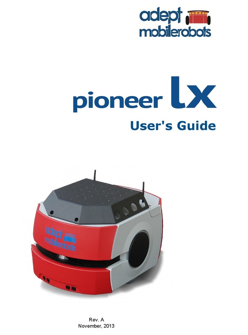
Adept MobileRobots Pioneer 3 User manual

Pioneer 3
Operations Manual
P3DX-SH , P3AT-SH with ARCOS
Mobile Robots for Research an E ucation
P3X0001, P3T0001
Revision 6.4 - October 31, 2013

ii
© 2013 Adept MobileRobots. All rights reserved.
This document, as well as the so tware described in it, is provided under license and may only be used or copied in accordance with
the terms o the respective license.
In ormation in this document is subject to change without notice and should not be construed as a commitment by Adept
MobileRobots.
The so tware on disk, CD-ROM and irmware which accompany the robot and are available or network download by Adept
MobileRobots customers are solely owned and copyrighted or licensed or use and distribution by Adept MobileRobots.
Developers and users are authorized by revocable license to develop and operate custom so tware or personal research and
educational use only. Duplication, distribution, reverse-engineering or commercial application o Adept MobileRobots so tware and
hardware without license or the express written consent o Adept MobileRobots is explicitly orbidden.
Per ormance PeopleBot™, GuiaBot™, AmigoBot™, PowerBot™, PatrolBot®, Seekur®, Seekur® Jr, Mapper3™, MobileSim™ and
MobileEyes™ are trademarks and registered trademarks o Adept MobileRobots. Other names and logos or companies and
products mentioned or eatured in this document are o ten registered trademarks or trademarks o their respective companies.
Mention o any third-party hardware or so tware constitutes neither an endorsement nor a recommendation by Adept MobileRobots.
About Adept MobileRobots
In 1995, ActivMedia, Inc. ventured with Real World Inter ace, Inc. to launch the Pioneer Mobile Robot. In 1999,
ActivMedia, Inc. acquired the rights to Pioneer and spun o ActivMedia Robotics, LLC to better ocus and serve the
mobile robotics research community. In 2006, ActivMedia Robotics, LLC, a New Hampshire limited-liability company,
was dissolved and replaced by MobileRobots Inc, a Delaware corporation. In June o 2010, MobileRobots Inc was
acquired and merged with Adept Technology, Inc. (NASDAQ ADEP), to orm Adept MobileRobots, LLC.
Even though the names have changed, our devotion to provide the best mobile robotics plat orms and so tware has
not.
Pioneer 1
A ept MobileRobots
10 Columbia Dr.
Amherst, NH, USA
03031
(603) 881-7960
http://www.mobilerobots.com

iii
Important Safety Instructions
Read the installation and operations instructions be ore using the equipment.
Avoid using power extension cords.
To prevent ire or shock hazard, do not expose the equipment to rain or moisture.
Re rain rom opening the unit or any o its accessories.
Keep wheels away rom long hair or ur.
Never access the interior o the robot with charger attached or batteries inserted.
Inappropriate Operation
Inappropriate OperationInappropriate Operation
Inappropriate Operation
Inappropriate operation voids your warranty! Inappropriate operation includes, but is not
limited to:
Dropping the robot, running it o a ledge, or otherwise operating it in an irresponsible manner
Overloading the robot above its payload capacity
Getting the robot wet
Continuing to run the robot a ter hair, yarn, string, or any other items have become wound around the robot’s
axles or wheels
Opening the robot with charger attached and/or batteries inserted
All other orms o inappropriate operation or care
Use Adept MobileRobots
authorized parts ONLY
warranty void otherwise.

iv

v
Contents
Chapter 1 Introduction 1
Robot Packages 1
Basic Components (all shipments) 1
Optional Components an Attachments (partial list) 1
User-Supplie Components / System Requirements 2
Additional Resources 2
Support Website 2
Newsgroups 2
Support 3
Chapter 2 What Is Pioneer? 4
Pioneer Reference Platform 4
Pioneer Family of Robot Microcontrollers and Operations Software 4
Software and Pioneer S K 4
Ports and Power 5
Modes of Operation 6
Normal (aka Server) Mo e 6
Maintenance Mo e 6
Chapter 3 Specifications & Controls 7
Physical Characteristics and Components 7
eck 8
E-Stop Button 8
User Control Panel 8
Power an Status In icators 8
Buzzer 8
Serial Port 9
Power Switches 9
Reset an Motors 9
Body, Nose and Accessory Panels 9
Nose 10
Access Panels 10
SONAR 10
Multiplexe Operation 10
Sensitivity A justment 10
Motors, Wheels, and Position Encoders 11
Batteries and Power 11
Battery In icators an Low Voltage Con itions 11
Recharging 11
Safety ARCOS Watchdogs 12
Chapter 4 Accessories 13
Joystick and Joydrive Mode 13
Bumpers 13
Automated Recharging Accessory 14
Manual Operation (Robot Power OFF) 14
Manual Operation (Robot Power an Systems ON) 14
Radio Controls and Accessories 14
Integrated PC 15
Computer Control Panel 15
Operating the Onboar PC 16
Onboar PC Networking 16
Genpower 17
Gyroscope 17
Chapter 5 Quic Start 18
Preparative Hardware Assembly 18
Install Batteries 18
Client-Server Communications 18

vi
emo Client 18
Starting Up ARIA emo 19
Demo Startup Options 19
A Successful Connection 20
Operating the ARIA emonstration Client 20
isconnecting 21
Networking with MobileEyes 21
Start serverDemo 21
Start MobileEyes an Connect with serverDemo 21
Operating MobileEyes 21
Quickstart Troubleshooting 21
Parameter Files 22
Proper Connections 22
Chapter 6 ARCOS 23
Client-Server Communication Packet Protocols 23
Packet Checksum 24
Packet Errors 24
The Client-Server Connection 25
Autoconfiguration (SYNC2) 25
Opening the Servers—OPEN 25
Server Information Packets 26
Keeping the Beat—PULSE 27
Closing the Connection—CLOSE 27
Client Commands 27
Robots in Motion 30
Client Motion Comman s 31
PID Controls 32
Position Integration 32
DriftFactor, RevCount, an TicksMM 33
SONAR 33
Enable/Disabling SONAR 33
Polling Sequence 33
Polling Rate 34
SONAR Range Rea ings 34
Stalls and emergencies 34
Accessory Commands and Packets 35
Packet Processing 35
CONFIGpac an CONFIG Comman 35
Serial 37
HOST-to-AUX Serial Transfers 37
Encoders 38
Buzzer Sounds 38
TCM2 Compass 39
Calibration 40
Reset Mo e 40
Onboard PC 40
Input Output (I/O) 41
User I/O 41
IO Packets 41
Bumper an IR I/O 42
Joystick 42
Gripper 42
Heading Correction Gyro 43
Client-Si e Gyro 44
Server-Si e Gyro 44
Automated Recharging System 44
Digital Port Controls 45
Automate Recharging Servers 45
Monitoring the Recharge Cycle 45

vii
Chapter 7 Updating & Reconfiguring ARCOS 47
Where to Get ARCOS Software 47
ARCOS Maintenance Mode 47
Enabling Maintenance Mo e 47
ARCOScf 48
Starting ARCOScf 48
Start Up Arguments 48
Configuring ARCOS Parameters 49
Interactive Comman s 49
Changing Parameters 49
Save Your Work 49
PI Parameters 52
riftFactor, Ticksmm and RevCount 52
StallVal and StallCount 53
Bumpers 53
IRs 54
REA ME 54
Chapter 8 Calibration & Maintenance 55
Tire Inflation 55
Calibrating Your Robot 55
Stan ar Calibrations 55
Gyroscope Calibrations 55
rive Lubrication 56
Batteries 56
Changing Batteries 56
Hot-Swapping the Batteries 56
Charging the Batteries 56
Automate Docking/Charging System 57
Alternative Battery Chargers 57
Tightening the AT rive Belt 57
Getting Inside 58
Removing the Nose 58
Opening the Deck 58
Factory Repairs 59
Chapter 9 Appendix A 60
Robot Microcontroller Ports & Connectors 60
Main Power Input 61
Auxilliary Serial Ports 61
User I/O, Gripper an Automate Recharger Connector 62
AN4, AN5 Analog Inputs (formerly tilt/roll) 63
Motors, Enco ers an IRs 64
Joystick 64
Bumpers 65
SONAR 65
User Control Boar 65
Gyro 66
Chapter 11 Appendix B 67
Motor-Power istribution Board 67
Microcontroller Connection 67
Auxiliary an User Power Connectors 67
IR Signal an Power 69
Chapter 12 Appendix C 70
Specifications 70
Chapter 13 Warranty & Liabilities 72
Index 73


1
Chapter 1
Introduction
Congratulations on your purchase and welcome to the rapidly growing community o developers and enthusiasts o
Adept MobileRobots intelligent mobile plat orms.
This
Pioneer 3
Pioneer 3Pioneer 3
Pioneer 3
Operations Manual
Operations ManualOperations Manual
Operations Manual provides both the general and technical details you need to operate your new
Pioneer 3-DX and –AT robots and to begin developing your own robotics so tware.
For operation o previous versions o Pioneer 2 and 3 which use the Siemens C166- or Hitachi H8S-based robot
microcontrollers, original motor-power boards and support systems, please contact sales@MobileRobots.com or access
our support website:
http://robots.MobileRobots.com
or their related documentation.
R
OBOT
P
ACKAGES
Our experienced manu acturing sta put your mobile robot and accessories through a “burn in” period and care ully
tested them be ore shipping the products to you. In addition to the companion resources listed above, we warrant your
Adept MobileRobots plat orm and our manu actured accessories against mechanical, electronic, and labor de ects or
one year. Third-party accessories are warranted by their manu acturers, typically or 90 days.
Even though we’ve made every e ort to make your Adept MobileRobots package complete, please check the
components care ully a ter you unpack them rom the shipping crate.
Basic Components (all shipments)
One ully assembled Pioneer 3 mobile robot with battery
CD-ROM containing licensed copies o Adept MobileRobots so tware and documentation
Hex wrenches and assorted replacement screws
Replacement use(s)
Set o manuals
Registration and Account Sheet
Optional Components and Attachments (partial list)
Battery charger (some contain power receptacle and 220VAC adapters)
Automated recharge station and accessory electronics
Onboard single-board computer and accessories
Radio Ethernet
Supplementary and replacement batteries
3-Battery Charge Station (110/220 VAC)
Additional SONAR arrays
Laser range inder with Advanced Robotics Navigation and Localization so tware
2-DOF Gripper
Manipulator Arm with gripper
Stereo Vision Systems
Pan-Tilt-Zoom Surveillance Cameras
Advanced Color Tracking System (ACTS)
Global Positioning System
Heading-correction gyro

What is Pioneer?
2
Compass
Bumper rings
Serial cables or external connections
Many more…
User-Supplied Components / System Requirements
Client PC: 586-class or later PC or Laptop with Microso t® Windows® or Linux OS
One RS-232 compatible serial port or Ethernet
Four megabytes o available hard-disk storage
A
DDITIONAL
R
ESOURCES
New Adept MobileRobots customers get three additional and valuable resources:
A private account on our support Internet website or downloading so tware, updates, and manuals
Access to private
newsgroups
Direct access to the Adept MobileRobots technical support team
Support Website
We maintain a 24-hour, seven-day per week World Wide Web server where customers may obtain so tware and support
materials:
http://robots.MobileRobots.com
Some areas o the website are restricted to licensed customers. To gain access, enter the username and password
written on the Registration & Account Sheet that accompanied your robot.
Newsgroups
We maintain several email-based newsgroups through which robot owners share ideas, so tware, and questions about
the robot. Visit the support
http://robots.MobileRobots.com
website or more details. To sign up or pioneer-
users, or example, send an e-mail message to the
–requests
automated newsgroup server:
To: pioneer-users-requests@MobileRobots.com
From: <your return e-mail address goes here>
Subject: <choose one command:>
help
helphelp
help (returns instructions)
lists
listslists
lists (returns list o newsgroups)
subscribe
unsubscribe
Our e-mail list server will respond automatically. A ter you subscribe, e-mail your comments, suggestions, and
questions intended or the worldwide community o Pioneer users:
1
1
Note: Leave out the –requests part o the email address when sending messages to the newsgroup.

3
To: pioneer-users@MobileRobots.com
From: <your return e-mail address goes here>
Subject: <something o interest to pioneer users>
Access to the
pioneer-users
e-mail newslist is limited to subscribers, so your address is sa e rom spam. However,
the list currently is unmoderated, so please con ine your comments and inquiries to issues concerning the operation
and programming o Adept MobileRobots plat orms.
Support
Have a problem? Can’t ind the answer in this or any o the accompanying manuals? Or do you know a way that we
might improve our robots? Share your thoughts and questions with us rom the online orm at the support website:
http://robots.MobileRobots.com/techsupport
or by email:
Please include your robot's serial number
serial numberserial number
serial number (look or it beside the
Main Power
switch)we o ten need to understand
your robot's con iguration to best answer your question.
Tell us your robot’s SERIAL NUMBER.
Your message goes directly to the Adept MobileRobots technical support team. There a sta member will help you or
point you to a place where you can ind help.
Because this is a support option, not a general-interest newsgroup like
pioneer-users
, we reserve the option to reply
only to questions about problems with your robot or so tware.
See Chapter 8, Maintenance & Repair, or more details.
Use Adept MobileRobots
authorized parts ONLY
warranty void otherwise.

What is Pioneer?
4
Figure 1. Pioneer family of robots
Chapter 2
What Is Pioneer?
Pioneer is a amily o mobile robots, both two-wheel and our-
wheel drive, including the Pioneer 1 and Pioneer 1 AT,
Pioneer 2-DX, -DXe, -DX , -CE, -AT, the Pioneer 2-DX8/Dx8
Plus and -AT8/AT8 Plus, and the Pioneer 3-DX and –AT
mobile robots. These small research and development
plat orms share a common architecture and oundation
so tware with all other Adept MobileRobots plat orms,
including AmigoBot, PeopleBot V1, Per ormance PeopleBot,
PowerBot, PatrolBot, Seekur and Seekur Jr mobile robots.
P
IONEER
R
EFERENCE
P
LATFORM
Adept MobileRobots plat orms set the standards or
intelligent mobile robots by containing all o the basic
components or sensing and navigation in a real-world environment. They have become re erence plat orms in a wide
variety o research projects.
Every Adept MobileRobots plat orm comes complete with a sturdy aluminum body, balanced drive system (two-wheel
di erential with casters, our-wheel skid-steer or Seekur’s independent our-wheel drive and steering or omni-
directional motion), reversible DC motors, motor-control and drive electronics, high-resolution motion encoders, and
battery power, all managed by an onboard microcontroller and mobile-robot server so tware.
Besides the open-systems robot-control so tware onboard the robot microcontroller, every Adept MobileRobots plat orm
also comes bundled the Pioneer SDK, a complete set o robot-control client so tware applications and applications-
development environments.
P
IONEER
F
AMILY OF
R
OBOT
M
ICROCONTROLLERS AND
O
PERATIONS
S
OFTWARE
First introduced in 1995, the original Pioneer 1 mobile robot contained a microcontroller based on the Motorola
68HC11 microprocessor and powered by Pioneer Server Operating System (PSOS) irmware. The next generation o
Pioneer 2 and PeopleBot (V1) robots used a Siemens C166-based microcontroller with Pioneer 2 Operating System
(P2OS) so tware. AmigoBot introduced an Hitachi H8S-based microcontroller with AmigOS in 2000. From 2002 until
Fall o 2004, Pioneer 3, Per ormance PeopleBot and PowerBot robots also had an Hitachi H8S-based microcontroller
with Acti Media Robotics Operating System (AROS) so tware.
Now all Adept MobileRobots plat orms use revolutionary high-per ormance microcontrollers with advanced embedded
robot control so tware based on the new-generation 32-bit Renesas SH2-7144 RISC microprocessor, including the P3-
SH microcontroller with ARCOS, µARCS with PatrolBot and our industrial Core, and AmigoSH or AmigoBot.
But you might not even notice the di erences. Because we have taken great care to ensure backward compatibility
across Acti Media Robotics/Adept MobileRobots entire history o robots, client so tware written to operate an ancient
PSOS-based Pioneer AT will work with a brand new Pioneer 3-DX with little or no modi ication. Client-server
communication over a serial link remain identical as do support or all robotics commands.
See Chapter 6, ARCOS, or details.
S
OFTWARE AND
P
IONEER
SDK
All Adept MobileRobots plat orms operate as the server in a client-server environment: Their microcontrollers handle
the low-level details o mobile robotics, including maintaining the plat orm’s drive speed and heading, acquiring sensor
readings, such as rom the SONAR, and managing attached accessories like the Gripper. To complete the client-server
architecture, Adept MobileRobots plat orms require a PC connection: so tware running on a computer connected with
the robot’s microcontroller via the HOST serial link and which provides the high-level, intelligent robot controls,
including obstacle avoidance, path planning, eatures recognition, localization, navigation, and so on.

5
Figure 2. Adept MobileRobots platforms require a PC to run client software for intelligent robotics command and
control operations.
An important bene it o Adept MobileRobots client-server architecture is that di erent robot servers can be run using
the same high-level client. Several clients also may share responsibility or controlling a single mobile server, which
permits experimentation in distributed communication, planning, and control.
The Pioneer SDK is a collection o libraries and applications that come with every Pioneer mobile robot and with
selected accessories. The standard Pioneer SDK bundled with every robot at no extra charge includes the open-source
ARIA and ArNetworking, the MobileEyes and Mapper3-Basic network GUI applications, SONARNL and MobileSim.
ARIA
ARIAARIA
ARIA provides an inter ace and ramework or controlling and receiving data rom all Pioneers, as well as most
accessories (some devices also have separate inter ace libraries). ARIA also has utilities use ul or writing robot control
so tware as well as tools or writing cross-plat orm (Windows and Linux) code and support or network sockets and
threads. ArNetworking provides a simple, extensible ramework or client-server network programming.
MobileSim
MobileSimMobileSim
MobileSim is an open-source application based on Stage that Adept MobileRobots engineers have customized and
extended to best simulate all Pioneer plat orms and many accessories.
MobileEyes
MobileEyesMobileEyes
MobileEyes, enabled through ARIA and ArNetworking, is a GUI application or con iguration, operation and monitoring o
your Pioneer plat orm over the network.
The SONAR
SONARSONAR
SONARNL
NLNL
NL libraries enable your SONAR-based Pioneer plat orms to localize and autonomously navigate indoor
spaces. Make your working maps or SONARNL with the ree GUI Mapper 3-Basic application.
Optional, typically accessory-bundled Pioneer SDK libraries include ARNL
ARNLARNL
ARNL and MOGS
MOGSMOGS
MOGS. ARNL enables a much more
robust, laser-based autonomous localization and navigation. ARNL is the best-in-class so tware oundation or Adept
MobileRobots' Motivity commercial- and industrial-ready mobile localization and navigation systems. Use MOGS to use
laser and DGPS sensor data to guide your Pioneer robots outdoors.
Several other robotics applications development environments also have emerged to support Pioneer mobile robots,
including Ayllu rom Brandeis University, Pyro rom Bryn Mawr and Swarthmore Colleges, Player/Stage rom the
University o Southern Cali ornia, Carmen rom Carnegie-Mellon University, LabView rom National Instruments,
Microso t® Robotics Developer Studio and ROS rom Willow Garage.
P
ORTS AND
P
OWER
Your new Pioneer 3 robot has a variety o expansion power and I/O ports or attachment and close integration o a
client PC, sensors, and a variety o accessories—all accessible through a common application inter ace to the robot’s
server so tware, ARCOS.
Features include:
44.2368 MHz Renesas SH2 32-bit RISC microprocessor with 32K RAM and 128K FLASH
3 RS-232 auxilliary serial ports con igurable rom 9.6 to 115.2 kilobaud
1 “HOST” so tware control serial port
4 possible SONAR arrays (8 ultrasonic transducers in each arry)
16 digital inputs or bumper switches
16 digital I/O lines or gripper or customer use

What is Pioneer?
6
Analog inputs
5 and 12 VDC power
Heading correction gyro port
2-axis, 2-button joystick port
User Control Panel
Main power and bi-color LED battery level indicators
2 AUX power switches (5 and 12 VDC) with related LED indicators
RESET and MOTORS pushbutton controls
Programmable piezo buzzer
Motor/Power Board (drive system) internal inter ace to motors and encoders
M
ODES OF
O
PERATION
Normal (aka Server) Mode
In normal mode, the robot’s controller boots into its embedded ARCOS irmware which allows external so tware running
on an onboard or user-supplied computer to control the robot’s velocity, change acceleration and other operating
parameters, and to receive estimated position and other data rom the robot.
See Chapter 6 below or details on connecting with so tware.
Maintenance Mode
The ARCOSc utility is provided to lash the robot’s microcontroller with new ARCOS irmware and change con iguration
parameters. When in maintainence mode, the robot can only be con igured or re lashed using ARCOSc . (When in
normal server mode, any so tware can connect and control all the eatures o the robot).
Use maintainence mode when there is a problem with the ARCOS irmware that prevents startup in normal mode.
To enter maintainence mode, hold down the white MOTORS button, then press the red RESET button and release.
Press and release the red RESET button to re-enter normal mode.

7
Chapter 3
Specifications & Controls
P
HYSICAL
C
HARACTERISTICS AND
C
OMPONENTS
Pioneer robots are composed o several main parts:
Deck
Motor Stop Button (optional on DX)
User Control Panel
Body, Nose, and Accessory Panels
SONAR Array(s)
Motors, Wheels, and Encoders
Batteries and Power
Figure 4. Pioneer 3-DX’s physical dimensions and swing radius.
Figure 3. Pioneer 3-DX features

Speci ications & Controls
8
Figure 5. Pioneer 3-AT’s console and hinged
deck
Figure 6. P3-DX User Control
Panel
D
ECK
Pioneer 3 models have hinged top-plates which give you much easier access to the internal components o the robot.
See Chapter 8, Calibration & Maintenance, or access details.
The robot’s deck or top plate is simply the lat sur ace or mounting
projects and accessories, such as the PTZ Robotic Camera and a
laser range inder. Feed-through slots on each side o the DX deck
let you conveniently route cables to the accessory connectors on
the side panels o the robot. A removable plug in the middle o the
deck on all models gives you convenient access to the interior o
the robot.
When mounting accessories, you should try to center the robot's
payload over the drive wheels. I you must add a heavy accessory
to the edge o the deck, counterbalance the weight with a heavy
object on the opposite end. A ull complement o batteries helps
balance the robot, too.
Warning: always remove the deck (top plate) from
the robot before drilling or cutting!
E-S
TOP
B
UTTON
All Pioneer 3-AT and, upon request, some Pioneer 3-DX robots have a
STOP
button at the rear o their deck. Press and
release it to immediately disengage the robot’s motor power. It will also cause a stall and can result in incessant
beeping rom the onboard piezo speaker (see User Controls below).
Press the
STOP
button in to re-engage motor power and stop that incessant beeping noise. Note that you may also
have to re-enable the motors when connected with client so tware, either by manually pressing the
MOTORS
button on
the User Control Panel, or through a special client command #4.
U
SER
C
ONTROL
P
ANEL
ConsoleThe User Control Panel is where you have access to the ARCOS-based onboard microcontroller. Found inside
the AT’s hinged access panel on the deck or on the le t sidepanel o the DX, it consists o control buttons and indicators
and an RS-232 compatible serial port (9-pin DSUB connector).
Power and Status Indicators
The red
PWR
LED is lit whenever main power is applied to the robot. The green
STAT
LED state depends on the operating mode and other conditions. It
lashes slowly when the microcontroller is awaiting a connection with a client
and lashes quickly when in joydrive mode or when connected with a client and
the motors are engaged. It also lashes moderately ast when the
microcontroller is in maintenance mode.
The
BATTERY
LED’s apparent color depends on your robot’s battery voltage:
green when ully charged (>12.5 volts) through orange, and inally red when
the voltage drops below 11.5. When in maintenance mode, the BATTERY LED
glows bright red only, regardless o battery charge.
Buzzer
A built-in piezo buzzer provides audible clues to the robot’s state, such as upon
success ul startup o the microcontroller and a client connection. An ARCOS
client command lets you program the buzzer, too, to play your own MIDI
sounds.

9
Figure 7. P3-AT computer and user controls
Serial Port
The
SERIAL
connector, with incoming and outgoing data indicator LEDs (
RX
and
TX
, respectively), is through where you
may interact with the ARCOS microcontroller rom an o board computer or tethered client-server control and or
microcontroller so tware maintenance. The port is shared internally by the
HOST
serial port, to which we connect the
onboard computer or an Ethernet-to-serial device. Either the
SERIAL
or
HOST
connector may be used or client-server
and maintenance mode communication with the microcontroller.
To avoid communication con licts, digital switching circuitry disables the internal
HOST
serial port i the attached serial
device hasn’t opened the port. However, serial port inter erence will be a problem i the
HOST
and User Control
SERIAL
ports are both occupied and engaged. Accordingly, remove the cable rom the User Control
SERIAL
port i you plan to
connect with the microcontroller through the HOST port.
In particular, i you have a serial cable connected to the User Control Panel SERIAL port, with the attached PC has that
serial port opened or communications, and you then reset or power up the robot and microcontroller, ARCOS
automatically goes into maintenance mode.
Power Switches
The AUX1 and AUX2
switches on the User Control Panel are pushbuttons which engage or disengage power to 5 and
12 VDC connectors on the Motor-Power board to which we or you attach power or various accessories. For example,
12 VDC power or the PTZ camera typically gets switched via the AUX1 pushbutton. See Appendix B or power
connections. Respective red LEDs indicate when power is ON.
Reset and Motors
The red
RESET
pushbutton acts to unconditionally reset the microcontroller, disabling any active connections or
attached devices, including the motors.
The white
MOTORS
pushbutton’s actions depend on the state o the microcontroller. When connected with a client,
push it to enable and disable the motors manually, as its label implies.
2
To manually engage ARCOS maintenance mode, press and hold the white
MOTORS
button, press and release the red
RESET
button, then release
MOTORS
. Note that while this manual operation was required to engage maintenance
mode with previous robot microcontrollers, it is no longer necessary with ARCOS.
B
ODY
,
N
OSE AND
A
CCESSORY
P
ANELS
Your Pioneer 3’s sturdy, but lightweight aluminum body houses the batteries, drive motors, electronics and other
common components, including the ront and rear SONAR arrays. The body also has su icient room, with power and
signal connectors, to support a variety o robotics accessories inside, including an A/V wireless surveillance system,
radio Ethernet, onboard computer, laser range inder and more.
2
A client command lets you engage/disengage the motors programmatically. See chapter 6.

Speci ications & Controls
10
Figure 8. Pioneer 3 SONAR array
On all models except those out itted with the docking-charging system, a hinged rear door gives you easy access to the
batteries, which you may quickly hot-swap to re resh any o up to three batteries.
Nose
The nose is where we put the onboard PC. The nose is readily removable or access: Simply remove two screws rom
underneath the ront SONAR array. A third screw holds the nose to the bottom o the AT’s body. The DX nose is hinged
at the bottom.
Once the mounting screws are removed, simply pull the nose away rom the body.
3
This provides a quick and easy way
to get to the accessory boards and disk drive o the onboard PC, as well as to the SONAR gain adjustment or the ront
SONAR array. The nose also is an ideal place or you to attach your own custom accessories and sensors.
Access Panels
All DX’s come with a removable right-side panel through which you may install accessory connectors and controls. A
special side panel comes with the onboard PC option, or example, which provides connectors or a monitor, keyboard,
mouse and 10Base-T Ethernet, as well as the means to reset and switch power or the onboard computer.
AT’s come with a single access panel in the deck. Fastened down with inger-tight screws, the User Control Panel and
onboard computer controls are accessible beneath the hinged door.
All models come with an access port near the center o the deck through which to run cables to the internal
components.
SONAR
Natively, ARCOS-based robots support up to our SONAR arrays, each with up to eight transducers that provide object
detection and range in ormation or collision avoidance, eatures recognition, localization, and navigation. The SONAR
positions in all Pioneer 3 SONAR arrays are ixed: one on each side, and six acing outward at 20-degree intervals.
Together, ore and a t SONAR arrays provide 360 degrees o nearly seamless sensing or the plat orm.
Multiplexed Operation
Each SONAR array’s transducers are multiplexed: Only one disc per array is active at a time, but all our arrays ire one
transducer simultaneously. The SONAR ranging acquisition rate is adjustable, normally set to 25 Hz (40 milliseconds
per transducer per array). Sensitivity ranges rom 10 centimeters (six inches) to ive meters, depending on the ranging
rate. You may control the SONAR’s iring pattern through so tware, too; the de ault is le t-to-right in sequence or each
array. See the ARCOS Chapters 6 and 7 or details.
Sensitivity Adjustment
The driver electronics or each array is calibrated at the actory. However, you may adjust the array’s sensitivity and
range to accommodate di ering operating environments. The SONAR
gain control is on the underside o the SONAR driver board, which is
attached to the loor o each SONAR module.
SONAR sensitivity adjustment controls are accessible directly, although
you may need to remove the Gripper to access the ront SONAR, i you
have that accessory attached. For the ront SONAR, or instance, locate
a hole near the ront underside o the array through which you can see
the cap o the SONAR-gain adjustment potentiometer. Using a small lat-
bladed screwdriver, turn the gain control counterclockwise to make the
SONAR less sensitive to external noise and alse echoes.
Low SONAR-gain settings reduce the robot’s ability to see small objects.
Under some circumstances, that is desirable. For instance, attenuate
3
With older Pioneer 2 models, you also needed to remove the Gripper be ore removing the nose. With P3 models, the robot’s nose and Gripper come
o together, so you only need to remove the nose mounting screws.

11
the SONAR i you are operating in a noisy environment or on uneven or highly re lective loora heavy shag carpet, or
example. I the SONAR are too sensitive, they will “see” the carpet immediately ahead o the robot as an obstacle.
Increase the sensitivity o the SONAR by turning the gain-adjustment screw clockwise, making them more likely to see
small objects or objects at a greater distance. For instance, increase the gain i you are operating in a relatively quiet
and open environment with a smooth loor sur ace.
M
OTORS
,
W
HEELS
,
AND
P
OSITION
E
NCODERS
Pioneer 3 drive systems use high-speed, high-torque, reversible-DC motors, each equipped with a high-resolution
optical quadrature sha t encoder or precise position and speed sensing and advanced dead-reckoning. Motor
gearhead ratios, encoder ticks-per-revolution and tire sizes vary by robot model. However, ARCOS can correct or tire
mismatches and convert most client commands and reported server in ormation rom plat orm-independent distance
and heading units into plat orm-dependent encoder ticks, as expressed in the
DriftFactor, TicksMM
and
RevCount
FLASH parameters. Please read Chapter 6 or more details.
All Pioneer 3-DX robots come with oam- illed solid tires with knobby treads.
4
Pioneer 3-AT tires are pneumatic so that
you may con igure your robot or di ering terrains. In any con iguration, be care ul to in late the 3-AT tires evenly and
adjust the respective
DriftFactor
,
TicksMM
and
RevCount
FLASH parameters or proper operation. We ship Pioneer
3-AT’s with the tires in lated to 23 psi each.
B
ATTERIES AND
P
OWER
Except when the DX is out itted with the auto-recharging system (see next Chapter), Pioneer 3 robots contain up to
three, hot-swappable, seven- or nine- ampere-hour, 12 volts direct-current (VDC), sealed lead/acid batteries (total o
252 watt-hours), accessible through a hinged and latched rear door. We provide a suction cup tool to help grab and
slide each battery out o its bay. Spring contacts on the robot’s battery power board alleviate the need or manually
attaching and detaching power cables or connectors.
Balance the batteries in your robot.
Battery li e, o course, depends on the con iguration o accessories and motor activity. AT charge li e typically ranges
rom two to three hours. The DX runs continuously or six hours or more; up to our hours with onboard computer. I
you don’t use the motors, your robot’s microcontroller will run or several days on a single battery charge.
IMPORTANT:
IMPORTANT:IMPORTANT:
IMPORTANT: Batteries have a signi icant impact on the balance and operation o your robot. Under most conditions, we
recommend operating with three batteries. Otherwise, a single battery should be mounted in the center, or two
batteries inserted on each side o the battery container.
Battery Indicators and Low Voltage Conditions
The User Control Panel has a bi-color LED labeled
BATTERY
that visually indicates current battery voltage. From
approximately 12.5 volts and above, the LED glows bright green. The LED turns progressively orange and then red as
the voltage drops to approximately 11.5 volts.
Aurally, the User Control Panel’s buzzer, i active (see the ARCOS
SoundTog
client command and FLASH parameter), will
sound a repetitive alarm i the battery voltage drops consistently below the FLASH
LowBattery
(11.5 VDC, by de ault)
level. I the battery voltage drops below the FLASH
ShutdownVolts
(11 VDC, by de ault) the microcontroller
automatically shuts down a client connection and noti ies the computer, via the
HOST
RI (ring indicator)
pin, to shut
down and thereby prevent data loss or systems corruption due to low batteries.
Recharging
Typical battery recharge time using the recommended accessory charger varies according to the discharge state; it is
roughly equal to three hours per volt per battery. The Power Cube accessory allows simultaneous recharge o three
swappable batteries outside the robot.
4
A ribbed-tread tire is available optionally. Contact MobileRobots sales or details.

Speci ications & Controls
12
With the high-speed (4A maximum current) charger, recharge time is greatly reduced. It also supplies su icient current
to continuously operate the robot and onboard accessories, such as the onboard PC and radios. But with the higher-
current charger, care must be taken to charge at least two batteries at once. A single battery may overcharge and
thereby damage both itsel and the robot.
All our recommended chargers are speci ically designed or sa e lead-acid battery recharging. Indicators on the
module’s ace show ast-charge mode (typically an orange LED) in which the discharged batteries are given the maximal
current, and trickle mode (green LED indicator), which the batteries are given only enough current to remain at ull
charge.
S
AFETY
ARCOS
W
ATCHDOGS
ARCOS contains a communications
WatchDog
that will halt the robot’s motion i communications between a PC client
and the robot server are disrupted or a set time interval. The robot will automatically resume activity, including motion,
as soon as communications are restored.
ARCOS also contains a stall monitor. I the drive exerts a PWM drive signal that equals or exceeds a con igurable level
(
StallVal
) and the wheels ail to turn, motor power is cut o or a con igurable amount o time (
StallWait
). ARCOS
also noti ies the client which motor is stalled. When the
StallWait
time elapses, motor power automatically switches
back on and motion continues under client control.
You may recon igure the various FLASH-based parameter values to suit your application. See Chapter 7, Updating &
Reconfiguring ARCOS, or details.
Table of contents
Other Adept MobileRobots Robotics manuals
