ADF Wed HD67575-A1 User manual
Industrial Electronic Devices
ADFweb.com Srl – IT31010 – Mareno – Treviso INFO: www.adfweb.com hone +39.0438.30.91.31
User Manual
PROFIBUS
Master
/ Ethernet
Document code: MN67575_ENG Revision 2.0 Page of 34
User Manual
Revision 2.0
English
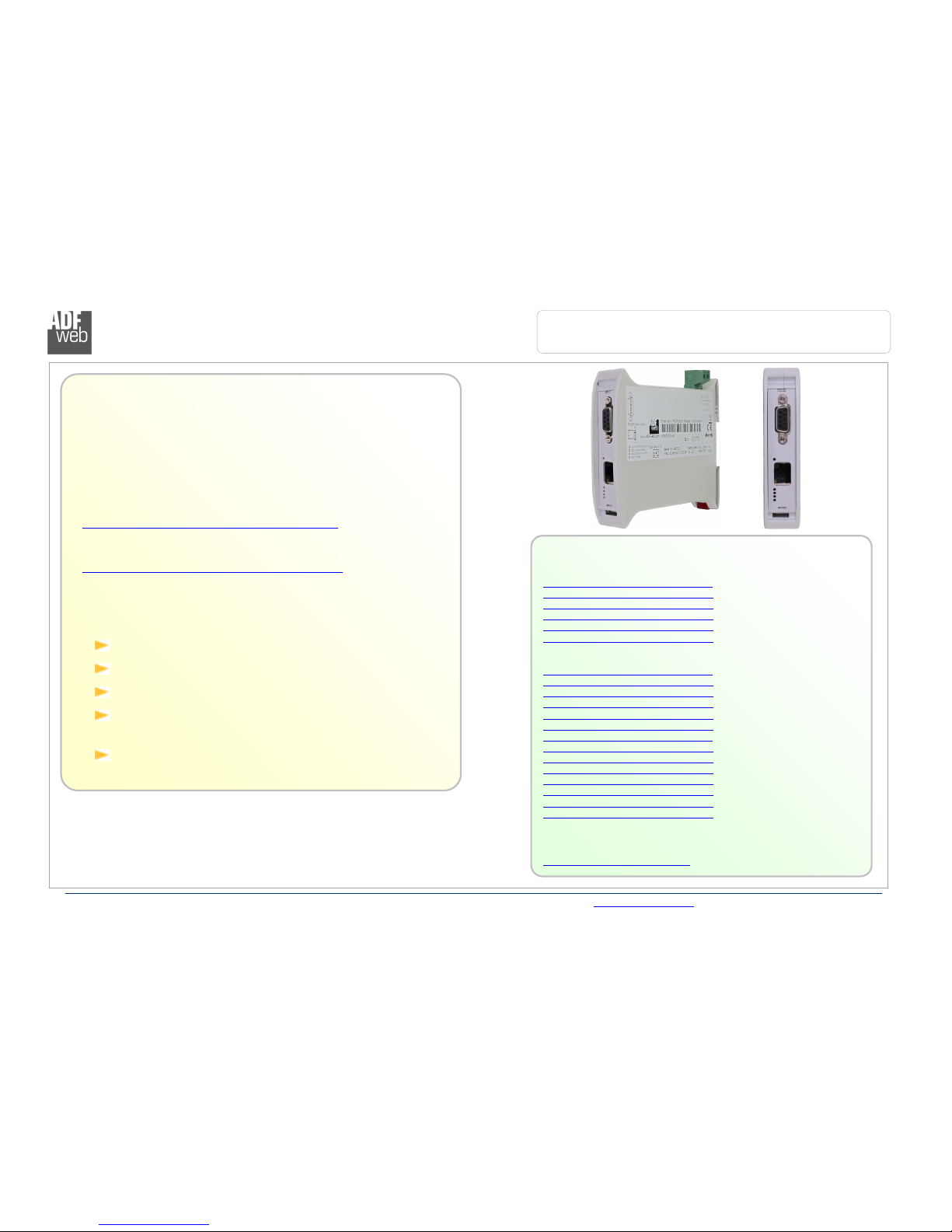
PROFIBUS Master / Ethernet - Converter
(Order Code: HD67575-A )
for Website information:
http://www.adfweb.com/?Product=HD67575
for Price information:
http://www.adfweb.com/?Price=HD67575-A
Benefits and Main Features:
Very easy to configure
PROFIBUS up to 6Mbps
Free software for interfacing to the device
Commands available for develop your own
program
Temperature range:
-40°C / 85°C (-40°F / 85°F)
For others PROFIBUS devices, see also the following links:
PROFIBUS Master from/to …
www.adfweb.com?Product=HD67570 (… Devi eNet Slave)
www.adfweb.com?Product=HD67577 (… CAN)
www.adfweb.com?Product=HD67579 (… Modbus TCP Slave)
www.adfweb.com?Product=HD67580 (… Modbus Slave)
www.adfweb.com?Product=HD67593 (… EtherNet/IP)
www.adfweb.com?Product=HD67604 (… PROFINET)
PROFIBUS Slave from/to …
www.adfweb.com?Product=HD67045 (… Serial)
www.adfweb.com?Product=HD67053 (… M-Bus Master)
www.adfweb.com?Product=HD67252 (… NMEA 2000)
www.adfweb.com?Product=HD6755 (… CANopen)
www.adfweb.com?Product=HD67552 (… CAN)
www.adfweb.com?Product=HD67553 (… J1939)
www.adfweb.com?Product=HD67555 (… Devi eNet Master)
www.adfweb.com?Product=HD6756 (… Modbus Master)
www.adfweb.com?Product=HD67562 (… Modbus Slave)
www.adfweb.com?Product=HD67563 (… Ethernet Server)
www.adfweb.com?Product=HD67564 (… Modbus TCP Client)
www.adfweb.com?Product=HD67565 (… Modbus TCP Server)
www.adfweb.com?Product=HD67574 (… Devi eNet Slave)
www.adfweb.com?Product=HD67576 (… Ethernet Server)
Do you need to choose a device? do you want help?
Ask it to the following link:
www.adfweb.com?Cmd=helpme
Industrial Electronic Devices
ADFweb.com Srl – IT31010 – Mareno – Treviso INFO: www.adfweb.com hone +39.0438.30.91.31
User Manual
PROFIBUS
Master
/ Ethernet
Document code: MN67575_ENG Revision 2.0 Page 2 of 34
INDEX:
Page
INDEX 2
UPDATED DOCUMENTATION 2
REVISION LIST 2
WARNING 2
TRADEMARKS 2
SECURITY ALERT 3
EXAMPLE OF CONNECTION 4
CONNECTION SCHEME 5
CHARACTERISTICS 7
CONFIGURATION 7
POWER SUPPLY 8
FUNCTION MODES 9
LEDS 0
PROFIBUS 2
ETHERNET 2
USE OF COMPOSITOR SW67575 3
NEW PROJECT / OPEN PROJECT 3
SET COMMUNICATION 4
PROFIBUS NETWORK 5
MASTER PROFIBUS OPTIONS 6
PROFIBUS DEVICE 7
-M
ODULE
S
ELECTION
8
-
U
SER
P
ARAMETERS
20
-
M
ODULE
P
ARAMETERS
22
-
C
APABILITIES
23
-
O
PTIONS
24
UPDATE DEVICE 25
ETHERNET PROTOCOL 27
MECHANICAL DIMENSIONS 32
ORDER CODE 32
ACCESSORIES 32
DISCLAIMER 33
OTHER REGULATIONS AND STANDARDS 33
WARRANTIES AND TECHNICAL SUPPORT 34
RETURN POLICY 34
PRODUCTS AND RELATED DOCUMENTS 34
Pagina 2 di 34
UPDATED DOCUMENTATION:
Dear customer, we thank you for your attention and we remind you that
you need to check that the following document is:
Updated;
Related to the product you own.
To obtain the most recently updated document, note the “document code”
that appears at the top right-hand corner of each page of this document.
With this “Document Code” go to web page www.adfweb.com/download/
and search for the corresponding code on the page. Click on the proper
“Document Code” and download the updates.
To obtain the updated documentation for the product that you own, note
the “Document Code” (Abbreviated written "Doc. Code" on the label on
the product) and download the updated from our web site
www.adfweb.com/download/
REVISION LIST:
Revision
Date Author
Chapter
Des ription
2.000 08/08/20 2
Fl All Software changed (v .300)
2.0 0 / 2/20 2
Fl All Software changed (v .400)
2.0 09/0 /20 3
Nt All Added new chapters
2.0 2 08/04/20 3
Fl All Revision
WARNING:
ADFweb.com reserves the right to change information in this manual
about our product without warning.
ADFweb.com is not responsible for any error this manual may contain.
TRADEMARKS:
All trademarks mentioned in this document belong to their respective
owners.

Industrial Electronic Devices
ADFweb.com Srl – IT31010 – Mareno – Treviso INFO: www.adfweb.com hone +39.0438.30.91.31
User Manual
PROFIBUS
Master
/ Ethernet
Document code: MN67575_ENG Revision 2.0 Page 3 of 34
SECURITY ALERT:
G
ENERAL
I
NFORMATION
To ensure safe operation, the device must be operated according to the instructions in the manual. When using the device are required for
each individual application, legal and safety regulation. The same applies also when using accessories.
I
NTENDED
U
SE
Machines and systems must be designed so the faulty conditions do not lead to a dangerous situation for the operator (i.e. independent limit
switches, mechanical interlocks, etc.).
Q
UALIFIED
P
ERSONNEL
The device can be used only by qualified personnel, strictly in accordance with the specifications.
Qualified personnel are persons who are familiar with the installation, assembly, commissioning and operation of this equipment and who
have appropriate qualifications for their job.
R
ESIDUAL
R
ISKS
The device is state of the art and is safe. The instrument can represent a potential hazard if they are inappropriately installed and operated
by personnel untrained. These instructions refer to residual risks with the following symbol:
This symbol indicates that non-observance of the safety instructions is danger for people to serious injury or death and / or the
possibility of damage.
CE
CONFORMITY
The declaration is made by us. You can send an email to support@adfweb.com or give us a call if you need it.

Industrial Electronic Devices
ADFweb.com Srl – IT31010 – Mareno – Treviso INFO: www.adfweb.com hone +39.0438.30.91.31
User Manual
PROFIBUS
Master
/ Ethernet
Document code: MN67575_ENG Revision 2.0 Page 4 of 34
EXAMPLE OF CONNECTION:
Used in pair with the HD67576-A1, allows to make a tunneling over Ethernet. In both cases you can also connect them to Internet.
Industrial Electronic Devices
ADFweb.com Srl – IT31010 – Mareno – Treviso INFO: www.adfweb.com hone +39.0438.30.91.31
User Manual
PROFIBUS
Master
/ Ethernet
Document code: MN67575_ENG Revision 2.0 Page 5 of 34
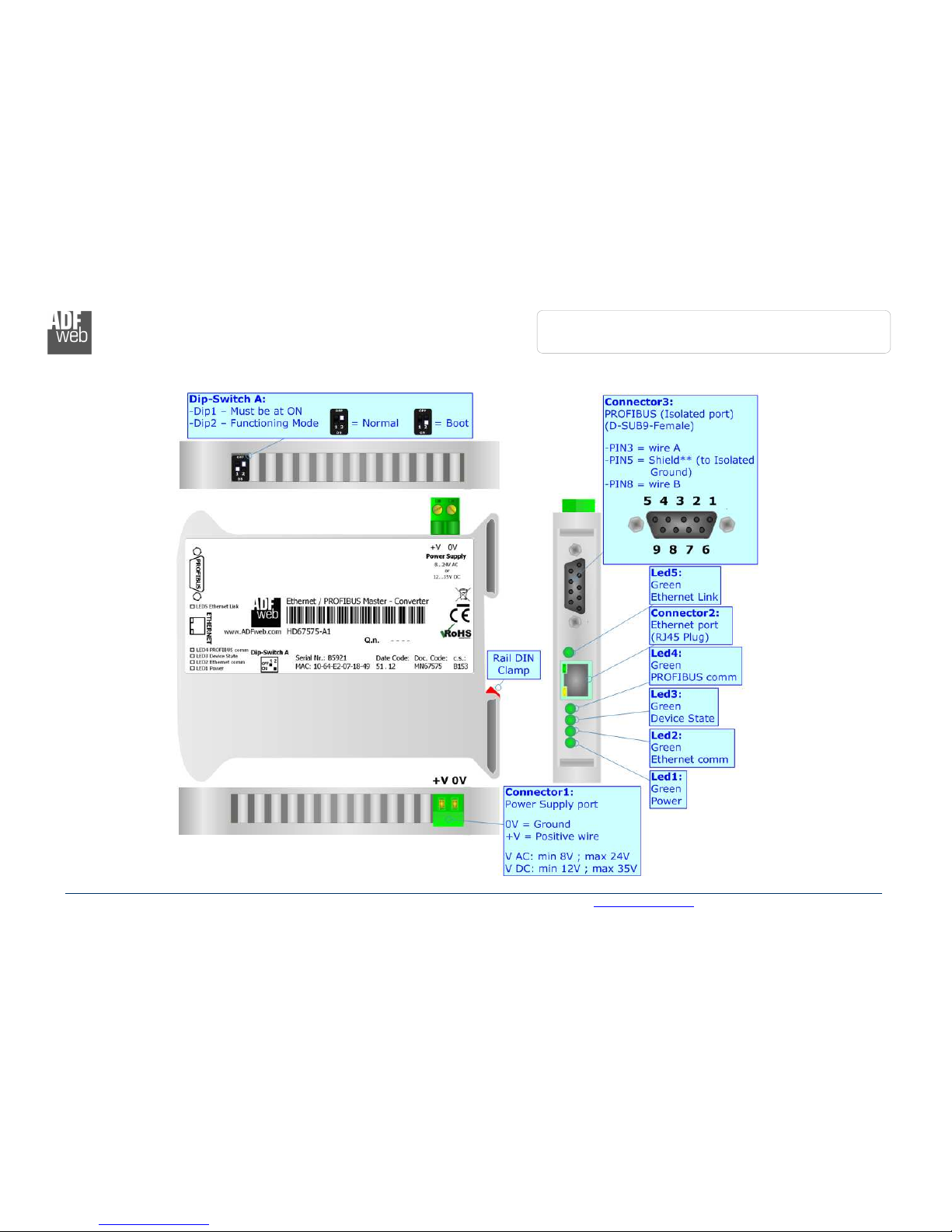
CONNECTION SCHEME:
Figure
1
a
: Connection scheme for HD67
575
-
A1 with c.s.: B153
Industrial Electronic Devices
ADFweb.com Srl – IT31010 – Mareno – Treviso INFO: www.adfweb.com hone +39.0438.30.91.31
User Manual
PROFIBUS
Master
/ Ethernet
Document code: MN67575_ENG Revision 2.0 Page 6 of 34
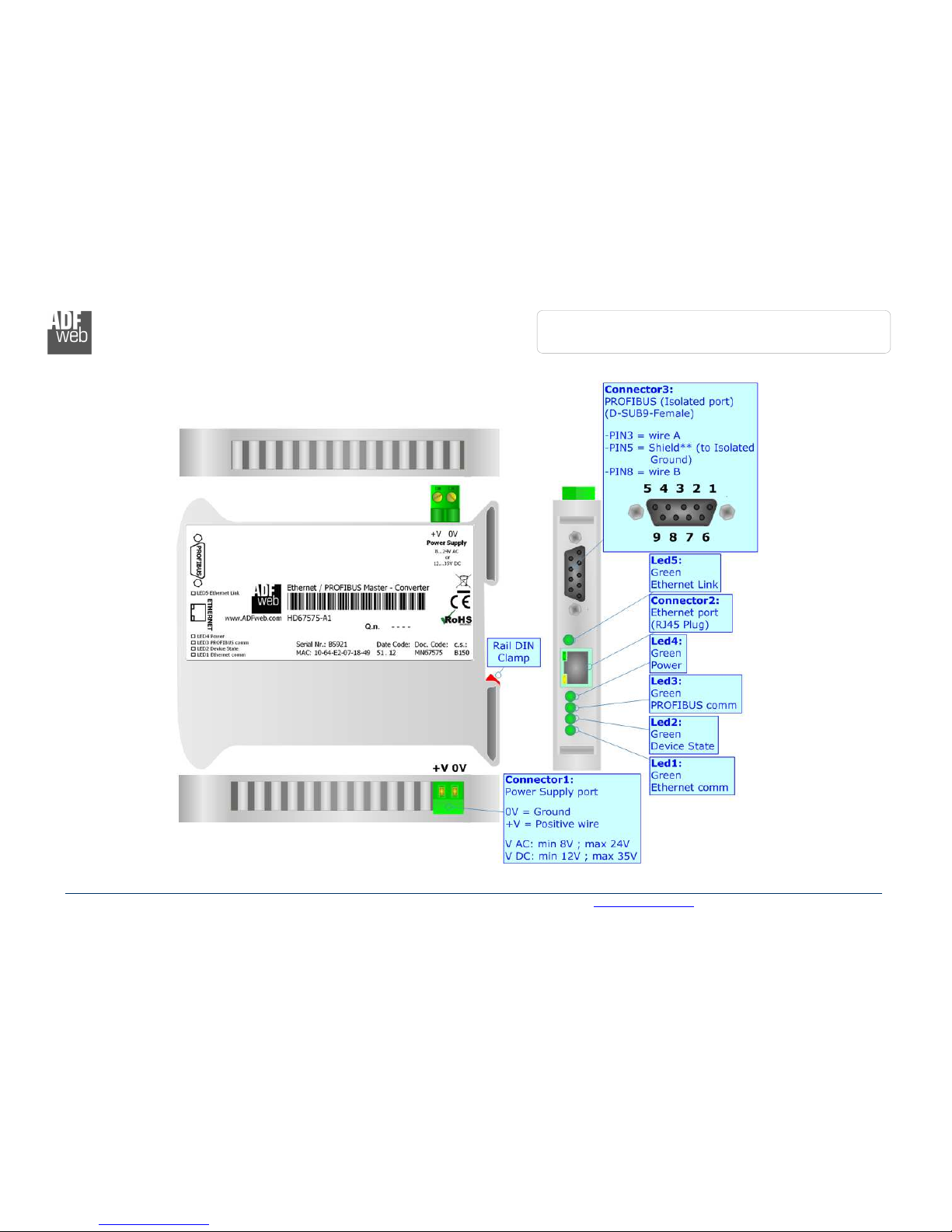
Figure
1b
: Connection scheme for HD67
575
-
A1 with c.s.: B150

Industrial Electronic Devices
ADFweb.com Srl – IT31010 – Mareno – Treviso INFO: www.adfweb.com hone +39.0438.30.91.31
User Manual
PROFIBUS
Master
/ Ethernet
Document code: MN67575_ENG Revision 2.0 Page 7 of 34
CHARACTERISTICS:
The configurable “PROFIBUS Master / Ethernet” converter allows the following characteristics:
TCP/IP and UDP protocol at Ethernet side;
Triple isolation between Ethernet /PROFIBUS, Ethernet /Power Supply, PROFIBUS/Power Supply.
Mountable on 35mm Rail DIN;
Power Supply 8...24V AC or 2...35V DC;
Temperature range -40°C to 85°C.
CONFIGURATION:
You need Compositor SW67575 software on your PC in order to perform the following:
Define the parameter of the PROFIBUS;
Define the parameter of the Ethernet;
Define the PROFIBUS network.
Industrial Electronic Devices
ADFweb.com Srl – IT31010 – Mareno – Treviso INFO: www.adfweb.com hone +39.0438.30.91.31
User Manual
PROFIBUS
Master
/ Ethernet
Document code: MN67575_ENG Revision 2.0 Page 8 of 34
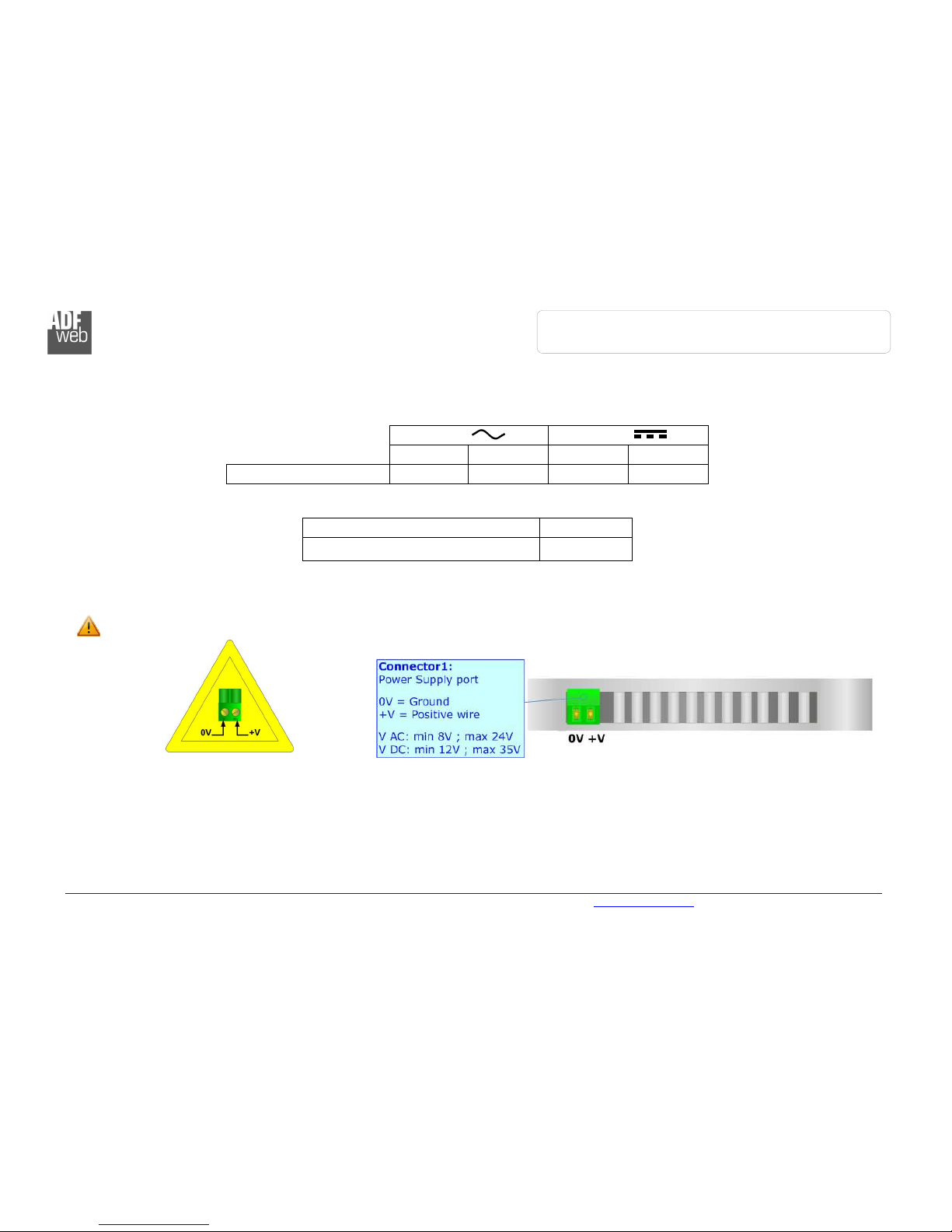
POWER SUPPLY:
The device can be powered between a wide range of tensions. For more details see the two tables below.
VAC
VDC
Vmin Vmax Vmin Vmax
HD67575-A1 8V 24V 12V 35V
Consumption at 24V DC:
Devi e W/VA
HD67575-A 4
Caution: Not reverse the polarity power
HD67
575
-
A

Industrial Electronic Devices
ADFweb.com Srl – IT31010 – Mareno – Treviso INFO: www.adfweb.com hone +39.0438.30.91.31
User Manual
PROFIBUS
Master
/ Ethernet
Document code: MN67575_ENG Revision 2.0 Page 9 of 34
FUNCTION MODES:
HD67575-A1
WITH C
.
S
.
B153
The device has got two functions mode depending of the position of the Dip2 of ‘Dip-Switch A’:
The first, with Dip2 in Off position (factory setting), is used for the normal working of the device.
The second, with Dip2 in On position, is used for upload the Project/Firmware.
Warning:
Dip of ‘Dip-Switch A’ must be at ON position for working even if the Ethernet cable isn’t inserted.
HD67575-A1
WITH C
.
S
.
B150
The device has got two functions mode:
The first, Normal Mode, is used for the normal working of the device.
The second, Boot Mode, is used for upload the Project.
For the operations to follow for the updating (see ‘UPDATE DEVICE’ section).
According to the functioning mode, the LEDs will have specifics functions (see ‘LEDS’ section).
Industrial Electronic Devices
ADFweb.com Srl – IT31010 – Mareno – Treviso INFO: www.adfweb.com hone +39.0438.30.91.31
User Manual
PROFIBUS
Master
/ Ethernet
Document code: MN67575_ENG Revision 2.0 Page 0 of 34
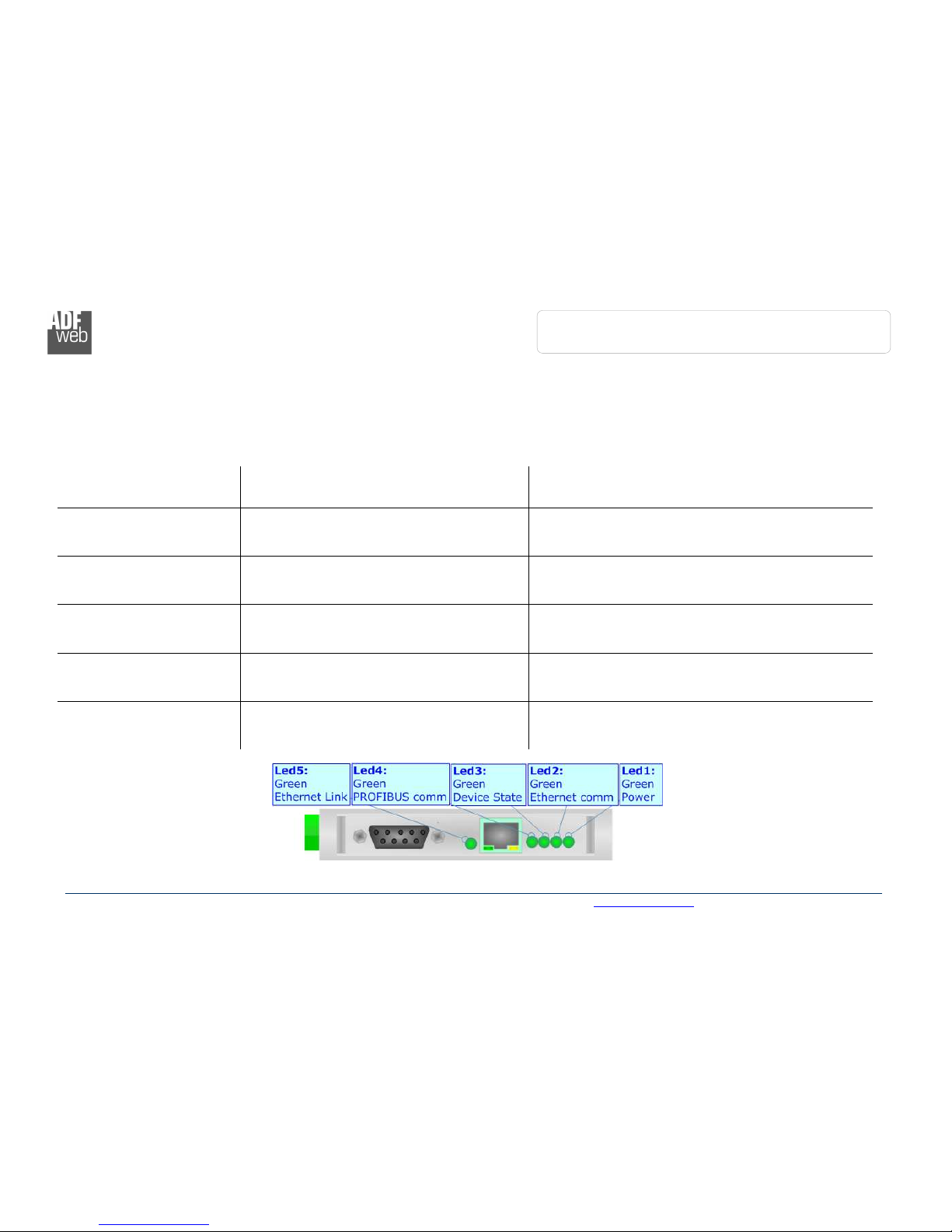
LEDS:
The device has got five LEDs that are used to give information of the functioning status.
The various meanings of the LEDs are described in the table below.
HD67575-A1
WITH C
.
S
.
B153
LED Normal Mode Boot Mode
: Power (green) ON: Powered
OFF: Not powered
ON: Powered
OFF: Not powered
2: Ethernet comm (green) Blinks quickly when receive Ethernet commands Blinks qui kly: Boot state
Blinks very slowly (~0.5Hz): update in progress
3: Device State (green) Blinks slowly (~ Hz) Blinks qui kly: Boot state
Blinks very slowly (~0.5Hz): update in progress
4: PROFIBUS comm (green) Blinks quickly when there is PROFIBUS
communication
Blinks qui kly: Boot state
Blinks very slowly (~0.5Hz): update in progress
5: Ethernet Link (green) ON: Ethernet cable connected
OFF: Ethernet cable disconnected
ON: Ethernet cable connected
OFF: Ethernet cable disconnected

Industrial Electronic Devices
ADFweb.com Srl – IT31010 – Mareno – Treviso INFO: www.adfweb.com hone +39.0438.30.91.31
User Manual
PROFIBUS
Master
/ Ethernet
Document code: MN67575_ENG Revision 2.0 Page of 34
HD67575-A1
WITH C
.
S
.
B150
LED Normal Mode Boot Mode
: Ethernet comm (green) Blinks quickly when receive Ethernet commands Blinks qui kly: Boot state
Blinks very slowly (~0.5Hz): update in progress
2: Device State (green) Blinks slowly (~ Hz) Blinks qui kly: Boot state
Blinks very slowly (~0.5Hz): update in progress
3: PROFIBUS comm (green) Blinks quickly when there is PROFIBUS
communication
Blinks qui kly: Boot state
Blinks very slowly (~0.5Hz): update in progress
4: Power (green) ON: Powered
OFF: Not powered
ON: Powered
OFF: Not powered
5: Ethernet Link (green) ON: Ethernet cable connected
OFF: Ethernet cable disconnected
ON: Ethernet cable connected
OFF: Ethernet cable disconnected
Industrial Electronic Devices
ADFweb.com Srl – IT31010 – Mareno – Treviso INFO: www.adfweb.com hone +39.0438.30.91.31
User Manual
PROFIBUS
Master
/ Ethernet
Document code: MN67575_ENG Revision 2.0 Page 2 of 34
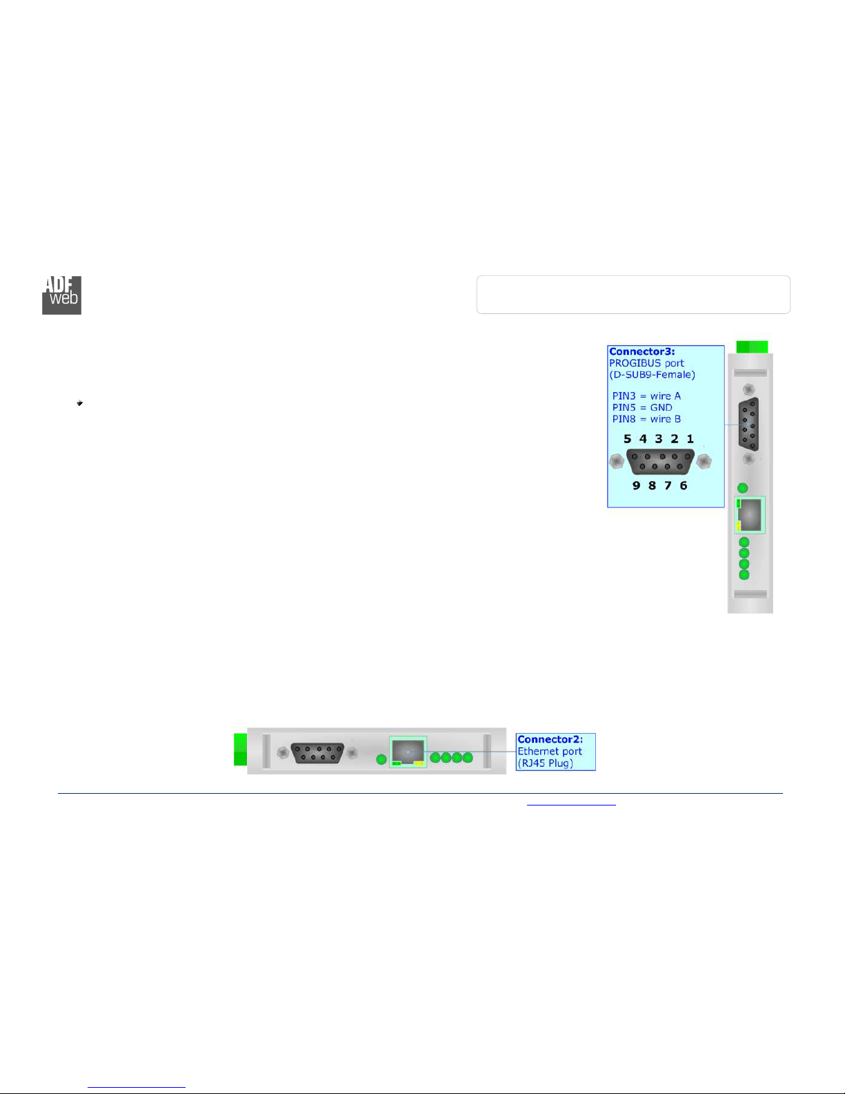
PROFIBUS:
The PROFIBUS uses a 9-pin D-SUB connector. The pin assignment is defined like in the right figure.
Here some codes of cables:
Belden: p/n 83079A - Continuous Armor DataBus® ISA/SP-50 PROFIBUS Cable.
ETHERNET:
The Ethernet connection must be made using Connector2 of HD67575-A with at least a Category 5E cable. The maximum length of the
cable should not exceed 00m. The cable has to conform to the T568 norms relative to connections in cat.5 up to 00 Mbps. To connect the
device to an Hub/Switch is recommended the use of a straight cable, to connect the device to a PC/PLC/other is recommended the use of a
cross cable.
Industrial Electronic Devices
ADFweb.com Srl – IT31010 – Mareno – Treviso INFO: www.adfweb.com hone +39.0438.30.91.31
User Manual
PROFIBUS
Master
/ Ethernet
Document code: MN67575_ENG Revision 2.0 Page 3 of 34
USE OF COMPOSITOR SW67575:
To configure the Converter, use the available software that runs with
Windows, called SW67575. It is downloadable on the site
www.adfweb.com and its operation is described in this document.
(This manual is referenced to the last version of the software present
on our web site). The software works with MSWindows (MS 2000, XP,
Vista, Seven, 8; 32/64bit).
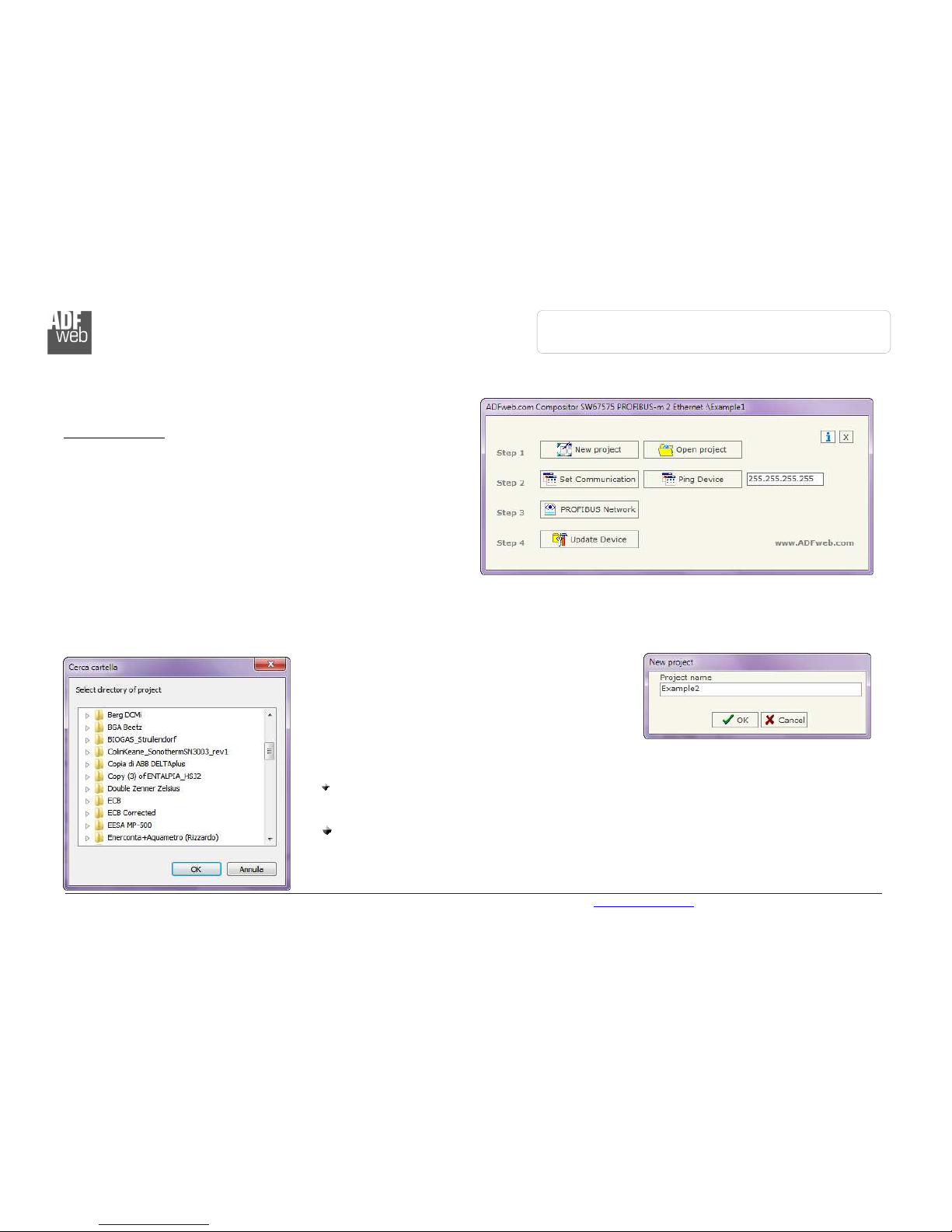
When launching the SW67575 the right window appears (Fig. 2).
NEW PROJECT / OPEN PROJECT:
The “New Proje t” button creates the folder which contains the entire device configuration.
A device configuration can also be imported or exported:
To clone the configurations of a programmable “PROFIBUS Master / Ethernet” Converter in
order to configure another device in the same manner, it is necessary to maintain the folder
and all its contents;
To clone a project in order to obtain a different version of the project, it is sufficient to
duplicate the project folder with another name and open the new folder with the button
“Open Proje t”.
Figure 2: Main window for SW67575

Industrial Electronic Devices
ADFweb.com Srl – IT31010 – Mareno – Treviso INFO: www.adfweb.com hone +39.0438.30.91.31
User Manual
PROFIBUS
Master
/ Ethernet
Document code: MN67575_ENG Revision 2.0 Page 4 of 34
SET COMMUNICATION:
This section defines the fundamental communication parameter of two buses, PROFIBUS and Ethernet.
By pressing the “Set Communi ation” button from the main window for SW67575 (Fig. 2) the window
“Set Communication” appears (Fig. 3).
The window is divided in two sections, one for the PROFIBUS and the other for the Ethernet.
The means of the fields for “PROFIBUS” are:
In the field “ID Dev.” the address of the PROFIBUS side is defined;
In the field “Baud rate” the baud rate for the PROFIBUS side is defined;
The means of the fields for “Ethernet” are:
In the field “IP ADDRESS” insert the IP address;
In the field “SUBNET Mask” insert the SubNet Mask;
If the “GATEWAY” field is checked it is possible to insert, in the field under, the IP Address for going
out to the net;
In the field “Port” insert the number of the port;
In the field “COMPANION BOARD IP ADDRESS” insert the IP address of the Ethernet Client
device that communicates with the HD67575-A ;
In the field “COMPANION Port” insert the number of the port of the Ethernet Client device that
communicates with the HD67575-A .
Warning:
Fields “COMPANION BOARD IP ADDRESS” and “COMPANION Port” are used only if the HD67575 device is connected to the
HD67576-A .
Figure 3: “Set Communication” window
Industrial Electronic Devices
ADFweb.com Srl – IT31010 – Mareno – Treviso INFO: www.adfweb.com hone +39.0438.30.91.31
User Manual
PROFIBUS
Master
/ Ethernet
Document code: MN67575_ENG Revision 2.0 Page 5 of 34
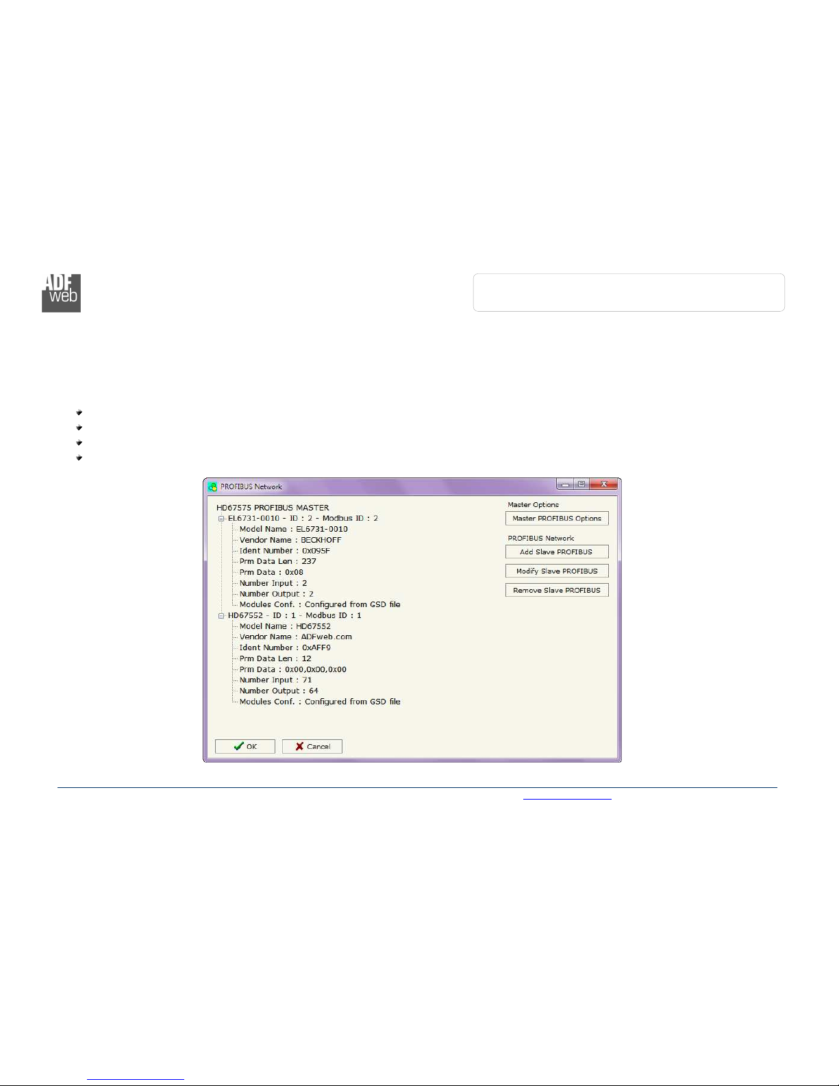
PROFIBUS NETWORK:
By pressing the “PROFIBUS Network” button from the main window for SW67575 (Fig. 2) the window “PROFIBUS Network” (Fig. 4)
appears.
In this window is possible to:
Modify the PROFIBUS Master Options (“Master PROFIBUS Options”);
Add a PROFIBUS Slave in the Network of the Master (“Add Slave PROFIBUS”);
Modify a PROFIBUS Slave in the Network (“Modify Slave PROFIBUS”);
Remove a PROFIBUS Slave from the Network (“Remove Slave PROFIBUS”).
Figure 4: “ ROFIBUS Network” window

Industrial Electronic Devices
ADFweb.com Srl – IT31010 – Mareno – Treviso INFO: www.adfweb.com hone +39.0438.30.91.31
User Manual
PROFIBUS
Master
/ Ethernet
Document code: MN67575_ENG Revision 2.0 Page 6 of 34
MASTER PROFIBUS OPTIONS:
By pressing the “Master PROFIBUS Options” button from the “PROFIBUS Network” window (Fig. 4) the “PROFIBUS Master Options”
window appears (Fig. 5).
In this window is possible to set the WatchDog Time for the PROFIBUS Slaves.
Note:
Fact and Fact2 could be write in decimal o hexadecimal (with prefix “0x” or “$”) and the values must between and 255
Warning:
The WatchDog time must be between 200 and 650250 milliseconds.
Figure 5: “ ROFIBUS Master Options” window
Industrial Electronic Devices
ADFweb.com Srl – IT31010 – Mareno – Treviso INFO: www.adfweb.com hone +39.0438.30.91.31
User Manual
PROFIBUS
Master
/ Ethernet
Document code: MN67575_ENG Revision 2.0 Page 7 of 34
PROFIBUS DEVICE:
By pressing the “Add Slave PROFIBUS” and “Modify Slave PROFIBUS” button (or double click above an existent PROFIBUS Slave) from
the “PROFIBUS Network” window (Fig. 4) the “PROFIBUS Device” window appears (Fig. 6).
In this window is possible to:
Set the PROFIBUS Slave ID (“ID Slave PROFIBUS”);
Select the Modules present
in the PROFIBUS Slave
from the Available Modules
in GSD file (“Module
Sele tion”);
Modify the User Parameters
(if present) of the
PROFIBUS device (“User
Parameters”);
Modify the Parameters (if
present) of the Module
Selected (“Module
Parameters”);
Watch Features and
Baudrate supported from
the PROFIBUS device
(“Capabilities”);
Select the Sync, Freeze
and Reset of Data Options
(“Options”).
Figure 6: “ ROFIBUS Device” window

Industrial Electronic Devices
ADFweb.com Srl – IT31010 – Mareno – Treviso INFO: www.adfweb.com hone +39.0438.30.91.31
User Manual
PROFIBUS
Master
/ Ethernet
Document code: MN67575_ENG Revision 2.0 Page 8 of 34
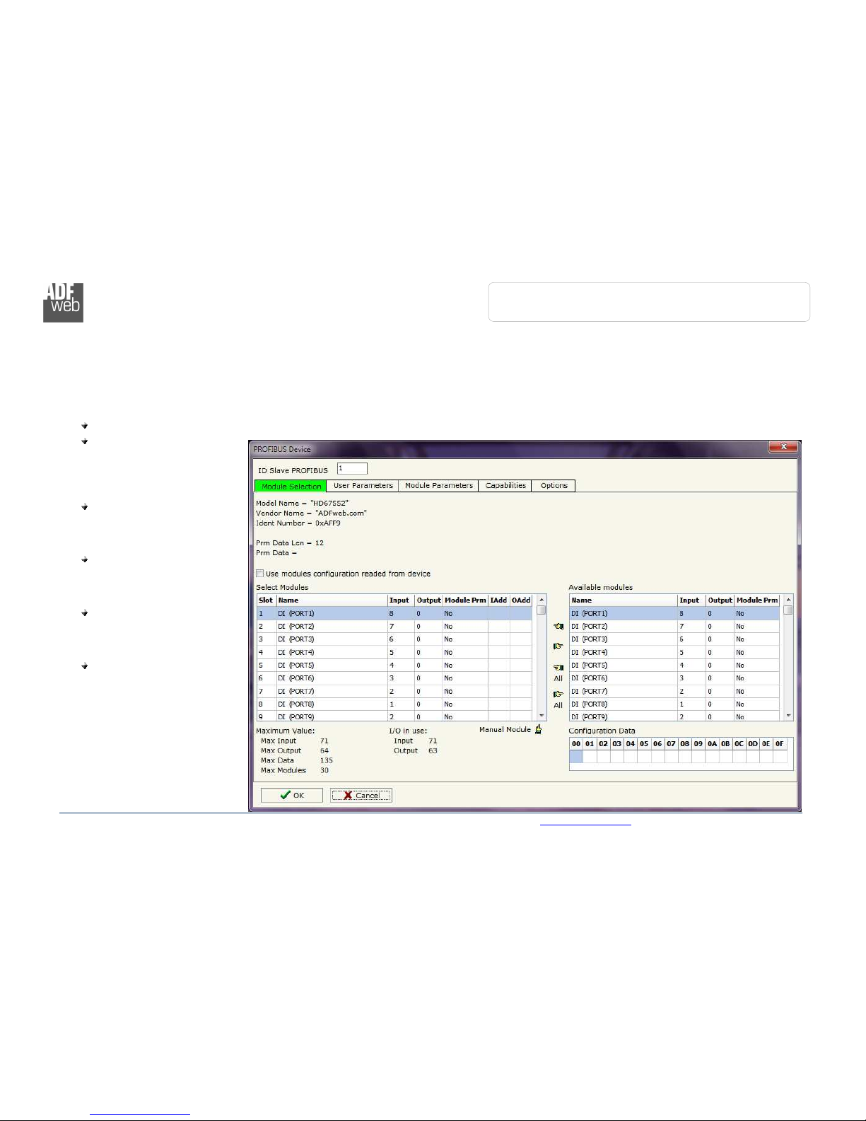
M
ODULE
S
ELECTION
:
The section “Module Selection” is used to select
which Modules are present in the Slave (Fig. 7).
In this section is possible to:
Check the list of the Modules selected (“Select
Modules”) (Fig. 7, point ( )) and the list of
Modules Available in GSD file (“Available
Modules") (Fig. 7, point (7));
Add a Module from the list of GSD file (Fig. 7,
point (6));
Remove a Module from selected list (Fig. 7,
point (5));
Add all Modules present in the GSD file (Fig.
7, point (4));
Remove all Modules from selected list (Fig. 7,
point (3));
Insert a Module not present in the GSD file
(“Manual Module”) (Fig. 7 point (2)). For
more info see the section “Manual Module”
below;
Enable the read of configuration directly from
the PROFIBUS Slave (“Use module
onfiguration readed from devi e”) (Fig 7,
point (8)). If this option is enable the
configuration of the modules is discorded and
the device read the correct configuration
directly to the PROFIBUS slave.
Figure 7: “ ROFIBUS Device – Module Selection”
window

Industrial Electronic Devices
ADFweb.com Srl – IT31010 – Mareno – Treviso INFO: www.adfweb.com hone +39.0438.30.91.31
User Manual
PROFIBUS
Master
/ Ethernet
Document code: MN67575_ENG Revision 2.0 Page 9 of 34
By pressing the “Manual Module” button from the “PROFIBUS Device” window (Fig. 6) the “Add Module Manually” window appears (Fig. 8).
In this window is possible to add a Module manually, i.e. writing the configuration of the module (in hexadecimal).
The means of the fields are:
In the field “Des ription of Module” a name of the Module is defined;
In the field “Insert the Configuration of Module (HEX)” the
configuration of the module is defined. The configuration must be write
in hexadecimal mode (without prefix “0x” o “$”).
To modify a Module inserted manually, is neccessary to do a double click on
the module to change in the “Select Module” list (Fig. 7, point ( )). It is
possible to change only the module inserted manually.
Note:
The Values inserted in the table must between 00 and FF
Figure 8: “Add/Modify Module Manually” window
Industrial Electronic Devices
ADFweb.com Srl – IT31010 – Mareno – Treviso INFO: www.adfweb.com hone +39.0438.30.91.31
User Manual
PROFIBUS
Master
/ Ethernet
Document code: MN67575_ENG Revision 2.0 Page 20 of 34
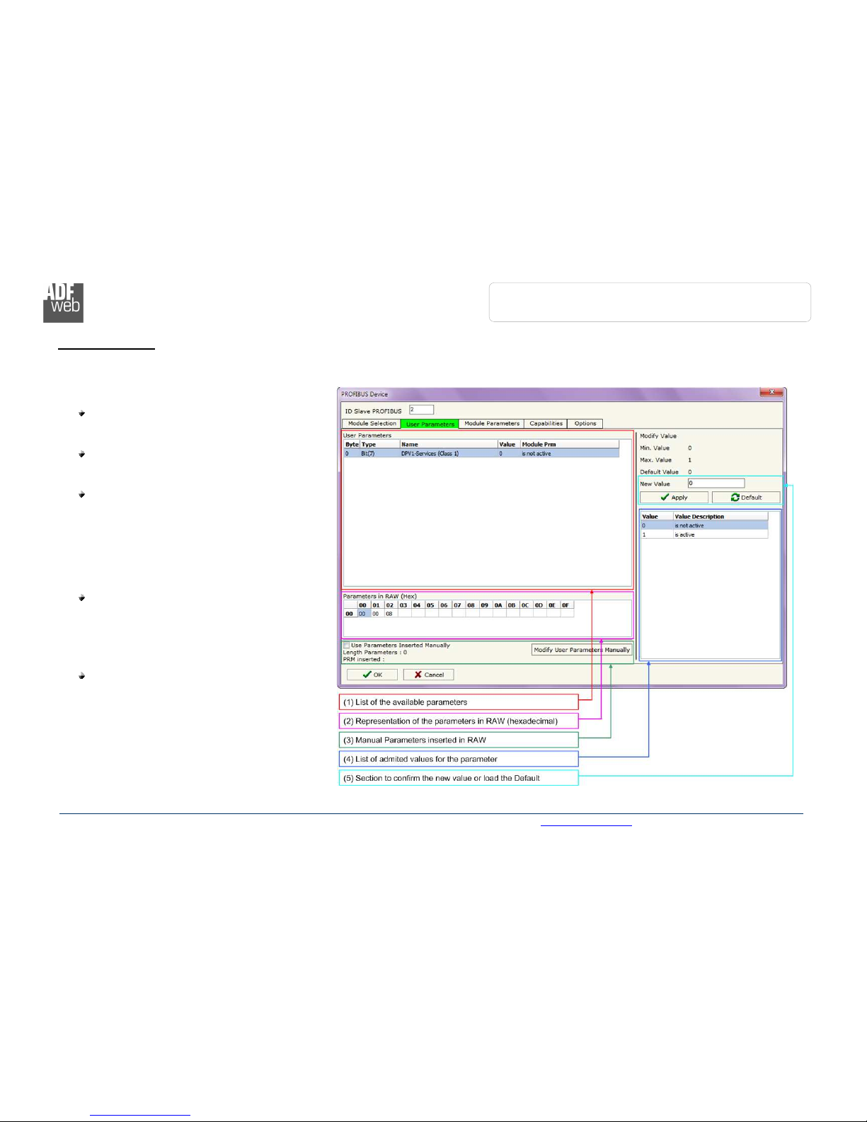
U
SER
P
ARAMETERS
:
The section “User Parameters” is used to modify the parameters of the PROFIBUS slave (Fig. 9).
In this section there are:
The List of all Parameters available for the
PROFIBUS device (“User Parameters”) (Fig.
9, point ( ));
The Configuration of all parameters in RAW
(“Parameters in RAW (Hex)”) (Fig. 9,
point(2));
The “Use Parameter Inserted Manually”,
enable this option is possible to insert
manually the parameters of Device and also
of the Modules. Using the “Modify User
Parameters Manually” button is possible
to insert/modify the parametrization of the
device (and/or modules). For more info see
below. (Fig. 9, point(3));
The admited value for the selected
parameter. It is possible to select the value
desired and confirm it with the “Apply”
button. If no value appears in this table, the
“Min Value” and “Max Value” are the limit of
the parameter. (Fig. 9, point(4));
The “Apply” button is used to confirm the
new value of the parameter, the “Default”
button is used to load the factory value for
the parameter. In “New Value” edit box it
is possible to set the new value. (Fig. 9,
point(5)).
Figure 9: “ ROFIBUS Device – User arameters” window
Table of contents
Other ADF Wed Media Converter manuals

Popular Media Converter manuals by other brands


Teletechnika Ltd.
Teletechnika Ltd. DHD-1000 Technical documentation/user guide

Meinberg
Meinberg XHE-Rubidium manual

Konica Minolta
Konica Minolta ZCW-100 instruction manual

Allied Telesis
Allied Telesis AT-MC115XL installation guide

TRENDnet
TRENDnet TFC-1600 user guide

ADF Web
ADF Web HD67D34-B2-868MHz user manual