ADINA TITAN Series User manual
Inverter Ceiling Floor
User Manual
Models
36K 60K
User manual - Inverter Ceiling Floor

1
PRECAUTION
Read the following PRECAUTIONS carefully before installation.
The air conditioner must be installed by professional technicians.
The installation should be done in accordance with the manual.
Please forgive delay of notice in case of any advancement.
PRECAUTIONS -----------------------------------------------------2
Content
Usage
PARTS AND FUNCTIONS ----------------------------------------- 4
OPERATION AND PERFORMANCE ---------------------------------6
MAINTENANCE----------------------------------------------------------- 7
TROUBLE SHOOTING ----------------------------------------------- 9-
Installation
PREPARATION BEFORE INSTALLATION ------------------------11
INDOOR UNIT INSTALLATION-----------------------------------12
DRAINAGE PIPE CONNECTION -----------------------------------16
OUTDOOR UNIT INSTALLATION --------------------------------16
REMOTE CONTROLLER -------------------------------------------
28
USAGE
2
Please read thelable on theprincipal unit carefully.
Read the following " PRECAUTIONS" carefully before installation.
The caution items stated here must be followed because these important contents are related
to safety. The meaning of each indication used is as below.
Incorrect installation due to ignoring of the instruction will cause harm or damage, and the
seriousness is classified by the following indications.
!This indication shows the possibility of causing death or serious injury.
This indication shows the possibility of causing injury or damage to
properties only.
WARNING
!CAUTION
PRECAUTIONS
In case ofsuch abnormal situationsas abnormal noise,smelliness, smoke, temperaturerising,
electrical leakage, fire,please cut off the electricsupply quickly andcontact the dealer.
6
.
CAUTION
Warning
Engage dealer orspecialist for installation.If installation doneby user isdefective, it will
cause water leakage,electrical shock orfire.
Professional persons arenot allowed todismantel the unit,otherwise,accident or damage
may occur.
Please do notuse ort storesuch flammable gasor liquid ashair styling jelly, oil paint,petrol in
case of fire.
The major electricalsupply should beinstalled out of children touch .
Please do notspray water orother liquid incase of danger.
Please do nottouch the unitwith wet handsin case ofelectric shock.
Please cut offthe electrical supplyin lightning andrainy days, othwewise,danger or
damage may occur.
Please cut offthe major electricalsupply when itis not usedfor a long time to
avoid accidents.
Never put hands or objects into the air inlet and outlet of the indoor and outdoor unit, in case the fan with
high speed may hurt you.
The baffle of the outdoor unit is not allowed to be dismantled because the fan with high speed may
cause injury.
Do not letthe indoor unit or remote controller be affected with damp, otherwise ,Short
circuit or damagemay occur.
Make sure theis totally closedafter the ashscreen is cleaned.
Do not letit open for a long time in case ofany danger.

Do not attempt to install this unit by yourself. This unit requires installation by qualified
persons, or will cause users harmed, burned electrical shocked.
Symbol Icon
Meaning Meaning
Mistaken operation/use may cause
death or serious injury.
Mistaken operation/use may cause
injury or damage of properties only.
1. Injury means causing harmed,burned, electrical
shocked,but not serious for hospitalization.
2. Damage of property means disrepair of property,
material.
Contents prohibited are represented
by nots or figures.
Execution in force. Iterms forcibly executed
are represented by notes or figures.
Notices (including warning)items noticed
and warned are represented by the notes
or figures
Confirm if it is grounded properly. If not, it may cause electrical shock.
When installing in air conditioner a small room,measures should be taken to avoid
suffocation, while the leakage of refrigerant accumulates the limited density.
Consukt our dealers for details.
Never put hands or objects into the air outlet/inlet of indoor or outdoor units. These units are
installed with a fan running at high speed. To touch the moving fan will cause serious injury.
When exceptions occuring, such as smelling odors, power should be
switched offat once and contact our dealers , or may cause person injury or fire
Descrition of symbols Description of icon
Warning
Notice
!
Professional installation
Measures of no lessthan
limited density
Prohibition
Confirm grounded wire
Poweroff
!
!
Warning
!
Do not install the AC in the place where flammable gasis prone to leaking. If flammable gas
leaks and surrounds the AC, fire may be caused
Ensure that the base of installation is firm.
If not firm, the accident of AC's crush may occur
Ensure that electric system has installed creepage protector.
Lack of creepage protector may cause electric shock or fire.
Insta-
llation
Confirm
Location
Confirm
Fixture
Confirm
electric leakage
protector
prohibition
Please check the base of installation is firm and perfect when running for a long time. If not,
the accident of AC's crush may occur and cause injury or death of persons.
Please disconnect manual switch to stop running while sweeping.
If not, high speed fan may cause damage.
Please choose the proper fuse.
It is prohibited to use substitution or it may cause obstacle or fire
Check
installation
base
Disconnect
manual switch
Prohibition
Prohibit spraying flammable spray to outdoor unit, or may cause fire.
Usage
3

PARTS AND FUNCTIONS
Air Outlet
Refrigerant Pipe Junction
Filter
Air Outlet
Refrigerant Pipe Junction
Filter
1
2
3
4
5
6
7
Remote controller receiver
Refrigerant connection pipe
Stop valve
Air Outlet grille
Remote controller
Remote controller receiver
Refrigerant connection pipe
Stop valve
Air Outlet grille
Remote controller
8
DISPLAYPANEL
Infrared signal receiver: receive thesignal from theremote controller.
To make your remote controller operation more efficient, please let remote controller
emittor aim atinfrared signal receiver.
Buzzer: firstly powersupplied or any of remote controller operations will make the buzzer
sound once.
Some obstacles occuring in the system will be recognized by intelligent recognition
system of unit,lighting on theDISPLAY PANEL flashing show the type of obstacles.
Requirements
½ø·ç½ø·ç
Do not run the unit until it has been
elctrified for 2 hours. Besides, if the
unitstops for a day and night, please
do not disconnect the power.
Attention not to block the air outlet
and inlet. It may cause the
performance decreasing or start the
protection device so that the unit
cannot run.
DISPLAY PANEL
4
Manual Switch
Nixie tube
Running light Timing light
Defrosting/
preheat light warning light
Buzzer
RUN TIMER
DEFROSTFAULT
13Air inlet
Air outlet
8
ON/OFF
ON/OFF
CLOCK
CLOCKRESET
RESET
HR.
HR.MIN.
MIN.
Outdoor Unit
Indoor Unit
7
6
Air outlet
Air inlet
5
4
2

The protective device maybe trip and stop the unit beyond temp range listed above.
Protection Device (high-pressure)
CUT OFF ELECTRICITY
HEATING CAPACITY
5
If cut off the electricity during operation, all the running will be stopped.
Electrify and restart the unit after the electricity is cut off, the running indicator lamp of the indoor is
flashing to inform you.
Restart the unit till the power recovers.
When the mistaken action occur during operation,please cut off the manual switch in case the mistaken
action occur during operation which is caused by thunder and wireless automobile. After turn it on again,
restart the unit.
Heating is a way that heat pump absorbs heat from outside and release inside.
Once the outside temperature decrease, the heating capacity also decrease.
It is suggest that other heating equipments be used together when outdoor temperature is lower.
The result will be better if the electric auxiliary heater is purchased additionally especially in the low
temperature district.
When the protection device is running, please cut off manually operated
mains switch and restart the unit after the troubles are solved.
It refers to the device which stop automatically when the air conditioner is enforced to run.The indicator
light still flashes when the protection device is on though running has stopped.the checking dictator lamp
flashes when protection device is on. Protection device may start under situations as follows
Refrigeration is running.
The air inlet and outlet of the outdoor unit are choked.
Strong wind goes on blowing outlet of the outdoor unit .
Heating is running
Ash filter of the indoor .unit is overwhelmed with ashes and garbage.
The air outlet of the indoor unit is choked
Feature of heating
Restart the unit at once after stopping or turning it off, compressor will not operate in the first 3min ,this
phenomena is one of system functions(self-protection)
Defrost in the process of HEAT mode
Air conditioner operation conditions
3 minutes protection
When indoor unit operate in the heat mode, no heat air blows out till3-5min after heat exchanger being warm
The outdoor fanmotor may stop runnig during operation if outdoor temperature is high.
Under the condition that indoor unit operate in heat mode and heat exchanger of outdoor unit frosts.
The system will defrost for 2-10 minutes to improve heat effect,at this time drain water from outdoor unit
During defrosting, outdoorand indoor fan motors stop running.
The unit can be operated properly within temp range listed below.
Outside temp
Outside temp
Room temp
Room temp
If the AC runs for a long time in COOL mode at air relative
humidity higher than 80%(doors or windows opened),dew may generate and drip near air outlet.
5 above
43 below
-7 above
21 below
17 above
31 below
Coo-
ling
Room humidity
Heat-
ing

6
Notice the following items to ensure the system operate at best. The specific operation ways refers to
the corresponding content.
Notice the following items to ensure the system operate at best. The specific operation ways refers to
the corresponding content.
Set the temperature properly to make the environment comfortable avoid overheating or overcooling.
Use window curtain or shutter to avoid penetrated sunshine during COOL mode running.
Please close the door and window. If they are open, the cooling & heating efficiency will be worse.
Please preset the running timer by pressing TIMER key of the remote controller.
Do not put objects near the air outlet & inlet ,otherwise air conditioner efficiency will be lower and even the
system will stop running.
The cooling & heating result will be influenced if the air filter is blocked. Please clean the air filter periodically.
Check if the ground wire is connected well.
Check if the air filter is installed well.
You must clean the filter and then start the air conditioner when it is not used for a long time.
Check that the air outlet or inlet of outdoor unit is not blocked.
Check if the ground wire is connected well.
Check if the air filter is installed well.
You must clean the filter and then start the air conditioner when it is not used for a long time.
Check that the air outlet or inlet of outdoor unit is not blocked.
OPERATION AND PERFORMANCE
NOTICE
The unit must be installed by professional technician and users cannot installed by themselves.
Otherwise it may damage the air conditioner or it is dangerous to you.
For proper performance, please refers to the installation manual ,otherwise it may cause self-protection
or dripping, the cooling & heating result reduce.
Please adjust room temperature properly, especially when the old man, children, patients stay at home.
Lightening and other electromagnetic radiation may cause ill effect. If it is, please plug off the power
WARNING
The power plug should not be install at the places where the children can touch, in case they play with
the power plug.
In the stormy weather, please disconnect the power switch, otherwise lightening may damage it.
If the unit not be used for a long time, please cut off the power.
Before cleaning and maintaining the unit, it is safe to disconnect the power switch.
DANGEROUS
Never put hands or objects into the air outlet of indoor or outdoor unit. Otherwise, the moving fan
with high speed will cause serious injury.
Do not touch the louver when it is running or it may clamp your fingers or damage the louver
accessory.
Never dismantle the air-in grille of the outdoor unit. To touch the moving fan at a high speed will
cause serious injury.
It is dangerous for children to play with the air conditioner.
Do not damper the indoor unit and remote controller. Or it may be short circuit and even fire.
Do not use the flammable gas or liquid, such as styling gel, paint, petrol etc. Otherwise fire may
take place.
If abnormal situation happens, such as abnormal noise, smell, smog, temperature rising,
electricity leaking. Please cut off the power immediately and contact with dealers. Do not attempt
to repair the air conditioner yourself.
Do not touch the louver when it is running or it may clamp your fingers or damage the louver
accessory.
It is dangerous for children to play with the air conditioner.
Do not damper the indoor unit and remote controller. Or it may be short circuit and even fire.
Do not use the flammable gas or liquid, such as styling gel, paint, petrol etc. Otherwise fire may
take place.
If abnormal situation happens, such as abnormal noise, smell, smog, temperature rising,
electricity leaking. Please cut off the power immediately and contact with dealers. Do not attempt
to repair the air conditioner yourself.
CHECKS BEFORE OPERATION
BEST OPERATION
SAFETY RULE
Note: To avoid danger, do not replace the power wire by yourself; do not repair the air conditioner yourself.
Malfunction words is shown on the wire controller and give off the sound of buzzer.
The fuse breaks down or the breaker makes a mistake frequently.
External material or water enter into the inside of indoor unit.
Remote controller fail to receive or the switch operation is abnormal.
Other unusual situation happens.
Malfunction
Type
Malfunction
Type
If the following situation happens, please stop running the air conditioner and cut off the power and
contact with dealers.
If the following situation happens, please stop running the air conditioner and cut off the power and
contact with dealers.
Air is blown out
but the cooling
& heating result
is not good.
Air is blown out
but the cooling
& heating result
is not good.
Air is blown out
but cannot be
cooling & heating
completely.
Air is blown out
but cannot be
cooling & heating
completely.
Air outlet and inlet are blocked by objects.Air outlet and inlet are blocked by objects.
Temperature is not set properly.Temperature is not set properly.
Eliminate the blockage first, then operate again.Eliminate the blockage first, then operate again.
Malfunction Reason Dealing Ways
Power is cut off. Wait until the power is on.
Power switch cannot be connected. Get through the power switch.
Fuse of power switch breaks down. Replace the fuse
The battery of remote controller is exhausted. Replace the battery
The time of starting the machine has not got. Wait or cancel the TIMER setting
The air filter is blocked by dust. Clean the air filter.
Open the door and window Close the door and window
The air filter is blocked by dust. Clean the air filter.
Open the door and window Close the door and window
Three minutes protection of compressor Wait
The temperature setting is not proper. Set the temperature properly.
Three minutes protection of compressor Wait
The temperature setting is not proper. Set the temperature properly.
The air inlet and outlet of indoor or outdoor unit are blocked. Clean up the blockage.The air inlet and outlet of indoor or outdoor unit are blocked. Clean up the blockage.
It cannot startIt cannot start
Set the temperature properly and adjust
the temperature lower or higher.
Set the temperature properly and adjust
the temperature lower or higher.
If the following situation appears, the user should check according to the following request. If the problem
cannot be solved ,please contact the dealers.
If the following situation appears, the user should check according to the following request. If the problem
cannot be solved ,please contact the dealers.
MAINTENANCE
7
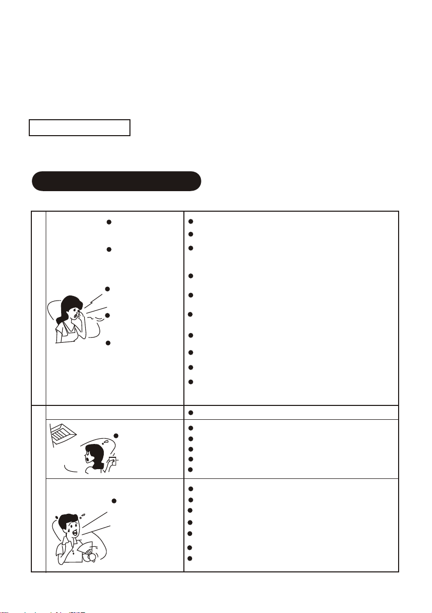
Malfunction & Handling Ways
Phenomenon following do not indicate any trouble
1.Usual protection
Protective function of compressor.
Compressor can not start within 3 minutes after it stops.
Cold air outlet prevention(In heating mode ).
The indoor fan cannot start if indoor heat exchanger can not reach certain temperature.
(1)Heating starts just now.
(2)Defrosting is going on.
(3)Heating in low temperature ( temperature is too low outside).
These are not failures

8
2.Defrosting
In heating mode, the outdoor heat exchanger may be frosted because the outside temperature is too
low. The frost cover may ill effect normal heating effect for AC. Thus, AC will automatically defrost
after heating mode is running for a while. In the process of defrostation, the compressor is running
with the indoor and outdoor fans stop.
3.Indoor unit emit water fog
When the relative humidity is too high in cooling or dehumidity mode,the unit may emit gas like fog
because of high relative humidityand great temperature drop.
When the AC return to heating after defrosting, water from defrosting may be evaporated and blown
out.
4.Noise
When air conditioner is in operation or stops, sound like flowing water occurs and begins louder after
2-3 minutes.
This is the sound comes form refrigerant flowing or condensed draining water.
When AC is in operaton or stops zizi sound occur due to little dilatability of heat exchange for
temperature changing.
5.ERRATIC SMELL from indoor uint
The indoor unit absorbs the odor of all the matters in the room and emits it in operation Cooling or
heating
( cooling type has no such function)converts into air flowing.
When the room temperature reaches the default value, the outdoor unit will automatically stop its
operation leaving air flowing only, thus, energy can be saved.
The outdoor unit will not restart until the room temperature rises (cooling mode) or lowers ( heating
mode) to some extent.
6.Condensation appears on the panel of the indoor unit
When it is overly humid in the room ( beyond 80%), startigcooling or drying mode may bring out
condensation around the air outlet of the panel.
1. Please do the following job well if the air conditioner is not used for a long time.
In order to dry the unit completely, set the FAN mode and run for 3-4hours.
Shut down the air conditioner and cut off the power supply.
ÖÆÈÈÄÜÁ¦ÖÆÈÈÄÜÁ¦
ÊÒÍâζÈÊÒÍâζÈ
¸ß
µÍ
¸ß
µÍ
¸ß µÍ¸ß µÍ
Outside Temp.
Heating Capacity
Low
High
High
7.Air outlet temperatureof HEAT mode is not comfortable.
Air conditioner absorbscaloric from outdoor and releases
to indoor inorder to heat up the room air during heating
process. This is the principlethat the heat pump works.
Heating absorption decreaseswhen the external
temperature is reduce.Its heating ability is therefore
lower (refers tothe right diagram). At the same time,
temperature difference of indoor &outdoorstrengthens
and then theheating charges is heavier.If the air
conditioner operation cannot attain a satisfactoryresult,
We suggest that you canuse other heatingdevice for
assistant.
Maintenance
No running
Whether power fail;
whether manual switch is on;
whether the fuse breaks;
whether the protector starts
whether setting time of "TIMER"approach
Whether air inlet or outlet of outdoor unit is blocked
Cooling&heating
effect is notgood.
Begin defrosting andstop fan motor running
Electromagnetic valve makesounds while defrostingbegins or end
When air conditioneris in operationor stops, soundlike flowing
water occurs andbegins louder after2-3minutes. This isthe sound
comes from refrigerantflowing or condenseddraining water.
When air conditioner isin operation or stop,sound occur due to
little dilatability ofheat exchange fortemperature changing.
Dust from wallcarpet ,clothes, cigarette,cosmetic, etc attachedon
the air conditioner.
Switch on thepower supply afterpower failure, runninglamp is
flashing
It does notrun in themode of coolingdue to otherindoor units in
the mode ofheating
When the setmode is contraryto default mode(heating)
Fan stops for preventingcool air blows out.
When used asmulti-drive unit, indicatorlamp flashing andrunning
stop.
Whether use TIMERON button withoutintention
Auto stop orauto start
Whether door orwindows are open
Whether the filter isaccumulated by dust
Whether the position ofloaver is proper;
Whether FANmode is settoo low orwhether. MODEis set to END
Whether the temperatureis set properly.
If choose theCOOL and HEAT at the same time.
White fog orwater
appear.
Zizi sound oftenoccur
Bad smell
Running lamp flashing
Non priority orwaiting
lamp flashs
TROUBLE SHOOTINGTROUBLE SHOOTING
Please refer to the following table before declaring repair service.
9
2. When used again after the unit stops for a long period:
When cleaning the filter and indoor unit, you must stop the unit and cut off power supply. Wipe the
indoor unit with soft cloth. It is forbidden to posh the machine with petrol, benzene, lye, powder,
detergent, insecticide etc., Which will damage the unit.
Ensure air in let and outlet of indoor and outdoor unit are not blocked by rubbish.
Check whether the grounded wire is loose and flexible, then connect the power.
When your air conditioner can not run in order, please shut down the machine and cut off the power
supply immediately. Then contact dealers.
After-salesservice
10
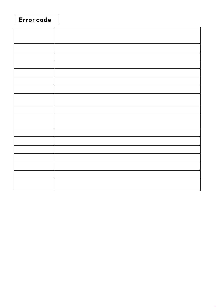
The display content
of indoor LED The definition of failure or protection
The indoor-outdoor communication goes wrong.
E0
The Room Temperature Sensor T1 goes wrong.
E1
The Internal Coil Temperature sensor T2 goes wrong.
The External Temperature Sensor T3 goes wrong.
The outdoor unit goes wrong.
The model configuration processing goes wrong.
The indoor fan goes wrong and/or the communication between the
indoor DC fan and the indoor main control panel goes wrong.
The Outdoor Temperature Sensor T4 goes wrong.
The exhaust temperature sensor (TP1 of variable-frequency
compressor) goes wrong
The variable-frequency module goes wrong.
The outdoor communication goes wrong.
The EEPROM goes wrong (The E2 of the outdoor unit goes wrong).
E3
E2
E4
E8
E7
E9
E5
E6
EC
EE
The outdoor fan goes wrong.
The EEPROM of main control panel goes wrong.
Water full protection
Ed
EF
d3
C5 The communication between the indoor unit and the wire controller
goes wrong.

11
Outdoor unit protection
Exhaust high-temperature protection (Variable-frequency
compressor or Slave F3)
Under-cooling protection in the cooling mode (Indoor unit coil
temperature protection)
Over-heating protection in the cooling mode (Condenser
high-temperature protection)
Over-heating protection in the heating mode (Indoor unit coil
temperature protection)
Outdoor high/low-temperature protection
P3
P7
P6
P4
P5
P8
P9
PA
PH
PC
H1
H2
H6
HE
Drive protection (load abnormal)
The modes conflict and the top air-out board communication goes wrong.
Exhaust temperature sensor failure protection of outdoor unit
Coil temperature sensor failure protection of outdoor unit
High pressure switch protection
Low pressure switch protection
Insufficient of refrigerant protection
Phase sequence protection
The display content
of indoor LED
Module protection
Over/Under-voltage protection
Over-current protection (Variable-frequency compressor)
P2
P1
P0
The definition of failure or protection

12
PREPARATION BEFORE INSTALLATIONPREPARATION BEFORE INSTALLATION
INSTALLATION
Refrigerant Pipe
Air purging
Be sure ofmachine type and name to avoid wrong installation.
Refrigerant pipe diameter must comply withthe prescription.
Refrigerant pipe mustbe heat-insulated.
Vacuum pump or refrigerantjar should be used in air purging of the connection pipe or
refrigerant can beused at the gas side.
INSTALLATION
Please go throughall the IMPORTANT SAFETY INFORMATION before installation.
Please install accordingto the installation manual.
Please read thelable on the machine carefully before installation.
WARNING
Users must engagedealer or authorized specialist for installation.
Any structure modificationmust comply with specific construction standard.
The unit mustbe hung over ceilings that can bear its weight.
Power cord thatis prescribed or complied with the requirement should beused.
All the electricmanipulation should be done by authorized specialists according tocurrent
specification or thisinstallation manual.
Please do notconnect electric supply before installation is finished.
Please assure goodventilation when refrigerant leaks to prevent its density goingbeyond
safety standard.
After the airconditioner is finished, please explain to the user aboutright ways of usage
and maintenance .Besides, ask the user to read and keep themanual carefully.
Keep away fromplace with volatile oil ( including engine oil) orvitriolic mist, otherwise, the
inner component willbedamaged with the performance greatly impaired.
Dimension of thefuse must be no less than the prescribed capacity.
Make sure aearth wire is installed.
Make sure anearthing breaker is installed.
If this airconditioner is installed on the mental part of architecture,electric installation must
be done inaccordance with concerning technology standard.
NOTICE
Important safety information
Key points of inspection

Choose the electric capacity and circuit according to the design manual. The diameter of the electric
supply line must be more than that of ordinary electromotor.
The refrigerant charge volume is based on 5m connecting pipe. If the connecting length is longer than
5m,please refer to the followings.
please keep record of additional refrigerant charge, pipe length and height drop of indoor&outdoorunit
( stick inside right panel)
Charge additional refrigerant
Electric wiring
Connect the electricsupply after air is vacuumed.
Wiring Specification
13
Under ceiling
Floor console
INDOOR UNIT INSTALLATION
°²×°¿Õ¼ä
Outlet
Outlet
Outlet
right
Please remove the grille and the side board.
Grille
Side board
Side board
Ensure sufficient space for installation and repair.
GENERAL: This INSTALLATION INSTRUCTION SHEET briefly outlines where and how to install
the air conditioning system. Please read over the entire set of instructions for the indoor and
outdoor units and make sure all accessory parts listed are with the system before beginning.
Installation Space
1.A place where there are sufficient space for repair.
2.Hung ceiling that can bear the weight of the machine.
3.A place without air inlet and outlet is not hindered and without influence from outdoor air.
4.A place without heat source like smoke, fire or toxic pullution.
5.A place where air flow can be transmitted everywhere in the room.
6.A place convienient for installation.
Choose installation location
Installation procedure
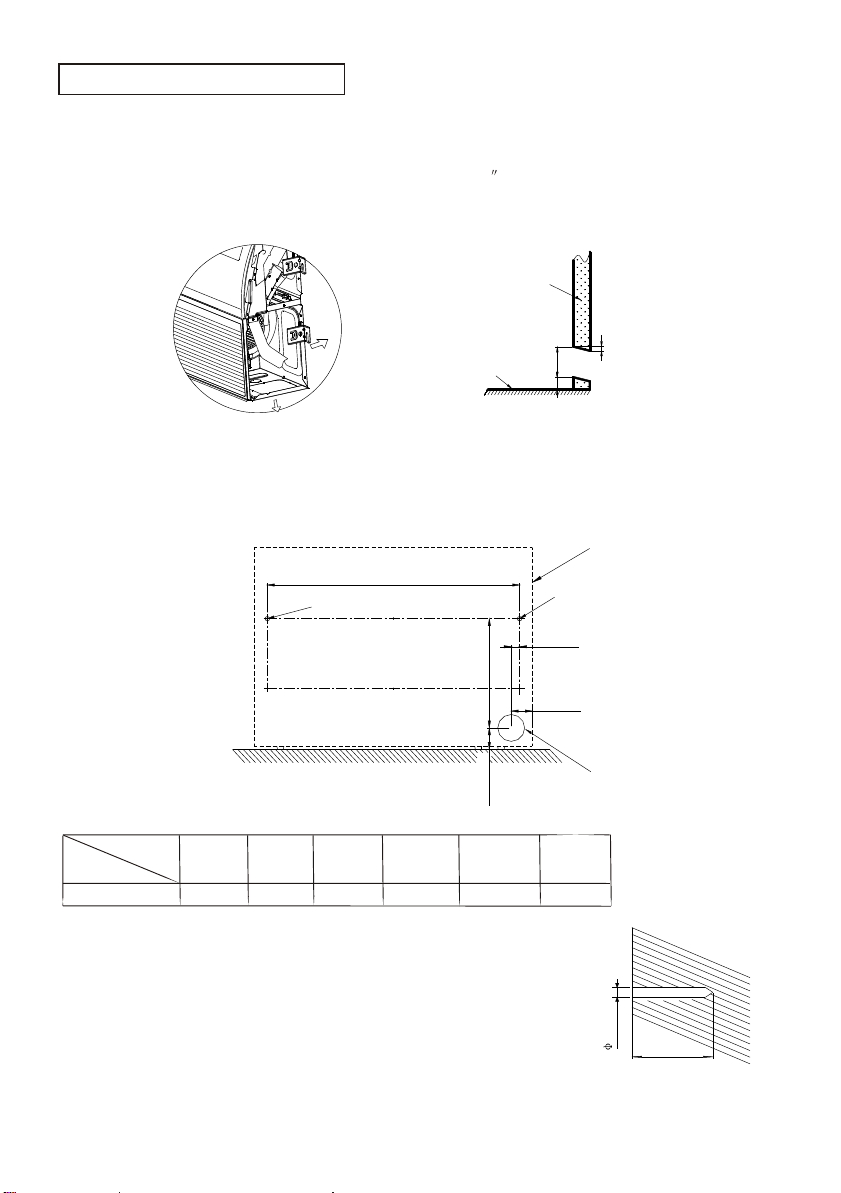
FLOOR CONSOLE TYPE
14
1.Select the piping and drainage directions.
The piping anddrain can be made in two directions as shown below(fig.1).
When the directionis selected,please drill a 100mm(4 )diameter hole onthe wall,and the
hole must betilted downward towards the outdoor for smooth water flow.When the pipeis
led out fromthe rear,make a hole in figure,at the position shown(fig.2).
100mm
30mm
10mm
Wall
Floor
Indoor
side
Outdoor
side
2.Drilling holes for anchor bolts and installing the anchor blots(m10)
According to theposition of the hole, install two expansible anchor bolts(Aand B) atthe
position shown inthe figure.
NOTE:
80mm
80mm
L
240mm
31mm
A(Anchor bolt)
B(Anchor bolt)
The 100mm
diameter hole
Outline of
the unit
Wall
10mm
About 55mm
With a concretedrill, drill two 10mm diameter holes at the position(A
and B) on the wall.
(Fig.1) (Fig.2)
Dimension
Coolling
Capacity 18K 24K 36K 48K
L
980mm 980mm 1200mm 1560mm
55K
1560mm
60K
1560mm
15
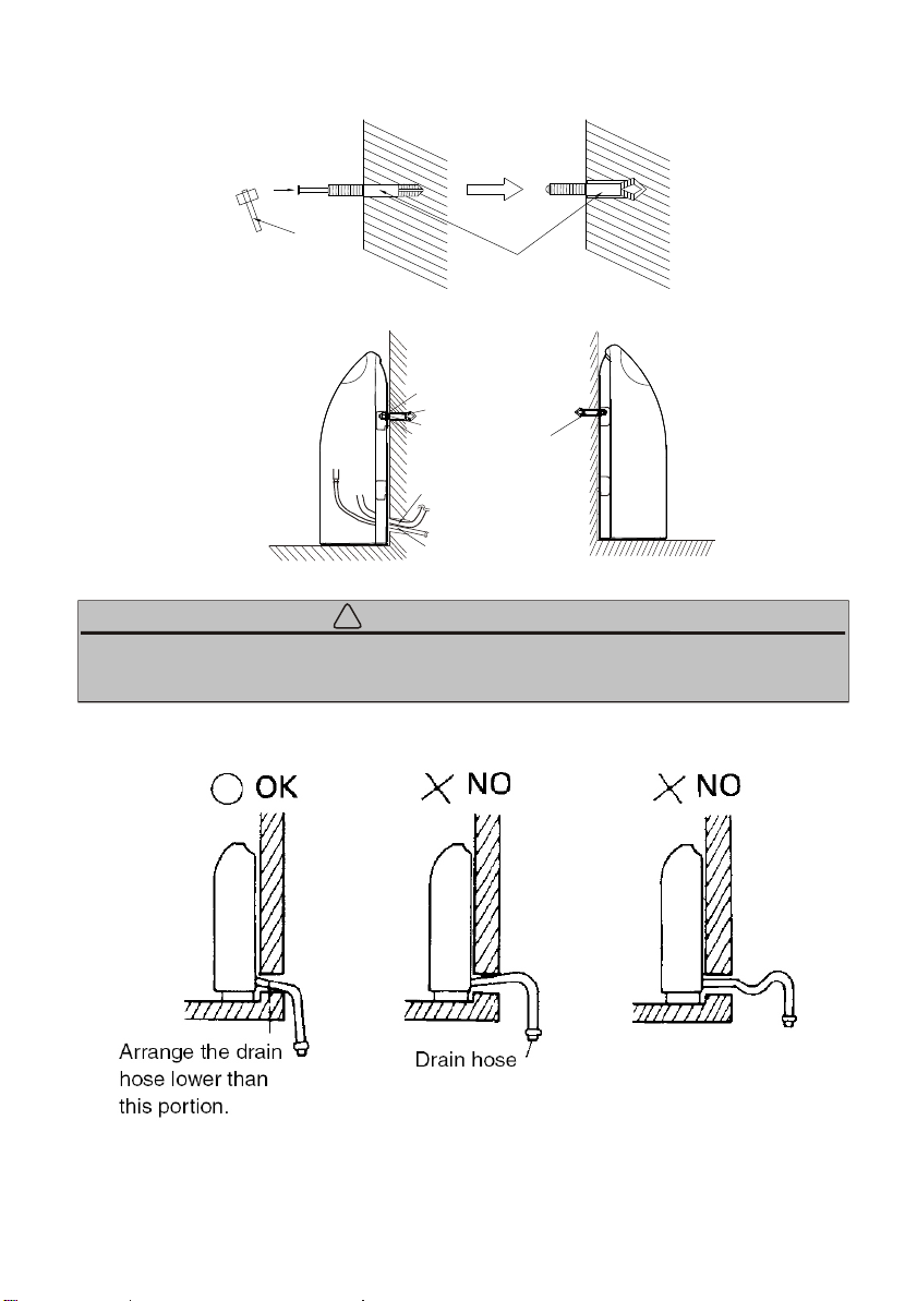
Insert the anchorbolts into the drilled holes, and drive the pins completely
into the anchorbolts with a hammer.
Hammer
Anchor bolts
(M10)
Install the unitto them with nuts,washers and spring washers
NOTE: The installationangle should notexceed 15 degrees.
CAUTION
Right
Drain pipe
Refrigeration
connection pipe
To outdoor unit
Nut
Washer
Spring washer
Bolt A
Left
Bolt B
!
Be sure toarrange the drain hose so that it is leveled lower than the drain hose connecting
port of theindoor unit.

CAUTION: Install the drainage hose at the rear,it should not be installed on the top .
wall
indoor outdoor
side side
10mm
Please drill four holes for anchor bolts at the position A,B,C and D.
NOTE:
240
L
CEILING
WALL
Drilling position
for piping
Drilling position
for anchor bolt
240
16
Now,securely tighten nuts to each bolt with washers and spring washers.
NOTE: The installation angle should not exceed 10 degrees.
Mount the unit to the anchor bolts
2. Drilling holes for anchor bolts and installing the anchor blots(m10).
When the directions are selected, drill 80 mm (3-1/8") and 50 mm (2") or 150 mm (6") dia. hole on
the wall so that the hole is tilted downward toward the outdoor for smooth water flow.
UNDER CEILING TYPE
1.Select piping and drain directions.
3. Installing indoor unit
Dimension
Coolling
Capacity 18K 24K 36K 48K
L
980mm 980mm 1200mm 1560mm
55K
1560mm
60K
1560mm

DRAINAGE PIPE CONNECTION
17
OUTDOOR UNIT INSTALLATION
Remove the holecover.
Drain hose
OK NO
A.Check whether the drain pipe is unhindered and each joint is airproof.
B.Inject 2000ml water into the drain pan to test whether the water flows smoothly.
1.Installing the drain hose
2.Drainage test
Insert the drain hose into the drain pan, then secure the drain hose with a nylon fastener(we have
connected the drain hose to the drain pan in the factory,you just need connect the drain pipe.).
Wrap the insulation (drain hose) around the drain hose connection.
Be sure to arrange the drain hose so that it is leveled lower than the drain hose connecting port of
the indoor unit.
1.Choose installation location
1.1 Inspection
As soon as a unit is received ,it should be inspected for possible damage during transit .if
damage is evident ,the extent of the damage should be noted on the carrier's delivery receipt
.a separate request for in inspection by the carrier's agent should be made in writing .see
local distributor formore information.
Requirements for installing/servicingR410A Equipment.
Gauge sets ,hoses , refrigerant containers , and recovery system must be designed to
handle the POEor PVE type oils.
Manifold sets should be 800 PSIG high side and250PSIG low sidewith 550 PSIG low side
restart.
All hoses must have a 700 PSIG servicepressure rating.
Leak detectors should be designed to detect refrigerant.
Recovery equipment( including refrigerant recovery containers)must be specifically
designed to handleR410A.
A liquid-line filter drier is
Required on everyunit .
Do not use an R-22TXV.
See the Fig.1
LIQUID-LINEFILTER-DRIER
Fig.1Filter-Drierinsatllation
LARGESERVICEVALVE
SMALLSERVICEVALVE
1.2 Limitations
2.0 General
The unit shouldbe installed in accordance with all National, State and local safety Codes
and the limitationslisted below:
1.Limitations for theindoor unit, coil and appropriate accessories must also be observed.
2.The outdoor unitmust not be installed with any duct work in the air stream. The outdoor fan
is the propellertype and is not designed to operate against any additional external static
pressure.
3.The maximum andminimum conditions for operation must be observed to assure a system
that will givemaximum performances and minimum services.
4.This unit isnot designed to operate with a low ambient kit. Do not modify the control
system to operatewith any kind of low ambient kit.
5.The maximum allowableline length for this product is 166 feet (just for 48K/ 55/60K).
The outdoor unitsare designed to be connected to a matching indoor coil with sweat connect
lines .Sweat connectunits are factory charged with refrigerant for a matching indoor coil plus
25 feet offield supplied lines.
Matching indoor coilsare available with a thermostatic expansion value or an orifice for most
common usage. The orifice sizeand /or refrigerant charge may need to be changed for some
indoor-outdoor unit combinations,elevation differences or total line lengths.
18
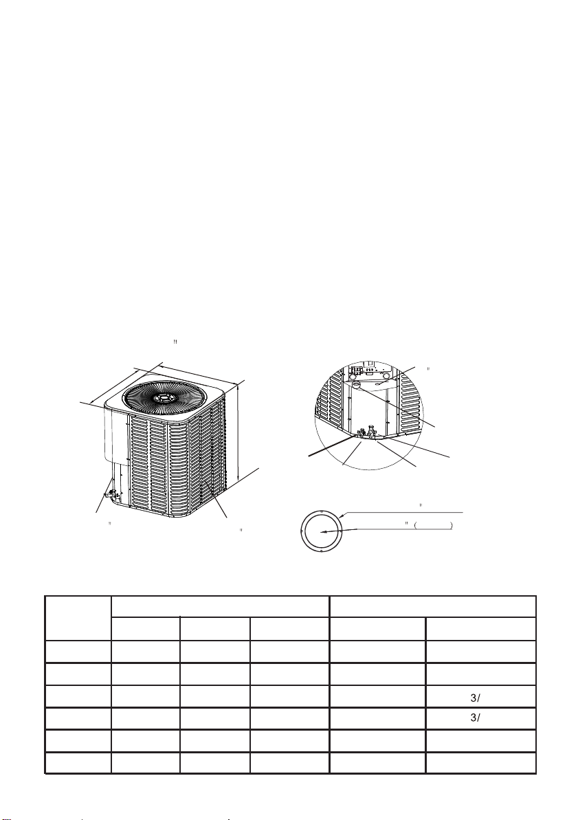
Air discharge: Allow 60 minimum clearance.
Note: grill appearance mayvary.
W
L
H
Air inlets: Louvered
panels allow 18
mimimum clearance
Service access:
Allow 24 clearance
Power wiring
see detail a
Control wiring
7/8 (22.2mm)
Service
fitting Liquid line
connection
Service
fitting
Vapor line
connection
Fig.2 Dimensions
Detail a
Hole 1-3/32 27.8mm
Knockout 1-11/32 (34.5mm)
Unit
Model(
Btu/h)
18K
24K
36K
48K
55K
3/8
24-15/16(633)
33-3/16(843)
33-3/16(843)
Vapor in.
Liquid in.
W(in.)(mm) L(in.)(mm)
H(in.)(mm)
Dimensions(Inches)
Refrigerant Connection Service Valve Size
3/8
3/8
3/8
3/8
24-15/16(633)
29-1/8(740)
29-1/8(740)
29-1/8(740)
21-7/8(554)
21-7/8(554)
29-1/8(740)
29-1/8(740)
29-1/8(740)
Dimensional data
5/8
4
5/85/85/8
23-5/8(600)
23-5/8(600)
33-3/16(843)
4
7/8
60K
33-3/16(843)
3/8
29-1/8(740)
29-1/8(740) 7/8

CAUTION
This system uses R410A refrigerant which operates at higher pressure than R-22. No
other refrigerant may be used in this system. Gauge sets, hoses, refrigerant
containers, and recovery system must be designed to handle R410A.If you are unsure,
consult the equipmentmanufacturer.
3.0 Unit installation
3.1 Location
Before starting theinstallation, select and check the suitability of the location for both the
indoor and outdoorunit. Observe all limitations and clearance requirements. The outdoor
unit must havesufficient clearance for air entrance to the condenser coil, for airdischarge
and for serviceaccess. See Fig.2
If the unitis to be installed on a hot sun exposed roof or a black-topped ground area, the
unit should beraised sufficiently above the roof or ground to avoid taking the accumulated
layer of hotair in to the outdoor unit.
Provide an adequatestructural support.
The unit maybe installed on a solid base that will not shift or settle, causing strain on the
refrigerant lines andpossible leaks. Maintain the clearances shown in Fig.2 and install the
unit in alevel position.
Normal operation soundlevels may be objectionable if the unit is placed directly under
windows of certainrooms(bedrooms, study, etc.)
Topof unit discharge area must be unrestricted for at least 60 inches above the unit.
3.2 Ground installation
Elevate the unitsufficiently to prevent any blockage of the air entrances by snow in areas
where there willbe snow accumulation. Check the local weather bureau for the expected
snow accumulation. Checkthe local weather bureau for the expected snow accumulation
in your area.Isolate the unit from rain gutters to avoid any possible wash out of the
foundation.
When installing units on a roof, the structure must be capable of supporting the
total weight of unit, including a padded frame unit, rails, etc. which should be
used to minimize the transmission of sound or vibration into the conditioned
space.
1.Provide a basein the pre-determined location.
2.Remove the shippingcarton and inspect for possible damage.
3.Compressor tie-down boltsshould remain tightened.
4.Position the uniton the base provided.
3.3 Roof installation
3.4 Unit placement
NOTE:For multiple unitinstallations, units mustbe spaced aminimum of
18 inches apart.(Coilface to coilface.)
The outdoor unitshould not beinstalled in anarea where mudor ice couldcause
personal injury.
WARNING
19
This manual suits for next models
6
Table of contents
Popular Inverter manuals by other brands

Silverline
Silverline 204757 manual

Grundfos
Grundfos CUE Safety instructions and other important information

Northern Lights
Northern Lights M864W and M864W3 Operator's manual

Ingeteam
Ingeteam INGECON SUN 1Play 3.68TL quick start guide

Champion
Champion 200977 quick start guide

Kostal
Kostal PIKO MP plus series Installation and operation manual


Tripp Lite
Tripp Lite PowerVerter PV700HF owner's manual

Delta
Delta RPI H3 110 Quick installation guide

Centech
Centech 60601 Owner's manual & safety instructions

Delta
Delta RPI M6A Quick installation guide

MQ Power
MQ Power Ultra-Silent DCA-150USJ Operation and parts manual

Blue Wave
Blue Wave NA4177 instructions