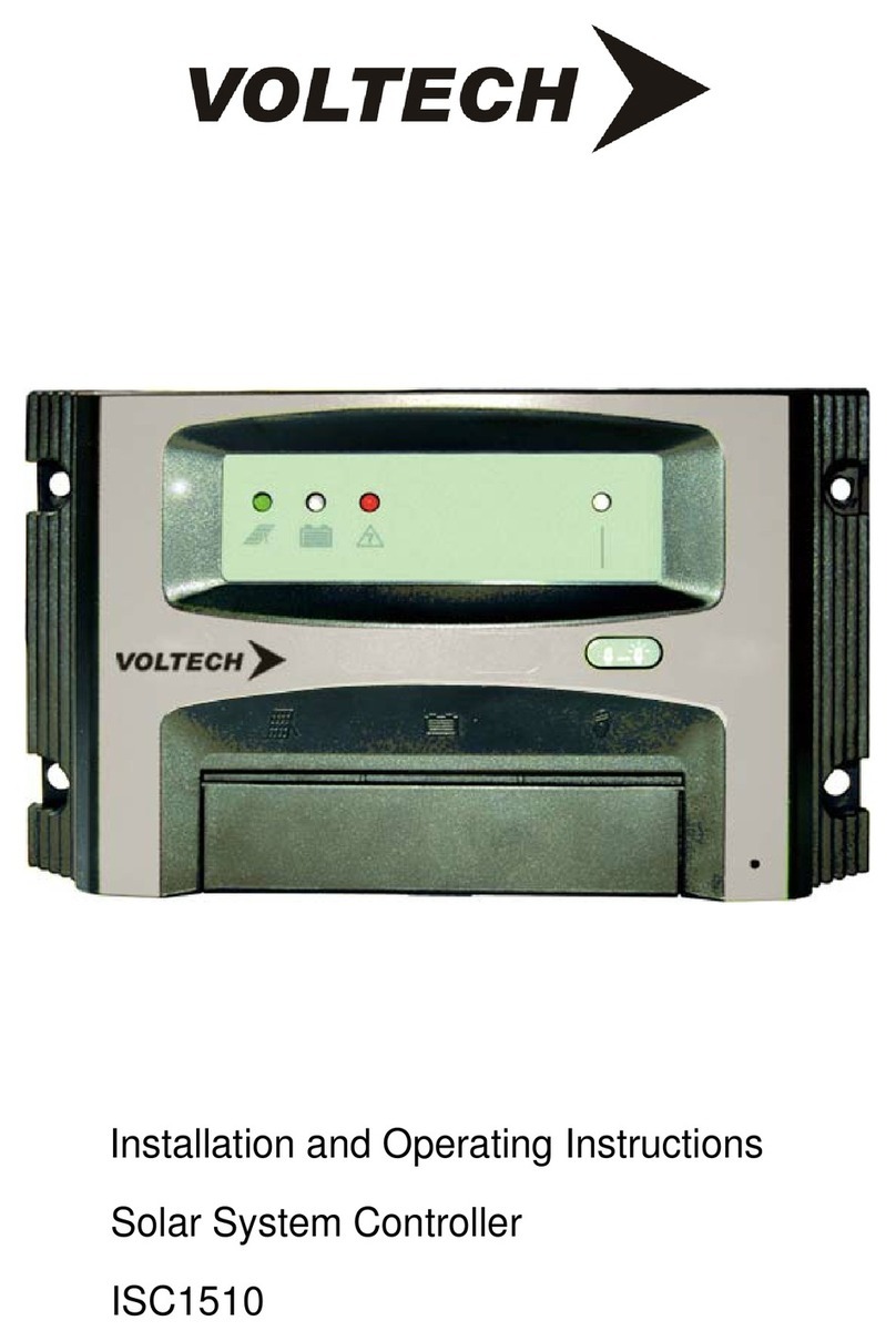
Voltech TS-300-12 User manual

Pure Sine Wave Inverter
OWNER’S MANUAL
DC-AC Power Inverter
Special Feature:
DC Fuse: Accessible n rear c ver.
1.5 times rated p wer f r 10 sec nds
2 times rated p wer f r 2 sec nds
Rem te C ntr l (Opti nal)
USB Output: 5V,500mA (Opti nal)
Variable speed DC fans, C ntr lled by: Temperature and L ad.
Pr tecti n: LED Indicat r& Audible Alarm.
12V r 24V M dels (Input v ltage range: -15% ~ +25%)
Output v ltage regulati n: ±10%
Output wavef rm: Pure Sine Wave
Frequency: 50Hz±1%
CE and R HS Appr ved
12 m nths warranty
Thank you for purchasing the Voltech Pure Sine Wave Inverter. Carefully read,
understand and comply with all instructions efore use.

2
Ta le of contents
1. Introduction………………………………………………..……3
1.1 What is an inverter?……………………………..….…..3
1.2 Pure Sine Wave Inverter……………………….……….3
2. Main Components………………………………………….…...3-6
2.1 Front panel………………………………………….…..3-4
2.2 Rear panel………………………………………..….…..5
3. How to Use Inverter….…………………………………….……6
3.1 Load consideration………………………..………….…6
3.2 Configuring the Battery Bank …………………………7
3.3 Battery wiring examples………………………..………7-8
3.4 Placement of the inverter………………………..……..8
3.5 Mounting position of the inverter………………...……9
3.6 Connections……...…………………………………..….9
4. Important Safety Instructions…………………….……………9-10
5. Protection Feature……………………………………………...10
6. Trou leshooting ………….……………………………..……...11-12
7. Specifications………..…………………………………….........13-14
8. Maintenance ……………………………………………..……..14
9. Warranty…………………………………………………..……14
Appendix I: Remote Control Switch…..……………………..…15
Appendix II: Recommend………….……………………….……16
Specifications are su ject to change without prior notice
E & OE
Version of Instruction manual 2.0

3
1. INTRODUCTION
1.1 What is an Inverter?
P wer inverter is an electr nic device that c nverts DC (Direct Current) battery p wer t standard
AC (Alternating Current) p wer. DC is the p wer that is st red by a battery while AC is the
standard p wer needed t run electrical equipment. A P wer Inverter can be used in places and
situati ns where AC p wer is n t available.
1.2 Pure Sine Wave Inverter
If y u want t run y ur equipment exactly t the manufacturer’s specificati ns,
ch se a pure sine wave inverter. With pure sine wave, m t rs start easier and run
c ler. As well, s me equipment may only perate pr perly with a pure sine wave
inverter, such as laser printers, variable speed m t rs and digital cl cks/devices.
2. MAIN COMPONENTS
2.1 Front Panel
The fr nt panel view sh ws the inverter’s ON/OFF Switch, AC Output
Receptacle, LED Indicat r Light, Vent Outlet, Rem te C ntr l p rt, Chassis
Gr und, USB.
A. ON/OFF Switch.
This switch c ntr ls ON/OFF perati n f the inverter.
B. LED Indicator Light:
a) Fault: Turns Red t sh w fault, reference t Tr ublesh ting
b)Inverter: This light will illuminate Green whenever c nnected equipment
has inverted AC p wer available at the utlet.

4
C. AC Output Receptacle: Australia (10Amp)
D. Vent Outlet.
All ws h t air pushed fr m the rear c ling fan t exit. Theref re it MUST be kept clear
whenever the p wer inverter is t be used.
E. Chassis Ground (s me m dels)
Pr perly gr unds the Inverter t vehicle gr unding system r t earth gr und.
G.
Remote Switch Port
(Optional):
Use t c nnect the rem te ON/OFF switch via a c mmunicati n cable.
H. Hardwire Terminal Block
(2500W to 6000W):
N te: When the l ad current is >10A (2300W) Y u must use the utput terminal c nnecti n which
can be f und inside the AC utput panel f the inverter.
Ensure the inverter is turned off & DC input is disconnected before opening the cover to
connect the Hard Wire option.
Seek pr fessi nal assistance if y u are unfamiliar with electrical wiring.
Check with l cal auth rities as regulati ns may apply.
I. USB Port (Optional):
USB P rt pr vides p wer t perate and charge USB-enabled devices.

5
2.2 Rear Panel
The rear panel view sh ws the inverter’s C ling fan, DC Battery Terminals,
Fuses, Chassis Gr und (s me m dels).
A. Temperature and Load controlled Multi-Speed Cooling Fan
Quiet, efficient fan pr l ngs equipment service life.
1. L ad <40% r inner temperature less than 30 ℃, = fan(s) don’t run.
2. L ad >40% t <60% = the fan’s r tati nal speed is 40%
3. L ad >60% t <80%, = the fan’s r tati nal speed is 60%
4. L ad >80% t <100% = the fan’s r tati nal speed is 80%
5. L ad @100% = the fan’s r tati nal speed is 100%
6.Once Inner temperature is m re than 45℃, the fan’s r tati nal speed is 100%.
B. DC Battery Terminals
C nnect the inverter t battery r ther p wer s urces.
Negative (-) and P sitive (+) DC terminals sh uld be kept insulated t pr tect
fr m accidental sh rt circuits.
a) C nnect the red cable t the red p st marked (+) n the back f the
inverter. C nnect the ther end t the p sitive terminal n the battery
b) C nnect the black cable t the black p st marked (-) n the back f the
inverter. C nnect the ther end t the negative terminal n the battery.
If y u c nnect the cables t the inc rrect terminals, y u will reverse the
p larity and damage the inverter.
PROHIBITED: REVERSE POLARITY.
DAMAGE CAUSED BY REVERSE POLARITY WILL NOT BE
COVERED BY WARRANTY.

6
C. Fuse
Fuses f r DC Input have been fitted t the rear panel. S as t be easily accessible in
rder t facilitate checking & replacing if required. Depending n the installati n this
maybe p ssible with ut rem ving the inverter.
3. HOW TO USE INVERTER
3.1 Load consideration
When an appliance with a m t r starts, it requires a m mentary surge f p wer. This
surge f p wer is the “starting l ad” r “peak l ad”. Once started, the appliance
requires less p wer t c ntinue t perate. This is kn wn as the “c ntinu us l ad”. It
is imp rtant t kn w the starting l ads and the c ntinu us l ads f the appliances that
are t be p wered by the inverter.
Appliance p wer is rated in watts. This inf rmati n is usually stamped r printed n
m st appliances and equipment. In s me cases, a t l will be rated in amperes. T
c nvert fr m amps t watts, multiply:
Amps x AC v ltage = Watts (Eg: 2.0 A x 230 V = 460 Watts)
This f rmula yields an appr ximati n f the c ntinu us wattage l ad f that
appliance.
The startup l ad f an appliance is a maj r fact r f whether this inverter can p wer
it.
Startup l ad is m mentary. With many appliances, it is appr ximately twice the
c ntinu us l ad, but s me appliance startup l ads can be as high as eight times the
c ntinu us l ad.
If y u are unsure f y ur equipments P wer requirements an ‘Energy use’ meter may
be used t measure the starting peak & continuous wattage .
In rder t less n the p ssibility f damaging the inverter r the equipment.
This inverter will aut matically shut d wn in the event f an utput verl ad,
When this ccurs a Red LED indicat r will turn n and the Buzzer signals a fault.

7
3.2 Configuring the Battery Bank
T determine the approx’ minimum battery amp-h ur rating that y u will need t
perate appliances fr m the inverter and any DC appliances p wered by the battery
bank, f ll w these steps:
1. List the maximum c ntinu us wattage that the inverter has t supply.
2. Estimate the number f h urs the appliances will be in use between battery
recharges. This will vary depending n appliances. F r example, a typical h me-use
c ffee maker draws 500 watts during its brew time f 5 minutes. It maintains the
temperature f the p t, requiring 100 watts. Typical use f a micr wave ven is nly
f r a few minutes. S me l nger perating time appliances are lamps, TVs, c mputers
and refrigerat r/freezers.
Determine the t tal watt-h urs f energy needed. This is d ne by multiplying average
p wer c nsumpti n in watts by h urs f run time. F r example: 500 watts f r 10
h urs = 5000 watt h urs. T get an estimate f the maximum current (in amps) that a
battery bank must be capable f delivering t the inverter, divide the l ad watts by ten.
F r example a 500 watt appliance l ad will need 50 amps at 12 v lts DC. Using the
500 watts ( r 50 amps) f r 10 h urs example as ab ve, then 50 amps is needed f r 10
h urs. This pr vides us with the basic amp-h urs (AH) f battery that is required. Ten
h urs at 50 amps equals 500 amp-h urs (AH). There are additi nal fact rs that
determine actual run time.
These include:
•
AC appliance l ad and time in use (basic AH).
• Cable gauge and length (cable l sses).
• Charge level f the batteries (between use, chargers have t be able t fully charge the batteries).
• Temperature f the batteries (c lder batteries pr vide fewer amps).
• Age and c nditi n f the batteries ( lder batteries l se AH capacity).
• C mpliance with turning ff unnecessary AC l ads.
• Use f DC appliances and c mpliance with turning ff unnecessary DC l ads.
3.3 Battery Wiring Examples
In renewable energy systems, batteries are c nnected t each ther in ne f three ways:
• Series (v ltage increases, amperage stays the same as a single battery)
• Parallel (v ltage stays the same as a single battery, amperage increases)
• Series/Parallel (b th v ltage and amperage increase)

8
3.4 Placement of inverter
The l cati n where t install inverter must be:
A. DRY: D n t all w water t drip r splash nt it.
B. COOL: Ambient air temperature sh uld be between 0º C and 40º C - ideally between 15º C and
25º.D n t place the inverter n r near a heating vent r any piece f equipment which is
generating heat ab ve r m temperature. D n t place the inverter in direct sunlight
unnecessarily.
C. VENTILATED: All w at least ne inch f clearance ar und the unit f r air fl w. D n t place
items n r ver the inverter during perati n. Make sure that air is all wed t circulate freely
ar und the unit. A fan is helpful in the case where the inverter is perating at maximum
D. SAFE: D n t install the inverter in the same c mpartment as the batteries r in any
c mpartment where flammable liquids r fumes may be r may bec me present.
E. DUST: D n t install the inverter in a dusty envir nments. The dust can be drawn int the
unit when the c ling fan is w rking.
F. CLOSE TO BATTERIES: Av id excessive cable lengths. D n t install the inverter in the same
c mpartment as batteries.

9
3.5 Mounting position of the inverter
The inverter may be m unted n a h riz ntal r vertical service. Away fr m heat sensitive
materials & flammable items. (F ll w All Safety Instructi ns).
3.6 Connections
F ll w the c nnecti n sequence described bel w.
Step 1: Ensure that the ON/OFF switch n the Inverter is in the OFF p siti n. If the
p wer s urce is a DC p wer supply, switch it OFF as well.
Step 2: C nnect inverter t p wer s urce.
C nnect the DC cables t the DC battery terminals n the rear panel f the inverter.
The red
terminal is
p sitive (+)
and the black terminal is negative
(-). (See Page 5, 2.2B )
Step 3: C nnect inverter t appliances.
Make sure the l ad p wer within the rated p wer f inverter and the start p wer sh uld n t
exceed the peak p wer f the inverter.
Step 4: Turn n the inverter 1st, then turn n the appliance y u want t run.
If y u are perating several l ads fr m the p wer inverter, turn them n separately after the
inverter has been turned n. This will ensure that the p wer inverter d es n t have t deliver the
starting currents f r all the l ads at nce.
4. IMPORTANT SAFETY INSTRUCTIONS
Inc rrect installati n and misuse f the inverter may result in danger t the user r hazard us
c nditi ns.
1. D n t attempt t c nnect the utput t any ther p wer s urce, including any AC mains.
2. Make sure the pening t the ventilati n fan and vent h les are n t bl cked.
3. Av id pulling n the c rds and cables. Always grip plugs firmly when unplugging fr m
p wer s urce and when disc nnecting cables.
4. T av id electrical hazard, be sure t unplug the inverter fr m its external p wer s urce
bef re inserting the AC plug.
5. F r ind r use nly. Av id exp sure t external heat s urces including direct/pr l nged
sunlight, dust, c rr sive chemicals and m isture.
6. It is n rmal f r inverters t bec me warm during use. Av id t uching the device during use
r p siti ning near heat-sensitive materials.
7. D n t dr p r subject the inverter t undue sh ck.
8. D n t place anything n t p f the inverter.
9. The use f impr per cables, c nnect rs, r access ries n t supplied with this pr duct
c nstitutes misuse and may result in injury r damage.
10. D n t attempt t service r dissemble. The unit is n t user-serviceable. Attempting t
disassemble r service the unit can result in electrical hazard, including death fr m
High-V ltage electric sh ck! If y u experience pr blems with the unit, disc ntinue use and
c ntact a c mpetent Technician r the riginal place f purchase.
11. When cleaning the inverter, please switch ff p wer & unplug the inverter. Carefully clean
with a dry cl th. D n t use wet cl th r cleanser.

10
12. Disc nnect all AC and DC c nnecti ns bef re w rking n any circuits ass ciated with the
inverter. Turning the ON/OFF switch n the inverter t ff p siti n may n t entirely rem ve
danger us v ltage.
13. Keep the Inverter,Batteries & all cabling away fr m children.
5. PROTECTION FEATURE
This Inverter is equipped with numer us pr tecti n features t ensure safe perati n.
Input Low Voltage Protection:
A: When battery v ltage is bel w 10.8V±0.2V(f r 12V input inverter)/21.6V±0.4V(f r 24V
input inverter)/ 43.2V±0.8V(f r 48V input inverter) The
Buzzer will sound 2 times and
RED LED will link 2 times every eight seconds
, which indicates DC p wer supply
v ltage is descending and batteries need t recharge.
B: When input v ltage is bel w 10.2V±0.2V(f r 12V input inverter)/20.4V±0.4V(f r 24V input
inverter)/ 40.8V±0.8V(f r 48V input inverter),The
Buzzer will sound 3 times and RED
LED will link 3 times every eight seconds
; AC utput will be aut matically shut ff.
Input Over Voltage Protection
When input v ltage reach 15.5V±0.2V (f r 12V input inverter)/31V±0.4V (f r 24V input
inverter)/62V±0.8V (f r 48V input inverter),The
Buzzer will sound 4 times and RED
LED will link 4 times every eight seconds
; the AC utput will be shut ff aut matically.
Short Circuit Protection
When sh rt circuits ccur, RED LED constantly flashing; AC utput will be shut ff.
Overload Protection
When verl ads ccur, RED LED constantly flashing,: AC utput will be shut ff.
Reverse polarity protection: Fuse and/or MOSfet
a. via Fuse: When battery terminals are reverse c nnected, fuse(s) will be bl wn t pr tect
appliances.
b.via MOSfet(Opti nal): When battery terminals are reverse c nnected, the inverter w n’t w rk
until the fault is c rrected.
Over Temperature Protection
When heat sink temperature exceeds 45ºC, the inner c ling fan will aut matically turn n t c l
the inverter; when Temp dr ps t less than 30ºC,the inner c ling fan will aut matically shut ff.
When inner temperature exceeds 75ºC, The
Buzzer will sound 5 times and RED LED
will link 5 times every eight seconds
; AC utput will aut matically shut ff.

11
6. TROUBLESHOOTING
.
TV Interference
Y u can s metimes get interference n TV & Radi receivers. This may be impr ved
thr ugh use f a filter(s) but m st pr blems ccur because f Weak Signal t the TV.
On s me ccasi ns when there is interference n every stati n, y u can try the
f ll wing:
Place the inverter farther fr m the TV and TV antenna and cable.
Make sure the Inverter Casing is gr unded t the Vehicle Gr und(Chassis)
Try t change the directi n f TV signals cable and TV antenna t reduce the
interference t minimum.
Use screened antenna cable f higher quality.
SYMPTOM POSSIBLE CAUSE SOLUTIONS
ON/OFF switch is switched on,
ED does not light. Buzzer is
off. There is no AC voltage
There is no voltage at the DC
input Terminals
1. Check the continuity of the
battery input circuit
2. Check that the battery fuse is
intact. Replace if blown
3. Check that all connections in
the battery input circuit are tight
Polarity of the input voltage has
been reversed that has blown the
DC side fuses.
( Note: Reverse polarity may
cause perma e t damage)
Correct the polarity of the input
connections and replace the
fuse.
If the unit does not work after
replacing the fuse, the unit has
been permanently damaged
Call Tech ical Support
Buzzer alarm is sounded 1
time. There is no AC voltage.
1. oose AC output connections.
2.Short circuit of AC Output
wiring.
1.Tighten AC output connections
2.Check AC wiring for short
circuit.
Buzzer sounds 2 times
and Red LED links 2
times every eight
seconds
V ltage at the DC input
terminals reads bel w;
10.8±0.2VDC(12V versi n),
21.6±0.4VDC(24V versi n),
43.2±0.8VDC(48V versi n).
1.Check that the battery is fully
charged. Recharge if low.
2. Check that the battery cables
are thick enough to carry the
required current over the
required length. Use
thicker cables if required.
3. Tighten connections of the
battery input circuit

12
Buzzer sounds 3 times
and Red LED links 3
times every eight
seconds
V ltage at the DC input
terminals reads bel w;
10.2±0.2VDC(12V versi n)
20.4±0.4VDC(24V versi n)
40.8±0.8VDC(48V versi n)
1.Check that the battery is fully
charged. Recharge, if low
2. Check that the battery cables
are thick enough to carry the
required current over the
required length. Use thicker
cables, if required
3. Tighten connections of the
battery input circuit
.
Buzzer sounds 4 times
and Red LED links 4
times every eight
seconds
Higher input DC voltage than
15.5±0.2VDC(12V versi n),
31±0.4VDC(24V versi n),
62±0.8VDC(48V versi n)
1. Check that the voltage at the
DC input terminals is more than
15V/30V/60V DC.
2. Ensure that the maximum
charging voltage of the battery
charger /alternator / solar
charge controller is below 15
V/30V/60VDC
3. Ensure that an un-regulated
solar panel or wind turbine is not
used to charge a battery
Buzzer sounds 5 times
and Red LED links 5
times every eight
seconds
System overheating
1. Check that the fan is working.
If not, the fan / fan control circuit
may be defective Call Tech ical
Support
2. If the fan is working, check
that the ventilation slots on the
suction side and the openings
on the discharge side of the fan
are not obstructed
3. If the fan is working and the
openings are not obstructed,
check that enough cool
replacement air is available.
Also check that the ambient air
temperature is less than 45º C
4. Reduce the load to reduce the
heating effect
5. After the cause of overheating
is removed and the unit cools
down, it will reset automatically
Red LED c nstantly flashing
The loads is 200% higher than
rated power.
1. Disconnect the load
2. Reduce the load
3.Cool the unit.

13
7. SPECIFICATIONS – (KS models are not availa le)
Item Model
TS-300-12/24 KS500P KS600P TS-800-12/24 TS-1500-12/24 KS2000P
O
U
T
P
U
T
Rated P wer
300W 500W 600W 800W 1500W 2000W
Surge P wer
120%<L ad<150% Rated p wer f r 10s,150%<L ad<200% Rated p wer f r 2s
AC V ltage
100V/110V/115V/120Vac r 220V/230V/240Vac
AC utput regulati n: 10%
Frequency:50Hz±1%
Wavef rm
Pure Sine Wave(THD<3%) at rated input v ltage
Pr tecti n
AC sh rt circuit, Overl ad, Over temperature
I
N
P
U
T
Bat. V ltage Range
10.8V-15.5V(12V versi n) 21.6V-31V(24V versi n) 43.2V-62V(48V versi n)
Efficiency
M re than 85%
Pr tecti n
Battery L w Alarm, Battery L w Shutd wn, Battery P larity Reverse by Fuse
Battery Types
Open & sealed lead acid battery
Dimensi n((L*W*H)cm
17*15*5.5 21*15*7 21*15*7 37.5*15*7.2
36*22*9 29*22*9
Packing
PCS/CTN
12 6 6 4
2 2
KGS/CTN
16.5 14.5 15.5 14.5
11.5 13.5
MEAS(L*W*H)cm
44*42*32 42*34*45 42*34*45 45*34*42
45*31*38 45*31*38
Item Model
TS-2500-12/24 KS3000P KS4000P KS5000P KS600P
O
U
T
P
U
T
Rated P wer
2500W 3000W 4000W 5000W 6000W
Surge P wer
120%<L ad<150% Rated p wer f r 10s
150%<L ad<200% Rated p wer f r 2s
AC V ltage
100V/110V/115V/120Vac r 220V/230V/240Vac
AC utput regulati n: 10%
Frequency:50Hz±1%
Wavef rm
Pure Sine Wave(THD<3%) at rated input v ltage
Pr tecti n
AC sh rt circuit, Overl ad, Over temperature
I
N
P
U
T
Bat. V ltage Range
10.8V-15.5V(12V versi n) 21.6V-31V(24V versi n) 43.2V-62V(48V versi n)
Efficiency
M re than 85%
Pr tecti n
Battery L w Alarm, Battery L w Shutd wn, Battery P larity Reverse by Fuse
Battery Types
Open & sealed lead acid battery

14
Dimensi n((L*W*H)cm
44.5*22*9 36*22*15 41*22*15 36*22*15 36*22*15
Packing
PCS/CTN
2 1 1 1 1
KGS/CTN
15 10.5 11.5 14.5 15
MEAS(L*W*H)cm
50*32*36 56*35*26 56*35*26 67*34*24 67*34*24
AC Out Receptacle USA, UK, Germany, France, Australia, Brazil, Italy, S uth Africa, etc.
C ling Temperature and L ad C ntr lled
Envir nment
Operating Temperature -15 ° C t 40° C
St rage Temperature -40 t 85°C
Relative Humidity 20% ~ 90% RH n n-c ndensing
N te: *
The specificati ns are subject t change with ut pri r n tice f r further
impr vement f pr ducts.
8. MAINTENANCE
T keep y ur inverter perating pr perly, there is very little maintenance required.
Y u sh uld clean the exteri r peri dically with a dry cl th t prevent accumulati n f
dust and dirt. At the same time, tighten the screws n the DC input terminals.
9. WARRANTY
We guarantee this pr duct against defects in materials and w rkmanship f r a peri d
f 12 m nths fr m the date f retail purchase by end user.
This warranty will be c nsidered v id if the unit has been misused, altered, r
accidentally damaged. We are n t liable f r anything that ccurs as a result f the
user’s fault.
If the warranty peri d f r y ur pr duct has expired r the unit was damaged by
misuse r inc rrect installati n r if ther c nditi ns f the warranty have n t been
met, r if n dated pr f f purchase is available then C sts t repair y ur unit may
be applicable.
FOR TECHNICAL ADVICE OR HELP PLEASE CONTACT:
PH: 07 3219 6655
FAX: 07 3219 6644
EMAIL:supp rt@electr parts.c m.au
WEB: www.electr parts.c m.au

15
Appendix I: Rem te C ntr l
Remote Control Switch
●
Power ON/OFF Switch
P wer ON/OFF switch is t turn the inverter n r ff.
●
Battery Capacity/Load Voltage indicator
Load: Sl w flash, 1time per sec nd. Sh w the appr ximate c nnected equipment l ad level. Five
Levels---20%,40%,60%,80%,100%.
Battery: S lid green. Sh w the battery residual capacity.
Five Levels---20%,40%,60%,80%,100%.
Transfer time(Between L ad and battery ): Every 8sec nds
●
Stand y/AC ON Indicator
Stand y: Sl w flash, l ad p wer is less than 5% f rated p wer r standby.
AC ON: S lid green. Inverter’s utput is c ntinu us.
●
Fault: Turns red t sh w fault, refer t Tr ublesh ting f Inverter Manual.
Connecting the Communications Ca le
The c mmunicati ns cable is 3meters, 6-c nduct r cable (wired like a n rmal teleph ne-type
cable). This cable is c nnected t the RJ11 jack n the rear f the rem te c ntr l and t the
REMOTE p rt l cated n the rear f the inverter.
Notice:
The Inverter’s ON/OFF Switch and Remote control’s ON/OFF Switch are in parallel.
To use the remote control to turn the Inverter OFF, You must have the inverter’s ON/OFF
Switch set to OFF. And vice- versa.

16
Appendix II: Rec mmendati ns
F r c rrect perati n, the battery v ltage sh uld be between 0.9xVn m and
1.29xVn m where Vn m is 12V, 24V r 48V depending n m del, and must be able
t supply sufficient current t y ur inverter. The f ll wing table displays the
rec mmended things(battery cable, Fuse, Battery Capacity) per inverter type :
Inverter type Input Voltage DC Battery Ca le Fuse Battery Capacity
300W
12V 4
mm²
(1*Red/1*Black) 35A*1 ≥50Ah
24V 2.5
mm²
(1*Red/1*Black) 20A*1 ≥25Ah
48V 2.5
mm²
(1*Red/1*Black) 10A*1 ≥12Ah
500W/600W
12V 6
mm²
(1*Red/1*Black) 35A*4 ≥100Ah
24V 4
mm²
(1*Red/1*Black) 20A*4 ≥50Ah
48V 2.5
mm²
(1*Red/1*Black) 10A*4 ≥25Ah
1000W
12V 10
mm²
(1*Red/1*Black) 35A*4 ≥160 Ah
24V 6
mm²
(1*Red/1*Black) 20A*4 ≥80Ah
48V 4
mm²
(1*Red/1*Black) 10A*4 ≥40Ah
1500W
12V 10
mm²
(2*Red/2*Black) 35A*6 ≥250Ah
24V 6
mm²
(2*Red/2*Black) 20A*6 ≥125Ah
48V 4
mm²
(2*Red/2*Black) 10A*6 ≥60Ah
2000W
12V 16
mm²
(2*Red/2*Black) 35A*8 ≥320Ah
24V 10
mm²
(2*Red/2*Black) 20A*8 ≥160Ah
48V 6
mm²
(2*Red/2*Black) 10A*8 ≥80Ah
2500W
12V 16
mm²
(2*Red/2*Black) 35A*10 ≥400Ah
24V 10
mm²
(2*Red/2*Black) 20A*10 ≥200Ah
48V 6
mm²
(2*Red/2*Black) 10A*10 ≥100Ah
3000W
12V 16
mm²
(2*Red/2*Black) 35A*12 ≥480Ah
24V 10
mm²
(2*Red/2*Black) 20A*12 ≥240Ah
48V 6
mm²
(2*Red/2*Black) 10A*12 ≥120Ah
4000W
12V 25
mm²
(2*Red/2*Black) 35A*12 ≥640Ah
24V 16
mm²
(2*Red/2*Black) 20A*12 ≥320Ah
48V 10
mm²
(2*Red/2*Black) 10A*12 ≥160Ah
5000W
12V
35
mm²
(2*Red/2*Black) 35A*20 ≥800Ah
24V
25
mm²
(2*Red/2*Black) 20A*20 ≥400Ah
48V
16
mm²
(2*Red/2*Black) 10A*20 ≥200Ah
6000W
12V
35
mm²
(2*Red/2*Black) 35A*20 ≥960Ah
24V
25
mm²
(2*Red/2*Black) 20A*20 ≥480Ah
48V
16
mm²
(2*Red/2*Black) 10A*20 ≥240Ah
This manual suits for next models
7
Table of contents
Other Voltech Inverter manuals
Popular Inverter manuals by other brands

Toshiba
Toshiba TOSVERT VF-AS1 Series instruction manual

Trane
Trane TVR 5G owner's manual

Lion Energy
Lion Energy 100W SOLAR POWER KIT quick start guide

HERKULES
HERKULES SE 2200 F operating instructions

Ryobi
Ryobi RGN2500B Original instructions

Generac Power Systems
Generac Power Systems 0661-4 owner's manual

Hitachi
Hitachi SJ2-CO instruction manual

Champion Power Equipment
Champion Power Equipment 73540i Technical bulletin

Omron
Omron JX - System configuration

American Power Systems
American Power Systems APS-500-DCH-28 Operation guide

PNI
PNI GreenHouse SC1100B user manual

One Inverter
One Inverter GSI-152 Operational manual