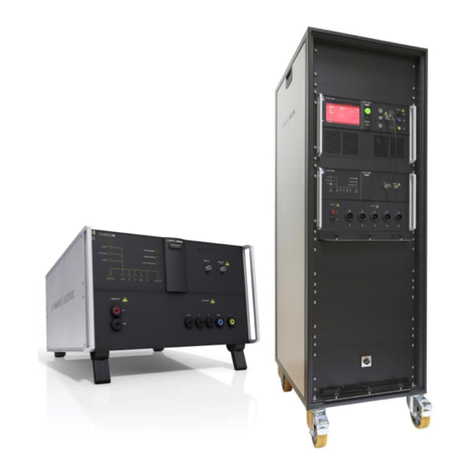
EMTEST EFT 500 Series Instruction Manual

Manual
for Operation
EFT 500
EFT/burst generator pulse 5/50ns
EFT500 – an EFT/Burst generator – is an intelligent solution
offering exactly what you need for full-compliance immunity
tests against Electrical/Fast transients phenomena. The distinct
operation features, convenient DUT connection facilities, a
clearly arranged menu structure and display philosophy as well
as the pre-programmed standard test routines make testing
easy, reliable and safe.
Extendable by a variety of test accessories the EFT 500 is a
universal equipment for abroad range of recommendations even
for three-phase applications up to 100A
•IEC 61000-4-4
•IEC 61000-4-4 Ed 2
•EN 61000-4-4
•EN 61000-4-4 Ed 2
Version: 2.00 / 15.07.2004
emc test equipment Replaces: 1.00 / 24.11.1997
Filename: eft500 operating manual v200.doc
Printdate: 15.07.04

EM TEST EFT 500 Series
Manual for Operation V 2.00 2 / 21
Contens
1. Operating Functions .....................................................................................................................................3
1.1. Front view.........................................................................................................................................3
1.2. Rear view .........................................................................................................................................4
2. Operation........................................................................................................................................................5
2.1. Description of the menus .................................................................................................................5
2.2. Main Menu .......................................................................................................................................5
2.3. Quick Start .......................................................................................................................................6
2.4. User Test Routines ..........................................................................................................................7
2.5. Test Routine as per IEC 61000-4-4 (2004-07) Ed 2 ........................................................................9
2.6. Service .............................................................................................................................................9
2.7. Setup..............................................................................................................................................10
3. Test Equipment EFT 500.............................................................................................................................11
3.1. Specification of the test parameters ..............................................................................................11
3.2. Burst generation.............................................................................................................................11
3.3. Coupling decoupling network.........................................................................................................12
3.3.1. Coupling/decoupling network for ac/dc power lines ......................................................................12
3.3.2. Capacitive coupling clamp .............................................................................................................12
3.4. Burst Test Setup ............................................................................................................................13
3.5. Computer setup for EFT/Burst testing. ..........................................................................................14
4. Technical data .............................................................................................................................................16
4.1. EFT Electrical Fast Transients Burst as per IEC 61000-4-4.............................................................16
5. Maintenance.................................................................................................................................................17
5.1. General ..........................................................................................................................................17
5.2. Test set-up .....................................................................................................................................17
5.3. Calibration and verification.............................................................................................................17
6. Delivery Groups...........................................................................................................................................18
6.1. Basic equipment ............................................................................................................................18
6.2. Accessories and options ................................................................................................................18
7. Appendix ......................................................................................................................................................19
7.1. Declaration of CE-Conformity ........................................................................................................19
7.2. EFT 500 - General Diagram...........................................................................................................20
7.3. EFT 500 - Overview .......................................................................................................................20
7.4. EFT 500 Menu overview ...............................................................................................................21

EM TEST EFT 500 Series
Manual for Operation V 2.00 3 / 21
1. Operating Functions
1.1. Front view
1Display
2"Test On"
3Function keys "F1..F7"
4Knob (Inc / Dec)
5Cursor keys "←" and "→"
6Exit
7Escape
8CRO
9HV pulse output 50 ohm
10 Ground reference
11 Coupling “On”
12 EUT test supply
1Display
All functions and parameters are displayed (8 lines with max. 40 characters).
2 Test On
By pressing the key "Test On" the test procedure is initiated with the preselected parameters. The red LED
indicates the trigger of a burst event.
3 Function keys "F1 .. F7"
Parameters and functions, displayed in the lowest line, can be selected with the related function key.
4 Knob (Inc / Dec)
The knob increments or decrements test parameters with a numeric value or selects from a list of parameters.
5 Cursor keys
Parameters and functions can be changed on-line. The selection of these parameters is realized with the cursor
moving to the left or to the right.
6Exit
Pressing of the Exit function will cause a reset of the firmware. This is only possible if no test routine is running.
7 ESC
When pressing the ESC button the user moves back one page in the menu.
8 BNC - CRO Trigger
At the BNC output the generator trigger can be checked, e.g. the burst duration, the burst repetition rate and the
spike frequency (+15 V rectangular). This output signal can also be used to trigger external measuring devices
(e.g. an oscilloscope)
9 HV pulse output 50 ohm
External coupling devices such as the capacitive coupling clamp and the coupling network CNE 503 are
connected to the coaxial 50 ohm output. Also the pulse parameters, on 50Ωand 1000Ωload condition, must be
verified at this coaxial output.
10 Ground reference
During test or calibration procedure the burst generator must be grounded to the reference ground plane.
11 Coupling
The LED indicates that the pulses are coupled to the L –N –PE line.
12 EUT test supply
The coupling / decoupling network is part of the generator. The EUT is powered via the safety laboratory plugs
at the front panel of the simulator. The nominal power mains supply is 250V/16A. For higher currents, up to
100A, the external coupling network CNE 503 shall be used.

EM TEST EFT 500 Series
Manual for Operation V 2.00 4 / 21
1.2. Rear view
EXT TRIGGER
SAFETY CIRCUIT
115
230
115
230
RS 232 CN
IEEE 488
1
2
3
478
9
6
FAIL 2
FAIL 1
10
1DUT test supply input
2Reference earth connection
3External trigger
4Mains selector 115V / 230V
5Power on switch
6Safety circuit
7Serial interface RS 232
8Remote control connector CN
9 Parallel interface GPIB / IEEE 488
10 Fail input Fail 1and Fail 2
1 DUT test supply input
The power supply for the EUT is connected to the safety laboratory connectors + and -. The front panel output is
decoupled by the internal coupling/ decoupling network.
2 Reference ground connection
The generator has to be connected to the reference ground plane of the test set up. Very important is the
connection at the front panel of the simulator.
3 External trigger
One single burst event can be released. Trigger level 5-15V positive going.
4 Mains selector
Selection of 115V / 230V
5 Power on switch
The switch is part of the mains filter. Mains fuses are part of the filter. (230V / 1A and 115V / 2A )
6 Safety circuit
To connect an external security circuit.
7 Serial interface
RS 232 interface with a 9-pole connector.
8 Remote control connector CN
To connect to the external coupling matrix CNE 503. All functions are controlled by the EFT 500. It is
recommended to connect and power the CNE 503 before turning the power mains ON at the EFT 500.
9 Parallel interface GPIB / IEEE 488
IEEE 488 interface with IEEE connector.
10 Fail detection FAIL 1 (TEST STOP)
The BNC input FAIL 1 can be used for DUT monitoring. In case of a low going signal (to chassis ground) the
EFT 500 will stop pulse generation and the actual running test routine is paused. The test routine than can be
stopped completely or can be continued from break point.
A message of FAIL 1 is indicated in the LCD display as well as in the ISM ISO software.
10 Fail detection FAIL 2 (TEST PAUSE)
The BNC input FAIL 2 can be used for DUT monitoring In case of a low going signal (to chassis ground) the
EFT 500 will stop pulse generation and the actual running test routine is paused as long as the low level signal
is available at the FAIL 2 input.
The test routine continues automatically as soon as the low level signal goes to high level.
A message of FAIL 2 is indicated in the LCD display as well as in the ISM ISO software.

EM TEST EFT 500 Series
Manual for Operation V 2.00 5 / 21
2. Operation
2.1. Description of the menus
The simulator is operated by an easy menu control system.
Seven function keys are available to select parameters and
functions.
The selected parameter is blinking and can be changed by turning the knob (incr./decr.).
The digit to be changed can be selected with the cursor (ÍÎ ).
ESC will take you back to the previous level in the menu and set the displayed values. The
latest settings are stored automatically and will be recalled when the menu is selected
again.
EXIT will reset the firmware to the main screen.
All functions are indicated on the display; max. 8 lines and 40 characters.
EM TEST
EFT 500
Burst 5/50ns
V 3.20 SWN: 001234
Start-up display example EFT 500
The serial number and the version number SWN are used for traceability reasons. These numbers are listed in
the test reports and calibration certificates. These numbers also are listed within the test reports generated by the
ISM ISO software
2.2. Main Menu
MAIN MENU
F1 : Quickstart
F2 : User test routines
F3 : Standard test routines acc IEC 61000-4-4
F7 : Service
F1 F2 F3 F4 F5 F6 F7
Quick Start
Easy and fast operation of the equipment without special functions. All parameters can be adjusted during the
running test.
User Test Routines
The user can program, save and recall his own specific test routines. He can select standard routines or special
functions such as automatic change of voltage or frequency during a test routine.
Test Routines as per IEC 61000-4-4
The user can call up the standard routines as per IEC 61000-4-4 and start them immediately.
Service
Set-up menu of the generator.

EM TEST EFT 500 Series
Manual for Operation V 2.00 6 / 21
2.3. Quick Start
Easy and very fast operation of all standard functions of the equipment. The latest simulator settings are stored
automatically and will be recalled when Quick Start is next selected.
QUICK START
V = 2000V f = 5.0kHz
td = 15.0ms tr = 300ms
kop = L N PE +/- = +
T = 5:00min
START CHANGE PRINT
F1 F2 F3 F4 F5 F6 F7
Press CHANGE and the test parameters parameter can be changed.
Select the desired parameter with the related function key and change the value by turning the front panel knob.
The cursor allows the user to define the digit to be changed (fast or slow change).
Press START and the test starts immediately with the displayed test parameters.
The operator now can navigate with the Cursor from parameter to parameter. The blinking parameter can be
changed by turning the front panel knob.
Press ESC will bring the user back to the previous menu level.
Page 3 (Change)
QUICKSTART
Voltage V : 200V - 4400V
Frequency f : 0.1kHz - 1000.0kHz
Duration td : 0.1ms - 999.9ms
Repetition tr : 10ms - 9999ms
Test time T : 0:01min - 99:59min
U f td tr kop +/- T
200 5.0 15.0 300 L N PE + 5:00
F1 F2 F3 F4 F5 F6 F7
After starting the test the elapsed testtime is displayed. All
function keys except F2 (manual trigger) can Stop the test
routine. After test stop ( Stop, Test OFF), the display keeps for
about 2s.
Burst Spezifikation gemäss IEC 61000-4-4 (2004-07) Ed 2
f = 5kHz 100kHz
tr = 15ms 0.75ms
td = 300ms 300ms

EM TEST EFT 500 Series
Manual for Operation V 2.00 7 / 21
2.4. User Test Routines
The user can program, save and recall his own specific test routines. The next pages shows the selection of the
functions.
USER TEST ROUTINES Page 1 / 2 USER TEST ROUTINES Page 2 / 2
F1 : Customized test routines F1 : Change duration after T by ∆dt
F2 : Voltage change after T by ∆VF2 : Change polarity after T
F3 : Frequency change after T by ∆f F3 : Random burst release
F4 : Frequency sweep in one single burst F4 : Synchronized at fixed angle
Page 2 Page 1
F1 F2 F3 F4 F5 F6 F7 F1 F2 F3 F4 F5 F6 F7
Each of these special functions can include 7 stored test routines.
CUSTOMISED TEST ROUTINES
F1 : Store F1 F5 : Store F5
F2 : Store F2 F6 : Store F6
F3 : Store F3 F7 : Store F7
F4 : Store F4
F1 F2 F3 F4 F5 F6 F7
After selection of a stored test file the test parameters will be indicated on the display.
Customized test routines
The software controls standard test routines according to the specification of the user. All limitations are the same
as defined under Quick Start.
Voltage change after T by ∆V
The test voltage is increased from V1 to V2 by steps of ∆V
after the defined test time T. All limitations are the same as
defined under Quick Start. The limitation of the max.
generated number of spikes is related to the higher voltage
of V1 or V2.
Frequency change after T by ∆f
The spike frequency is increased from f1 to f2, and then
from f2 to f3 by steps of ∆f after the defined test time T. All
limitations are the same as defined under Quick Start. The
limitation of the max. generated number of spikes is related
to the higher frequency of f1 , f2 or f3.

EM TEST EFT 500 Series
Manual for Operation V 2.00 8 / 21
tr >= 100ms
f1 <= f2
td >= 5.0ms
td >= 5 / f1
Frequency sweep in one single burst
During one single burst the frequency sweeps from f1 to f2.
For this function the following limitations have to be
respected:
tr -td >= 50ms
Duration change after T by ∆t4
The burst duration is increased from t4s to t4e by steps of ∆
t4 after the defined test time T. All limitations are the same
as defined under Quick Start. The limitation of the max.
generated number of spikes is related to the higher duration
of t4s or t4e.
Random burst release
No repetition rate is selected. The single burst will be
triggered randomly within the limits of 20 to 2000ms as time
between two bursts. All limitations are the same as defined
under Quick Start.
Change coupling after T
The coupling mode will be changed after the defined test
time T. All modes will be tested.
Polarity change after T
The polarity will be changed from + to - after the defined test
time T.

EM TEST EFT 500 Series
Manual for Operation V 2.00 9 / 21
2.5. Test Routine as per IEC 61000-4-4 (2004-07) Ed 2
The display shows a list of test levels as per the standards IEC 61000-4-4. In the menu Service F4Change
standard level you select between the burst frequency 5kHz and 100kHz.
Setting IEC 61000-4-4 Setting IEC 61000-4-4 Ed 2
STANDARD TEST ROUTINES STANDARD TEST ROUTINES
F1 : Level 1 260 V / 5.0 kHz F1 : Level 1 260 V / 100.0 kHz
F2 : Level 2 500 V / 5.0 kHz F2 : Level 2 500 V / 100.0 kHz
F3 : Level 3 1000 V / 5.0 kHz F3 : Level 3 1000 V / 100.0 kHz
F4 : Level 4 2000 V / 5.0 kHz F4 : Level 4 2000 V / 100.0 kHz
F5 : Level 5 4000 V / 5.0 kHz F5 : Level 5 4000 V / 100.0 kHz
F6 : Level X - Level Y F6 : Level X - Level Y
F1 F2 F3 F4 F5 F6 F7 F1 F2 F3 F4 F5 F6 F7
The function key F5 selects a procedure which starts at test level X and stops at test level Y. The test level is
changed automatically after the preselected test time T.
(X <= Y)
Page 3 (Show values)
Standard IEC 1000-4-4 Level 3
V = 2000V f : 100 kHz
td = 0.8ms tr : 300ms
kop = L N PE +/- : +
T = 1:00min
The Standard defines the burst duration at
100kHz with 0.75ms. The EFT 500 does not
support a resolution of 0.05ms.
The burst duration at 100kHz is set to 0.8ms
which is inside the specified tolerance of the
standard of 0.75ms ±20%
F1 F2 F3 F4 F5 F6
The functions START, CHANGE and PRINT are the same as defined under Quick Start.
The function key CHANGE can only handle the coupling, polarity and the test time.
All other parameters are defined by the standard.
2.6. Service
SERVICE
F1 : Address EM TEST AG
F2 : Selftest
F3 : Set-up
F4 : Change standard levels
F5 : Print all
F1 F2 F3 F4 F5 F6 F7
F1 Addresses
All important data regarding EM TEST are indicated.
F2 Selftest
Selftest for check the key functions.
F3 Set-up
The software will clearly explain the set-up procedure.
F4 Change standard levels
This procedure allows the user to change the standard values to his actual requirements.
F5 Print all
All stored settings are printed to the serial interface RS 232.

EM TEST EFT 500 Series
Manual for Operation V 2.00 10 / 21
2.7. Setup
SETUP
F1 : Change language
F2 : LCD backlighting
F3 : Interfaces
F4 : Keyboard-Beeper
F5 : Timer
F6 : Safety circuit
F1 F2 F3 F4 F5 F6 F7
Change language
The user can chose between two languages, German and English.
LCD backlighting
With the use of F2 the backlighting can be switched On or Off. Additionally the Auto Off function can be
programmed to switch off the backlighting after a specified time the generator has not been in operation (1 -
30min).
Interfaces
This menu will help the user to define the status of the integrated serial and parallel interfaces, e.g. the baud rate
of the RS 232 or the address of the IEEE interface.
Keyboard-Beeper
F1 is the selector for the beeper ON/OFF mode.
The beeper is always on when a test routine is finished. To indicate that a running test is finished the beeper
sounds 3 times.
Timer
Pressing of F5 will show the total operating time of the test equipment.
Safety circuit
F6 shows the state of the security circuit. It can be switched on and off.

EM TEST EFT 500 Series
Manual for Operation V 2.00 11 / 21
3. Test Equipment EFT 500
3.1. Specification of the test parameters
As per IEC 61000-4-4 the EFT pulses are specified as follows:
V
t
td
tr
10%
50%
90%
100%
VS
Definition of a single pulses
V
t
t4
VS
0
f1
t5
Definition of a complete burst
Parameter on a 50 Ωload on a 1000 Ωload
VS 125V – 2000V 250V - 4000V
Ri 50Ω50Ω
td 50ns ±30% 35ns – 150ns
tr 5ns ±30% 5ns ±30%
f1 5kHz/2.5kHz 5kHz/2.5kHz
t4 15ms 15ms
t5 300ms 300ms
3.2. Burst generation
Discharge switch:
The discharge switch is a highly reproducible semiconductor switch. Spike frequencies up to 1000kHz are by a
factor of 200 higher than recommended in the actual EFT standards. This means of course that also the pulse
energy would be 200 times higher. This is not generally possible for the high voltage switch. Therefore the
following limitation protects the pulse forming circuit against overload:
Voltage U max. pulse / burst
td * f
max. pulse / s
td * f / tr
< 1'500V 1,000 10,000
>= 1'500V < 2'500V 1,000 linear decrease to 5,000
>= 2'500V linear decrease to 500 linear decrease to 1,500

EM TEST EFT 500 Series
Manual for Operation V 2.00 12 / 21
3.3. Coupling decoupling network
The decoupling part of the coupling network has to:
- filter the interference pulses in the direction to the power supply;
- protect other systems that are connected to the same power supply and
- realize a high impedance of the power supply, e.g. battery supply.
3.3.1. Coupling/decoupling network for ac/dc power lines
The coupling network has to couple the interference pulses to the lines of a power supply system (AC or DC). As
coupling devices capacitors of sufficient strength and bandwidth shall be used according to IEC 61000-4-4.
Coupling network acc. to IEC 61000-4-4
L1 L2
L
N
Cx
Cy
PE
Cy
L1 L2
LE
L
N
PE
EFT 500
Ck
The coupling on signal lines can usually not be effected capacitively without interfering with the signal flow. It is
often impossible to contact the required circuit (direct), e. g. coaxial or shielded cables. In this case the coupling
is realized with the capacitive coupling clamp. The interference simulator can be connected on both sides of the
coupling clamp.
3.3.2. Capacitive coupling clamp
- The coupling clamp is not matched by 50 ohm. If the clamp is matched there exists an additional magnetic
coupling, which may cause completely different test results.
- The clamp should be placed in a distance of 0.5m to the equipment under test. When using shorter distances,
the EUT may be influenced by radiation.
- If the EUT is built up by two different equipment, the test should be conducted on each single equipment with
the required distance.
Generator
EFT 500
EUT 1 EUT 2
Signal Signal
Ground reference Capacitive coupling clamp
100 pF
Decoupling
network
Coupling to signal lines or lines where no galvanic
contact is possible (e.g. shielded lines)
0.1m
Decoupling network
Net
Net
0.5m
0.5m

EM TEST EFT 500 Series
Manual for Operation V 2.00 13 / 21
3.4. Burst Test Setup
- The test generator and the coupling network should be connected to the reference ground plane (acc. to high
frequency requirements).
- The equipment under test must be isolated from the reference ground plane. The distance should be 10cm.
Being part of the EUT, these requirements are also recommended for all connected cables. The EUT should
only be grounded if this is recommended by the installation guideline. For safety reasons, the test without any
ground connection should be conducted as well (at 100MHz 1m ground cable has an impedance of about 600
ohm)
- Whenever possible the test set-up and the cabling should always be the same; e.g. for testing power lines it
would be possible to fix the cables on the test table for all tests in the same way.
- Lines under test and all other lines should be decoupled strictly.
Generator
EFT 500
EUT
Ground reference
Coupling to power supply lines
>Net
<= 1 m
Coupling Network
Ck
Z
L1 L2 L3
N
PE
10cm

EM TEST EFT 500 Series
Manual for Operation V 2.00 14 / 21
3.5. Computer setup for EFT/Burst testing.
During immunity tests high frequency interference is generated. Due to the length of the connected lines, a
certain part of this energy will be transformed into radiated interference.
Therefore the operator shall be aware that systems and installations in the neighborhood, even those not being
part of the test set-up can be disturbed.
Especially for fully automated test systems, where simple computers may be used, EMC problems within the test
system may occur. To avoid such disturbances in the following paragraphs some information is given to which
the operator has to taken care:
- EM TEST generators are tested with the maximum test level. If no damage has been occurred the equipment
must be seen as immune.
- The interference always will enter into a system at the weakest part. Within a computer controlled system the
weakest unit is almost the computer with its interconnection lines and the peripheral equipment.
- The most critical test concerning the above mentioned problems is the burst test according to IEC 1000-4-4.
This is a high frequency test, which may radiate extreme interference fields to the environment.
Concerning the test set-up the following points be explained:
1. The burst generator must be connected very good to the ground reference plane on the table.
2. The ground reference plane shall be connected to the protective earth system. For tests within a shielded
room the connection shall be made to the walls of the room.
3. The test set-up shall have one single ground reference point (not several)
GROUND LOOPS SHALL BE STRICTLY AVOIDED
4. The central ground reference point shall be located where the EFT generator is connected to the ground
reference plane. At the same point the reference ground plane shall be connected to the protective earth
system or to the shielded room.

EM TEST EFT 500 Series
Manual for Operation V 2.00 15 / 21
For conducting the test the following points shall be taken under consideration:
1. It is not allowed to touch the EUT or the cables under test during a running test. The test results will be
influenced and are no more reproducible.
2. If the operator in contrary touches directly the EUT or the connected lines increased radiation from the test
set-up is generated. The operator itself will radiate and/or will cause ground currents into the whole
environment.
3. As larger the dimensions of an EUT are, as higher the radiation of high frequency energy will be.
4. Especially the capacitive coupling clamp with its length of 1m radiates.
5. Auxiliary equipment as well as computer can be influenced directly due to the radiation.
Remarks:
Even the use of fiber-optic links for the communication between a computer and EFT does not help in case of
direct radiation. The computer and its lines will be directly influenced and the data transmission will be disturbed.
6. The influence of direct radiation can be reduced by increasing the distance between a computer and the test
set-up. In any case a minimum distance of 3m shall be available.
It is not only the length of the cable but also the physical distance between computer and test set-up which is
important to take care to.
7. It is shall be strictly avoided to put the computer directly onto the ground reference plane of the test set-up.
The computer then is part of the test set-up and will also be tested. Mostly all computers are not immune to
this test and will be disturbed.
What to say about the computer:
1. Do not use oldest equipment available in your company. Actual computer show better behavior to what EMC
concerns.
2. Do not use notebooks for this application. Laptops are fully manufactured within a plastic housing and therefore
are very sensitive to all kind of interference.
4. It would be better to use tower- or mini-tower equipment. They are at least partially screened. The interface
connectors are mounted on metallic surfaces so that the screen of the communication lines can be connected
to the chassis.
5. The screens of the RS 232 and IEEE cables must be connected to the chassis of the instruments at both
sides, at the computer and at the EFT generator.
6. The communication cables, RS 232 and IEEE, shall be screened. Do not use standard cables, consumer products
with plastic connectors.
These cable types are using mostly very bad designed cable screens. The contact to the housing of the
connector is mostly realized with a small cable, which is very bad under the aspect of rf screening.
Please take care that the screen is connected very good to the metallic housing of the connector and that the
connector is screwed to the housing of the generator.
This mostly is the problem when using the RS 232 interface. Especially those cables are badly designed. For IEEE
cables very good products are available (e.g. HP).
7. The weakest parts within the computer system are the peripherals, as keyboard and mouse. Both products
are not designed to operate under these severe conditions.
It is very easy to make the design better. The operator would be able to do it for himself.
What is the problem ?
The screen of the cables between a computer and the keyboard (mouse) are soldered directly to the printed
circuit board.
The screen shall not be soldered to the print, but to another „ground reference plane“.
e.g. put into the keyboard, directly under the keyboard print a broad copper foil area. Connect the screen of the
cable to this copper foil, without any connection to the print. You will see a dramatic change to better results.

EM TEST EFT 500 Series
Manual for Operation V 2.00 16 / 21
4. Technical data
4.1. EFT Electrical Fast Transients Burst as per IEC 61000-4-4
Test Level
Open circuit 200V - 4400V ± 10% Step 10V
Wave shape into a 50Ωload 100V – 2200V
Rise time tr 5ns ± 30%
Pulse duration td 50ns ±30%
Wave shape into a 1000Ωload 200V – 4400V
Rise time tr 5ns ± 30%
Pulse duration td 35ns - 150ns
Source impedance Zq = 50Ω± 20%
Polarity positive / negative
Trigger
Trigger of bursts AUTO, MANUAL, EXTERN
Synchronization 0° - 360°
Burst duration td 0.1ms - 999.9ms
Burst repetition rate tr 10ms - 9999ms
Spike frequency f 0.1kHz - 1000kHz
Test duration T 0:01 min - 99:59 min
Output
Direct via 50Ωcoaxial connector To connect ext. coupling devices
Coupling network To L, N, PE all combinations
DUT power mains supply AC 250 V / 16 A / 50/60 Hz
DC 250V/10A
Test routines
Quick Start Immediate start, all parameters adjustable during a running test
Standard test as per IEC 61000-4-4 level 1 ... level 5
Level X - Level Y
User test routines Customized test routines
Voltage change after T by ∆V
Frequency change after T by ∆f
Frequency sweep in one single burst
Change duration after T by ∆td
Change polarity after T
Statistical burst release
Synchronized at fixed angle
Safety
Safety circuit Control input ( short circuit )
Design as per IEC 1010, EN 61010
Interfaces
RS 232 serial, 1200 - 19200 Baud
IEEE parallel, addresses 1-30
CN port Control of CNE 503 for 3-ph testing
General data
Dimensions 19" / 3 HUE
Weight approx. 8kg
Power supply 115V/230V +10/-15% 50/60Hz
Fuses 2 x T 1A slow blow

EM TEST EFT 500 Series
Manual for Operation V 2.00 17 / 21
5. Maintenance
5.1. General
The generator is absolutely maintenance-free by using a solid state semiconductor switch to generate transients.
5.2. Test set-up
When setting up the test national and international regulations
regarding human safety have to be guaranteed.
It is recommended to connect the simulator to the ground reference
plane of the test set-up.
The generators of the series 500, UCS, VCS, CSS, TSS and CNI, can
be linked together to a fully automotive test set-up.
The set-up communicates via the IEEE / GPIB bus and is controlled by
ISMIEC software. For setting up the system see the following figures:
Each generator can be operated individual as a single equipment.
5.3. Calibration and verification
The EM Test equipment are calibrated in the factory and marked with a
calibration-tag. The measuring instrument is traceable to the Swiss Federal
Office of Metrology.
The calibration date is marked. The validity of the calibration is in the area of
responsibility of the users quality system.
Example: EM Test calibration-tag
Please refer to the corresponding standard before proceed a calibration or verification. The standard describes
the procedure, the tolerances and the necessary auxiliary means. There are suitable calibrations adapters to use.
All calibrations and verifications are always without mains supply voltage on the impulse- or coupling network
output.
Danger
Before starting the calibration or verification
remove the EUT Mains Supply
from the generator and from the coupling network

EM TEST EFT 500 Series
Manual for Operation V 2.00 18 / 21
6. Delivery Groups
6.1. Basic equipment
•EFT/burst generator type EFT 500
•Mains cable
•Mains cable for the EUT supply
•Adapter for power cable
•Manual
•Calibration certificate
6.2. Accessories and options
•50 Ωmatching resistor (1:100) type KW 50
•1000Ωmatching resistor (1:1000) type KW 1000
•Capacitive coupling clamp HFK as per IEC 61000-4-4
-External coupling/decoupling network 3 - phase CNE 503
-EUT mains supply 400 V rms max. // 480V for USA
-Nominal current In = 16 A / 32A / 63A / 100 A rms
-Frequency 50/60 Hz
-Coupling to all lines . Lx, N, PE
-50ΩBurst output
-The coupling will be controlled by the EFT 500
•ITP immunity test probe set
•User software "ISM IEC"
Test, analysis and documentation with windows (see separate documentation)

EM TEST EFT 500 Series
Manual for Operation V 2.00 19 / 21
7. Appendix
7.1. Declaration of CE-Conformity
Manufacturer : EM TEST AG
Address: Sternenhofstr. 15
CH 4153 Reinach
Switzerland
declares, that under is sole responsibility, the product’s listed below, including all their options, are conformity with the
applicable CE directives listed below using the relevant section of the following EC standards and other normative
documents.
Product‘s name: Burstgenerator EFT 500
Model Number(s) EFT 500
Low Voltage Directive 73/23/EEC
Standard to which conformity is declared:
EN 61010-1:1993 Safety
EMC Directive 89/336/EEC
Standard(s) to which conformity is declared:
Emissions:
EN 50081-2 : 1992
EN 50022:1987, Class A
EN 61000-2-3 A14: 2000
Conducted and radiated.
Harmonics
Immunity: EN 50082-2: 1995 EN 61000-4-2:1995 Electrostatic Discharges
EN 50413:1993 RF Electromagnetic Field
EN 61000-4-6:1997 Conducted RF
EN 61000-4-4: 1995 Electrical Fast Transient / Burst
EN 61000-4-5: 1996 Surge
EN 61000-4-11: 1994 DIPS & Voltage Variations
European representative Manufacturer
EM TEST GmbH EM TEST AG
Lünenerstr. 211 Sternenhofstr. 15
D 59174 Kamen CH 4153 Reinach
Tel: 00492307-18042 Tel: 004161-7179191
Fax: 00492307-17050 Fax: 004161-7179199
By U. Flor
General manager
H. Kunkel
Design and Research
Place Kamen, Germany Reinach BL , Switzerland
Date 11. November 2002 11. November 2002

EM TEST EFT 500 Series
Manual for Operation V 2.00 20 / 21
7.2. EFT 500 - General Diagram
7.3. EFT 500 - Overview
Table of contents
Other EMTEST Inverter manuals
Popular Inverter manuals by other brands
MULTIQUIP
MULTIQUIP GA-6HA Starting instructions
Sunways
Sunways NT 10000 user manual
Agilent Technologies
Agilent Technologies 16522A user guide
SOLIS
SOLIS Solis-EPM3-5G-Plus Quick installation instructions

Outback Power Systems
Outback Power Systems FX Series installation manual
FRONIUS
FRONIUS Symo GEN24 6.0 operating instructions
