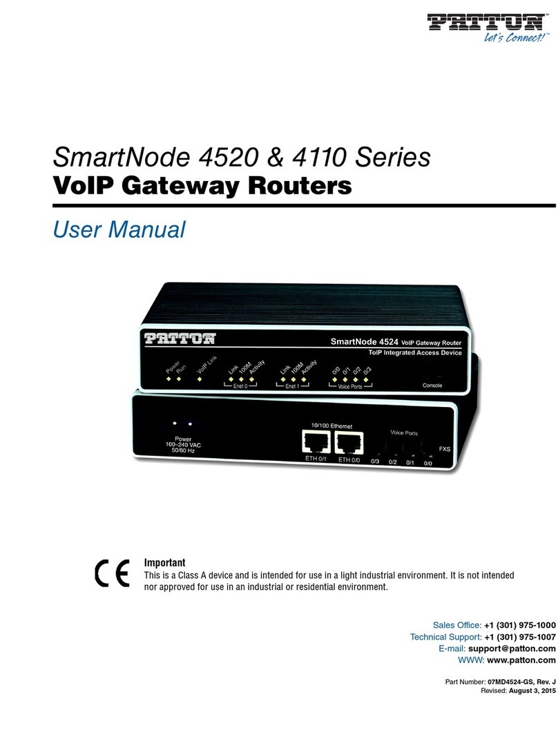
ADMtek ADM5120 User manual

ADM5120
HOME GATEWAY CONTROLLER
Datasheet
Version 1.13
ADMtek.com.tw
Information in this document is provided in connection with ADMtek products. ADMtek may make
changes to specifications and product descriptions at any time, without notice. Designers must not rely on
the absence or characteristics of any features or instructions marked “reserved” or “undefined”. ADMtek
reserves these for future definition and shall have no responsibility whatsoever for conflicts or
incompatibilities arising from future changes to them
The products may contain design defects or errors known as errata, which may cause the product to deviate
from published specifications. Current characterized errata are available on request. To obtain the latest
documentation please contact you local ADMtek sales office or visit ADMtek’s website at
http://www.admtek.com.tw
Copyright 2003 by ADMtek Incorporated All Rights Reserved.
*Third-party brands and names are the property of their respective owners.

ADMtek Inc. V1.13
About this Manual
Structure
This Data sheet contains 6 chapters
Chapter 1 Product Overview
Chapter 2 Interface Description
Chapter 3 Function Description
Chapter 4. Register Description
Chapter 5 Electrical Packaging
Chapter 6. Packaging
Customer Support
ADMtek Incorporated,
2F, No.2, Li-Hsin Rd.,
Science-based Industrial Park,
Hsinchu, 300, Taiwan, R.O.C.
Sales Information
Tel + 886-3-5788879
Fax + 886-3-5788871
ADM5120

ADMtek Inc. V1.13
Revision History
ADM5120
Date Version Change
19 March 2003 1.0 First release of ADM5120
05 June 2003 1.1 3.4, 4.5, 4.6, 4.7, 4.8 and 5.3 sections added. Updated pin
numbers.
13 June 2003 1.11 Updated Table for Clock Speeds
08 October 2003 1.12 2.2.5 Memory Bus : A[2]
2.2.10 PCI added CLK I/P
2.2.11 USB added CLK I/P
2.2.14 Corrected pin name
2.2.15 Changed I to O
4.4.1 Switched bits
4.4.11 Removed bits 31 – 17
4.4.12 Bits 31 – 30 bit error
4.4.13 Added bit [6]
29 October 1.13 2.2.5 Added default value to A[0], A[1] & A[13]
2.2.9 Added note

ADMtek Inc. V1.13
Table of Contents
CHAPTER 1 PRODUCT OVERVIEW ......................................................................1-1
1.1 OVERVIEW ............................................................................................................ 1-1
1.1.1 Product Order Information......................................................................1-1
1.2 FEATURES ............................................................................................................. 1-2
1.3 BLOCK DIAGRAM.................................................................................................. 1-3
1.4 ABBREVIATIONS ................................................................................................... 1-3
1.5 CONVENTIONS ...................................................................................................... 1-5
1.5.1 Data Lengths............................................................................................1-5
1.5.2 Register Descriptions...............................................................................1-5
1.5.3 Pin Descriptions.......................................................................................1-5
CHAPTER 2 INTERFACE DESCRIPTION..............................................................2-1
2.1 PIN ASSIGNMENT .................................................................................................. 2-1
2.1.1 324BGA Ball assignment.........................................................................2-1
2.1.2 208PQFP pin assignment........................................................................2-3
2.2 PIN DESCRIPTION BY FUNCTION............................................................................ 2-4
2.2.1 Network Media Connection .....................................................................2-5
2.2.2 Clock for Network....................................................................................2-5
2.2.3 LED..........................................................................................................2-5
2.2.4 GMII/MII Management............................................................................2-6
2.2.5 Memory Bus.............................................................................................2-7
2.2.6 SDRAM Control Signals..........................................................................2-8
2.2.7 UART........................................................................................................2-8
2.2.8 JTAG........................................................................................................2-9
2.2.9 General Purpose I/O (GPIO)...................................................................2-9
2.2.10 PCI...........................................................................................................2-9
2.2.11 USB........................................................................................................2-10
2.2.12 NAND Flash...........................................................................................2-10
2.2.13 External CS/INT/wait.............................................................................2-10
2.2.14 Power and Ground.................................................................................2-12
2.2.15 Regulator Interface................................................................................2-12
2.2.16 Miscellaneous ........................................................................................2-12
CHAPTER 3 FUNCTION DESCRIPTION................................................................3-1
3.1 SYSTEM................................................................................................................. 3-1
3.1.1 Frequency ................................................................................................3-1
3.1.2 Boot code data-width...............................................................................3-1
3.1.3 GMII/MII port..........................................................................................3-1
3.2 PHY...................................................................................................................... 3-2
3.2.1 PHY Overview..........................................................................................3-2
3.2.2 Link Detect...............................................................................................3-2
3.2.3 Auto-Negotiation......................................................................................3-2
3.2.4 Digital Adaptive Equalizer ......................................................................3-2
ADM5120 i
3.2.5 Clock Recovery ........................................................................................3-3

ADMtek Inc. V1.13
3.2.6 Stream Cipher Scrambler/ De-scrambler................................................3-3
3.2.7 Encoder/Decoder.....................................................................................3-3
3.3 SWITCH ENGINE.................................................................................................... 3-4
3.3.1 Hashing Function.....................................................................................3-4
3.3.2 Learning Process.....................................................................................3-4
3.3.3 Routing.....................................................................................................3-4
3.3.4 Forwarding..............................................................................................3-4
3.3.5 Buffer Management..................................................................................3-5
3.3.6 Flow Control (Patent Pending) ...............................................................3-5
3.3.7 Full Duplex ..............................................................................................3-5
3.3.8 Half Duplex..............................................................................................3-5
3.3.9 Packet priority and Class of Service (CoS) .............................................3-5
3.3.10 VLAN........................................................................................................3-6
3.3.11 Address table access................................................................................3-6
3.3.12 Address security.......................................................................................3-6
3.3.13 Bandwidth control function......................................................................3-7
3.3.14 Send descriptors content..........................................................................3-7
3.3.15 Receive descriptors content .....................................................................3-8
3.4 USB 1.1 HOST CONTROLLER.............................................................................. 3-10
3.4.1 Block Diagram.......................................................................................3-10
3.4.2 System bus interface...............................................................................3-10
3.4.3 Operational Register..............................................................................3-10
3.4.4 SIE..........................................................................................................3-11
3.4.5 DPLL......................................................................................................3-11
3.4.6 Memory BIST.........................................................................................3-11
3.5 DMA OPERATION............................................................................................... 3-11
3.5.1 Endpoint Descriptor Format..................................................................3-11
3.5.2 Transfer Descriptor Format ..................................................................3-12
3.5.3 DMA operation ......................................................................................3-14
CHAPTER 4 REGISTER DESCRIPTION ................................................................4-1
4.1 SYSTEM MEMORY MAP ........................................................................................ 4-1
4.2 SYSTEM AND INTERRUPT REGISTERS .................................................................... 4-1
4.2.1 Interrupt Control Register Map...............................................................4-1
4.2.2. Interrupt Request Source Description .....................................................4-1
4.2.3 IRQ_status, offset: 0x00...........................................................................4-1
4.2.4 IRQ_raw_status, offset: 0x40...................................................................4-2
4.2.5 IRQ_enable, offset: 0x80 .........................................................................4-2
4.2.6 IRQ_enable_clear, offset: 0xc0 ...............................................................4-2
4.2.7 Reserved, offset: 0x10..............................................................................4-2
4.2.8 INT_Mode, offset: 0x14 ...........................................................................4-2
4.2.9 FIQ_status, offset: 0x18...........................................................................4-3
4.2.10 IRQ_test_source, offset: 0x1c..................................................................4-3
4.2.11 IRQ_source_sel, offset: 0x20...................................................................4-3
4.2.12 INT_level, offset: 0x24.............................................................................4-3
4.3 SWITCH CONTROL REGISTER MAP........................................................................ 4-4
ADM5120 ii
4.4 SWITCH CONTROL REGISTER DESCRIPTION .......................................................... 4-5

ADMtek Inc. V1.13
4.4.1 Code, offset: 0x00 ....................................................................................4-5
4.4.2 SftReset, offset: 0x04................................................................................4-6
Note: Whenever you write the register offset 0x04, the SftReset will be active.......4-6
4.4.3 Boot_done, offset: 0x08 ...........................................................................4-6
4.4.3 SWReset, offset: 0x0c...............................................................................4-6
4.4.5 Global_St, offset: 0x10.............................................................................4-6
4.4.6 PHY_St, offset: 0x14................................................................................4-7
4.4.7 Port_St, offset: 0x18.................................................................................4-7
4.4.8 Mem_control, offset: 0x1c .......................................................................4-8
4.4.9 SW_conf, offset: 0x20...............................................................................4-8
4.4.10 CPUp_conf, offset 0x24.........................................................................4-10
4.4.11 Port_conf0, offset 0x28..........................................................................4-10
4.4.12 Port_conf1, offset 0x2c ..........................................................................4-11
4.4.13 Port_conf2, offset 0x30..........................................................................4-11
4.4.14 Reserved, offset: 0x34............................................................................4-12
4.4.15 Reserved, offset: 0x38............................................................................4-12
4.4.16 Reserved, offset: 0x3c ............................................................................4-13
4.4.17 VLAN_GI, offset 0x40............................................................................4-13
4.4.18 VLAN_GII, offset 0x44...........................................................................4-13
4.4.19 Send_trig, offset 0x48.............................................................................4-13
4.4.20 Srch_cmd, offset 0x4c ............................................................................4-13
4.4.21 ADDR_st0, offset 0x50...........................................................................4-14
4.4.22 ADDR_st1, offset 0x54...........................................................................4-14
4.4.23 MAC_wt0, offset 0x58............................................................................4-14
4.4.24 MAC_wt1, offset 0x5c............................................................................4-14
4.4.25 BW_cntl0, offset 0x60 ............................................................................4-15
4.4.26 BW_cntl1, offset 0x64 ............................................................................4-15
4.4.27 PHY_cntl0, offset 0x68...........................................................................4-15
4.4.28 PHY_cntl1, offset 0x6c...........................................................................4-16
4.4.29 FC_th, offset 0x70..................................................................................4-16
4.4.30 adj_port_th, offset 0x74.........................................................................4-16
4.4.31 Port_th, offset 0x78................................................................................4-16
4.4.32 PHY_cntl2, offset 0x7c...........................................................................4-16
4.4.33 PHY_cntl3, offset 0x80...........................................................................4-17
4.4.34 Pri_cntl, offset 0x84...............................................................................4-17
4.4.35 VLAN_pri, offset 0x88............................................................................4-17
4.4.36 TOS_en, offset 0x8c ...............................................................................4-18
4.4.37 TOS_map0, offset 0x90..........................................................................4-18
4.4.38 TOS_map1, offset 0x94..........................................................................4-18
4.4.39 Custom_pri1, offset 0x98.......................................................................4-18
4.4.40 Custom_pri2, offset 0x9c .......................................................................4-18
4.4.41 PHY_cntl4, offset 0xA0..........................................................................4-19
4.4.42 Empty_cnt, offset 0xA4...........................................................................4-19
4.4.43 Port_cnt_sel, offset 0xA8.......................................................................4-19
4.4.44 Port_cnt, offset 0xAc..............................................................................4-19
ADM5120 iii
4.4.45 Int_st, offset 0xB0...................................................................................4-20

ADMtek Inc. V1.13
4.4.46 Int_mask, offset 0xB4.............................................................................4-21
4.4.47 GPIO_conf0, offset 0xB8.......................................................................4-22
4.4.48 GPIO_conf2, offset 0xBc .......................................................................4-22
4.4.49 Watchdog0, offset 0xC0.........................................................................4-22
4.4.50 Watchdog1, offset 0xC4.........................................................................4-22
4.4.51 Swap_in, offset 0xC8..............................................................................4-23
4.4.52 Swap_out, offset 0xCc............................................................................4-23
4.4.53 send_Hbaddr, offset 0xD0 .....................................................................4-23
4.4.54 send_Lbaddr, offset 0xD4......................................................................4-23
4.4.55 receive_Hbaddr, offset 0xD8.................................................................4-23
4.4.56 receive_Lbaddr, offset 0xDc..................................................................4-24
4.4.57 send_Hwaddr, offset 0xE0.....................................................................4-24
4.4.58 send_Lwaddr, offset 0xE4......................................................................4-24
4.4.59 receive_Hwaddr, offset 0xE8.................................................................4-24
4.4.60 receive_Lwaddr, offset 0xEc..................................................................4-24
4.4.61 Timer_int, offset 0xF0............................................................................4-24
4.4.62 Timer, offset 0xF4..................................................................................4-25
4.4.63 Reserved, offset 0xF8.............................................................................4-25
4.4.64 Reserved, offset 0xFc.............................................................................4-25
4.4.65 port0_LED, offset 0x100........................................................................4-25
4.4.66 port1_LED, offset 0x104........................................................................4-25
4.4.67 port2_LED, offset 0x108........................................................................4-25
4.4.68 port3_LED, offset 0x10c........................................................................4-26
4.4.69 port4_LED, offset 0x110........................................................................4-26
4.5 USB CONTROL STATUS REGISTER MAP ............................................................. 4-26
4.6 USB CONTROL STATUS REGISTERS DESCRIPTION.............................................. 4-27
4.6.1 General Control , offset 0x00.................................................................4-27
4.6.2 Interrupt Status, offset 0x04...................................................................4-27
4.6.3 Interrupt Enable, offset 0x08 .................................................................4-28
4.6.4 Reserved, offset 0x0C.............................................................................4-28
4.6.5 Host General Control, offset 0x10.........................................................4-29
4.6.6 Reserved, offset 0x14 .............................................................................4-29
4.6.7 SOF Frame interval, offset 0x18............................................................4-29
4.6.8 SOF Frame number, offset 0x1C...........................................................4-30
4.6.9 Reserved, offset 0x20 – 0x6C.................................................................4-30
4.6.10 Low speed threshold, offset 0x70...........................................................4-30
4.6.11 RH descriptor, offset 0x74 .....................................................................4-31
4.6.12 Port x status, offset 0x78........................................................................4-33
4.6.13 Host Descriptor Head Starting Address, offset 0x80.............................4-36
4.7 MPMC REGISTERS ............................................................................................. 4-36
4.7.1 MPMC Registers Summary....................................................................4-36
4.7.2 MPMC Control register, offset 000h.....................................................4-38
4.7.3 MPMC Status register, offset 004h........................................................4-38
4.7.4 MPMC Config register, offset 008h.......................................................4-39
4.7.5 MPMC Dynamic Control register, offset 020h......................................4-39
ADM5120 iv
4.7.6 MPMC Dynamic Refresh register, offset 024h......................................4-40

ADMtek Inc. V1.13
4.7.7 MPMC Dynamic RP register, offset 030h .............................................4-40
4.7.8 MPMC Dynamic RAS register, offset 034h ...........................................4-41
4.7.9 MPMC Dynamic SREX register, offset 038h.........................................4-41
4.7.10 MPMC Dynamic APR register, offset 03Ch..........................................4-41
4.7.11 MPMC Dynamic DAL register, offset 040h...........................................4-41
4.7.12 MPMC Dynamic WR register, offset 044h ............................................4-41
4.7.13 MPMC Dynamic RC register, offset 048h.............................................4-42
4.7.14 MPMC Dynamic RFC register, offset 04Ch..........................................4-42
4.7.15 MPMC Dynamic XSR register, offset 050h ...........................................4-42
4.7.16 MPMC Dynamic RRD register, offset 054h ..........................................4-42
4.7.17 MPMC Dynamic MRD register, offset 058h..........................................4-42
4.7.18 MPMC Static Extended Wait register, offset 080h................................4-43
4.7.19 MPMC Dynamic Config [0,1,2,3] register............................................4-43
4.7.20 MPMC Dynamic Ras Cas[0,1,2,3] register...........................................4-46
4.7.21 MPMC Static Config[0,1,2,3] register..................................................4-46
4.7.22 MPMC Static Wait Wen [0,1,2,3] register ............................................4-47
4.7.23 MPMC Static Wait Oen[0,1,2,3] register..............................................4-47
4.7.24 MPMC Static Wait Rd [0,1,2,3] register...............................................4-48
4.7.25 MPMC Static Wait Page [0,1,2,3] register ...........................................4-48
4.7.26 MPMC Static Wait Wr [0,1,2,3] register...............................................4-48
4.7.27 MPMC Static Wait Turn [0,1,2,3] register............................................4-49
4.7.28 Conceptual MPMC Additional Peripheral ID register .........................4-49
4.7.29 MPMC PeriphID4 register, offset FD0h...............................................4-49
4.7.30 MPMC PeriphID5-7 register, offset FD4h, FD8h, FDCh....................4-50
4.7.31 Conceptual MPMC Peripheral ID register ...........................................4-50
4.7.32 MPMC PeriphID0 register, offset FE0h................................................4-50
4.7.33 MPMCPeriphID1 register, offset FE4h.................................................4-50
4.7.34 MPMC PeriphID2 register, offset FE8h................................................4-50
4.7.35 MPMC PeriphID3 register, offset FECh...............................................4-51
4.7.36 MPMC PrimeCellID register, offset 00h...............................................4-51
4.7.37 MPMC PCellID0 register, offset FF0h .................................................4-51
4.7.38 MPMC PCellID1 register, offset FF4h .................................................4-52
4.7.39 MPMCPCellID2 register, offset FF8h ..................................................4-52
4.7.40 MPMCPCellID3 register, offset FFCh..................................................4-52
4.8 UART REGISTERS .............................................................................................. 4-52
4.8.1 Remap and Pause Controller Registers.................................................4-52
4.8.2 UART data register, offset 00h ..............................................................4-52
4.8.3 UART receive status register/error clear register, offset 04h...............4-53
4.8.4 UART line control register, high byte, offset 08h..................................4-53
4.8.5 UART line control register, middle byte, offset 0ch...............................4-54
4.8.6 UART line control register, low byte, offset 10h ...................................4-54
4.8.7 UART control register (UARTCR), offset 14h.......................................4-54
4.8.8 UART flag register (UARTFR), offset 18h.............................................4-55
4.8.9 UARTIIR/UARTICR, offset 1ch .............................................................4-57
CHAPTER 5 ELECTRICAL SPECIFICATION.......................................................5-1
ADM5120 v
5.1 ABSOLUTE MAXIMUM RATINGS ........................................................................... 5-1

ADMtek Inc. V1.13
5.2 DC SPECIFICATIONS ............................................................................................. 5-1
5.3 AC TIMING ................................................................................................................. 5-2
5.3.1 SDRAM interface.....................................................................................5-2
5.3.2 Memory Bus Read Timing........................................................................5-5
5.3.3 Memory Bus Write Timing.......................................................................5-6
CHAPTER 6 PACKAGING.........................................................................................6-1
6.1 BALL GRID ARRAY (BGA) 324-PIN...................................................................... 6-1
ADM5120 vi
6.2 PLASTIC QUAD FLAT PACK (PQFP) 208-PIN ........................................................ 6-2

ADMtek Inc. V1.13
List of Figures
Figure 1-1 ADM5120 Block Diagram............................................................................. 1-3
Figure 3-1 Block Diagram of ADMtek USB 1.1 Host controller.................................. 3-10
Figure 3-2 DMA Operation in Host mode..................................................................... 3-15
Figure 3-3 Interrupt IN/OUT Transactions.................................................................... 3-17
Figure 4-1 System Memory Map..................................................................................... 4-1
Figure 5-1 Precharge Command ...................................................................................... 5-2
Figure 5-2 Active Command ........................................................................................... 5-3
Figure 5-3 Write Command.............................................................................................5-4
Figure 5-4 Read Command.............................................................................................. 5-4
List of Tables
Table 2-1 ADM5120 324 BGA Pin Assignment............................................................. 2-2
Table 2-2 ADM5120 208PQFP Pin Assignments ........................................................... 2-3
Table 2-3 LED Program Table ........................................................................................ 2-6
Table 4-1 MPMC Registers Summary........................................................................... 4-36
Table 4-2 Address map .................................................................................................. 4-44
ADM5120 ii
Table 4-3 Remap and Pause Controller Registers Summary......................................... 4-52

ADM5120 Product Overview
Chapter 1 Product Overview
1.1 Overview
ADM5120 is a high performance, highly integrated, and highly flexible SOC (System-
On-Chip) that facilitates the functionalities of SOHO/SME Gateway, NAT Router, Print
Server, WLAN Access Point, and VPN Gateway. ADM5120 enables the sharing of IP-
based broadband services throughout the home/office using wired/wireless computers,
entertainment equipment, printers, and other intelligent devices.
Internally, the ADM5120 ASIC consists of a high performance (227 MIPS) embedded
MIPS CPU, an embedded switch engine, 10/100M PHY, an embedded PCI bridge, an
embedded USB host, and interfaces for UART, SDRAM, Flash and VPN engines. The
following diagram illustrates a system configuration that uses the supported
functionalities/facilities of ADM5120.
1.1.1 Product Order Information
The ADM5120 comes in two packaging formats as follows:
Section 6.1 Ball Grid Array (BGA) 324-pin
Section 6.2 Plastic Quad Flat Pack (PQFP) 208-pin
.
ADMtek Inc. 1-1
ADM5120
MIPS +
Switch +
10/100M-PH
Y
NAND Flash
SDRAM
T
To WAN
To LAN
Memory bus
WLAN
802.11a/b/g
NIC
VPN
engine
A
DM5001
PCI
Printer
USB
Others
PCI
X4

ADM5120 Product Overview
1.2 Features
ASIC Features
Processor – Two bank support (2 chip
select pins)
• MIPS 4Kc CPU
– Each bank can support --
1Mx32 up to 32Mx32bit
(128M-byte)
• Embedded cache, 8K-byte I-
cache, 8K D-cache
• Embedded memory management
unit (MMU) – 32-entry TLB,
organized as 16 entry pairs
• Flash
– NAND Flash boot (*)
• 175 MHz/227 MIPS – NOR Flash boot: Two
bank support (2 chip
select pins)
Network
– NOR Flash boot: Each
bank can support –
1Mx8-bit, up to 1Mx32-
bit (4M-byte)
• 6 ports
– IEEE 802.3 Fast Ethernet
– 5 auto-MDIX (auto-
crossover) twisted paired
LAN interfaces,
embedded 10/100M PHY
System
– 1 GMII(*)/MII interface • UART interface (support
MODEM interface)
– Flexible WAN port
selection • PCI bridge that supports 3 master
devices (*)
• Embedded switch engine
• GPIO (**)
– Embedded Data-
buffer/Address-look-up
table
• USB 1.1 host
• Clock source
o 25MHz crystal for 10/100
– Look-up table read/write-
able o 48MHz crystal for USB
– MAC layer security • 0.18u CMOS process
– MAC clone solution • 1.8V/3.3V dual power
– Multicast grouping
(IGMP)
• BGA/PQFP
– MAC filtering,
Bandwidth control VPN interface toADM5001
• Class of Services (CoS) with two
priority levels * Available in BGA only, not PQFP
** PQFP has 4 GPIO pins v.s. BGA
has 8 pins.
• Shared dynamic data buffer
management, embedded SSRAM
• Port grouping VLAN (overlap-
able)
• TCP/IP accelerator
Memory interface
• SDRAM
ADMtek Inc. 1-2

ADM5120 Product Overview
Typical Applications
Software Features
• Linux/ECOS (Embedded
Configurable OS) Real-Time OS
• IEEE 802.3 SOHO/SME
Gateway
• Linux-based and ECOS-based
turn key support
• NAT Router
• Single band 802.11g Access
Point (through PCI bus:
5120+802.11g NIC)
• Telnet
• IEEE 802.3 Ethernet Driver
• IEEE 802.11 WLAN Driver • Multiple band 802.11a/b/g
Access Point (through PCI bus:
5120+802.11a/b/g NIC)
• RS232 Driver for Console User
Interface
• DHCP Server/Client • Print Server (through USB1.1)
• PPP over Ethernet (PPPoE) • VPN Gateway (through memory
bus: 5120+5001)• Network Address Translation
(NAT) for IP Address
Mapping/Sharing/Security
• 12-port SME Gateway (through
GMII: 5120+6999U)
• DNS Proxy
• Simple Network Time Protocol
(SNTP)
• Firewall
• Web-Based Configuration: WEB and
HTTP
• TFTP upload/download
ADMtek Inc. 1-2

ADM5120 Product Overview
1.3 Block Diagram
embedded data buffer
Arbitor/memory control
/ BIST
internal memory bus
SW-ARM
DMA
embedded
link table
Arbitor/ link control / BIST
AHB
MIPS 4Kc
with MMU
multi-port
memory controller
SDRAM
flash memory
bridge
UART
i/f
UART
embedded
MC table
APB
port
DMA
TX/RX
MAC
TP
10/100
auto
MDIX
PHY
DSP
port
DMA
TX/RX
MAC
TP
10/100
auto
MDIX
PHY
DSP
port
DMA
TX/RX
MAC
TP
10/100
auto
MDIX
PHY
DSP
port
DMA
TX/RX
MAC
TP
10/100
auto
MDIX
PHY
DSP
port
DMA
TX/RX
MAC
TP
10/100
auto
MDIX
PHY
DSP
port
DMA
TX/RX
GMAC
GMII/MII
external chip-select
PCI
bridge
PCI bus
UART
i/f
UART
USB
host
USB
USB
embedded
addr. table
Figure 1-1 ADM5120 Block Diagram
1.4 Abbreviations
AHB Advance High performance Bus
ALE Address Latch Enable
AN Auto-Negotiation
APB Advanced Peripheral Bus
ASB Advanced System Bus
ASIC Application Specific Integrated Circuit
BC BroadCast
BP Back Pressure
BPDU Bridge Protocol Data Unit
BISS Build In Self test error Skip
BIST Build In Self Test
CLK Clock
COL Collision
CoS Class of Service
CRC Cyclic Redundancy Check
CRS Carrier Sense
CSX Chip Select for external I/O bank0
DFE Decision Feedback Equalization
ADMtek Inc. 1-3
DMA Direct Memory Access

ADM5120 Product Overview
FC Flow Control
FIFO First-In-First-Out
GND Ground
GPIO General Purpose I/O
GPIOL GPIO of groupL
GPIOM GPIO of groupM
GPSI General Purpose Serial Interface
HOL Head-on-Line
INTC Interrupt Control Registers
INTX Interrupt for external I/O bank0
IPG Inter Packet Gap
IRQ Interrupt ReQuest
JTAG Joint Test Action Group
LSb Least Significant Bit
LSB Least Significant Byte
MAC Media Access Control
MC Multicast
MDC Management Data Clock
MDIO Management Data I/O
MDI Medium dependent interface
MDIX MDI Crossover
MII Media Independent Interface
MIPS Million Instructions Per Second
MMU Memory Management Unit
NAT Network Address Translation
NRZI Non Return Zero Invert
NRZ Non Return Zero
PCS Physical Coding Sublayer
PHY PHYsical Layer
PLL Phase Locked Loop
PMA Physical Medium Attachment
PMD Physical medium Dependent
PQFP Plastic Quad Flat Package
RISC Reduced Instruction Set Computer
RX Receive
RXD Receive Data
RXDV Receive Data Valid
SA Source Address
SMC Flash Control Registers
SW Switch
SYSC System Control Registers
TOS Type Of Service
TX Transmit
TXC Transmit Clock
TXE Transmit Enable
ADMtek Inc. 1-4
TXD Transmit Data

ADM5120 Product Overview
UART Universal Asynchronous Receiver Transmitter
VLAN Virtual LAN
WAN Wide Area Networks
1.5 Conventions
1.5.1 Data Lengths
qword 64-bits
dword 32-bits
word 16-bits
byte 8 bits
nibble 4 bits
1.5.2 Register Descriptions
Register Type Description
RO Read-only
WO Write-only
RW Read/Write
1.5.3 Pin Descriptions
Pin Type Description
I Input
O Output
ADMtek Inc. 1-5
BI BI Directional

ADM5120 Interface Description
Chapter 2 Interface Description
2.1 Pin Assignment
2.1.1 324BGA Ball assignment
ADMtek Inc. 2-1
Pin name Ball Pin name Ball Pin name Ball Pin name Ball
1. VCCRG E4 1. PCI_CBE[1] U5 1. DATA[12] U16 1. LED2[0] E14
2. VCCRG E4 2. PCI_CBE[2] V4 2. DATA[13] V17 2. LED2[1] A16
3. VCCBIAS D3 3. PCI_CBE[3] U6 3. DATA[14] T17 3. LED1[2] B16
4. VCCBIAS D3 4. PCI_AD[31] W4 4. DATA[15] W18 4. LED1[1] A15
5. RTX C2 5. DATA[24] V5 5. ADDR[13] V18 5. LED1[0] B15
6. VREF G5 6. DQM[0] T7 6. ADDR[14] U17 6. LED0[2] A14
7. CONTROL F4 7. DQM[1] Y4 7. ADDR[15] N16 7. LED0[1] E13
8. VCCPLL D2 8. SDRAM_CS1_N W5 8. PCI_AD[13] W19 8. LED0[0] B14
9. XO H5 9. CAS_N V6 9. PCI_AD[12] V20 9. CLK48M A13
10. XI G4 10. RAS_N T8 10. PCI_AD[11] U18 10. AG33 B13
11. GCRS E3 11. CLK_OUT Y5 11. PCI_AD[10] R18 11. DG33 B13
12. GCOL E2 12. SDRAM_CS0_N U8 12. PCI_AD[9] V19 12. DMNS1 C12
13. G_TXD[7] F3 13. ADDR[12] U7 13. PCI_AD[8] N17 13. DPLS1 B12
14. G_TXD[6] E1 14. ADDR[11] V7 14. ADDR[16] T18 14. AV33 A12
15. G_TXD[5] G3 15. ADDR[9] Y6 15. ADDR[17] U19 15. AV33 A12
16. G_TXD[4] F2 16. ADDR[8] W7 16. ADDR[18] U20 16. DPLS0 B11
17. G_TXD[3] F1 17. PCI_AD[30] Y7 17. ADDR[19] P17 17. DMNS0 C11
18. G_TXD[2] G2 18. PCI_AD[29] V8 18. WE_N T19 18. VCCAD D11
19. G_TXD[1] J5 19. PCI_AD[28] T9 19. F_OE_N M16 19. VCCAD D11
20. G_TXD[0] G1 20. PCI_AD[27] W8 20. F_CS0_N T20 20. RXN4 A10
21. G_TXC H1 21. PCI_AD[26] Y8 21. UDCD R19 21. RXP4 B10
22. TXC J4 22. PCI_AD[25] V9 22. UDSR P18 22. TXN4 C10
23. G_TXE H2 23. PCI_AD[24] U9 23. UCTS L17 23. TXP4 B9
24. G_RXC J1 24. ADDR[10] W9 24. UDI0 R20 24. VCCA2 A9
25. G_RXDV K4 25. ADDR[7] Y9 25. UDO0 N18 25. VCCA2 A8
26. G_RXD[0] J2 26. ADDR[6] V10 26. UDI1 P19 26. TXP3 D9
27. G_RXD[1] K5 27. ADDR[5] W10 27. UDO1 L16 27. TXN3 C9
28. G_RXD[2] K3 28. ADDR[4] V11 28. PCI_AD[7] P20 28. RXP3 B8
29. G_RXD[3] L5 29. ADDR[0] Y10 29. PCI_AD[6] N19 29. RXN3 C8
30. G_RXD[4] K2 30. ADDR[1] U11 30. PCI_AD[5] N20 30. VCCAD B7
31. G_RXD[5] K1 31. ADDR[2] Y11 31. PCI_AD[4] J16 31. VCCAD B7
32. G_RXD[6] L1 32. ADDR[3] Y12 32. PCI_AD[3] M18 32. RXP2 A7
33. G_RXD[7] L2 33. DQM[3] T11 33. PCI_AD[2] M19 33. RXN2 A6
34. MDC L3 34. DQM[2] U12 34. PCI_AD{1} M20 34. TXN2 C7
35. MDIO L4 35. DATA[7] W12 35. PCI_AD[0] L18 35. TXP2 B6
36. PCI_DEVSEL M1 36. PCI_AD[23] Y13 36. PCI_INTA0 K16 36. VCCA2 B5
37. PCI_FRAME M5 37. PCI_AD[22] T12 37. PCI_INTA1 L19 37. VCCA2 A5
38. PCI_IRDY M2 38. PCI_AD[21] W13 38. PCI_INTA2 L20 38. TXP1 D8
39. CLE M3 39. PCI_AD[20] Y14 39. PCI_REQ0 J17 39. TXN1 D7
40. ALE N1 40. PCI_AD[19] V13 40. PCI_REQ1 K18 40. RXP1 B4
41. F_CS1_N N2 41. PCI_AD[18] T13 41. PCI_REQ2 K19 41. RXN1 B3
42. NAND_OE_N N3 42. DATA[6] W14 42. PCI_GNT0 K20 42. VCCAD C5
43. NAND_WE_N N5 43. DATA[5] Y15 43. PCI_GNT1 J20 43. VCCAD C5
44. WP M4 44. DATA[4] U13 44. PCI_GNT2 J19 44. RXN0 D6
45. RDY P1 45. DATA[8] T14 45. PCI_RESET H16 45. RXP0 E7
46. SP P2 46. DATA[9] W15 46. PCI_CLK33 J18 46. TXN0 C4
47. DATA[16] P3 47. DATA[10] Y16 47. TRST_N H20 47. TXP0 C3
48. PCI_TRDY R1 48. DATA[11] V15 48. TDI H19 48. VCCA2 D4
49. PCI_SER R2 49. DATA[3] W16 49. TDO G20 49.
50. DATA[17] R3 50. DATA[2] Y17 50. TMS G19 50. GNDR/T E12

ADM5120 Interface Description
Pin name Ball Pin name Ball Pin name Ball Pin name Ball
51. DATA[18] R4 51. DATA[1] V16 51. TCK H18 51. GNDR/T E11
52. DATA[19] T1 52. DATA[0] W17 52. LED4[2] F20 52. GNDR/T D10
53. DATA[31] P5 53. PCI_AD[17] U15 53. LED4[1] G18 53. GNDR/T E10
54. PCI_PAR T2 54. PCI_AD[16] Y18 54. LED4[0] F19 54. GNDR/T E9
55. PCI_PERR T3 55. PCI_AD[15] Y19 55. LED3[2] G16 55.
56. PCI_STOP U2 56. PCI_AD[14] Y20 56. LED3[1] E20 56. VDD F17
57. DATA[30] U1 57. 57. LED3[0] D20 57. VDD D13
58. DATA[29] W1 58. VSS N12 58. LED2[2] E19 58. VDD D12
59. DATA[28] V2 59. VSS N11 59. GPIO[0] F18 59. VDD V14
60. DATA[20] Y1 60. VSS L10 60. GPIO[1] D19 60. VDD V12
61. DATA[21] W2 61. VSS M10 61. GPIO[2] G17 61. VDD U10
62. DATA[22] U3 62. VSS N10 62. GPIO[3] E18 62. VDD T10
63. DATA[23] T4 63. VSS V1 63. GPIO[4] C20 63. VDD H3
64. DATA[27] V3 64. VSS Y3 64. GPIO[5] C19 64. VDD H4
65. DATA[26] Y2 65. VSS N8 65. GPIO[6] D18 65. VDD K17
66. DATA[25] W3 66. VSS N9 66. GPIO[7] E17 66. VDD P16
67. PCI_CBE[0] U4 67. VSS M8 67. TEST C18 67.
68. 68. VSS K8 68. RESET_N B18 68. DVDD J3
69. GNDRG C1 69. VSS H9 69. CLKO25M D17 69. DVDD D14
70. GNDRG B1 70. VSS J9 70. CLKO33M C17 70. DVDD D15
71. VSS H11 71. VSS H10 71. 71. DVDD H17
72. VSS H12 72. VSS J10 72. VSS L8 72. DVDD W6
73. VSS A11 73. VSS K10 73. VSS M9 73. DVDD W11
74. VSS A20 74. VSS K9 74. VSS M11 74. DVDD U14
75. VSS A19 75. VSS B2 75. VSS M12 75. DVDD R17
76. VSS A18 76. VSS A1 76. VSS W20 76. DVDD M17
77. VSS A17 77. VSS A2 77. VSS N13 77. DVDD N4
78. VSS B17 78. VSS A3 78. VSS M13 78. DVDD P4
79. VSS D16 79. VSS A4 79. VSS L11 79.
80. VSS C16 80. VSS C6 80. VSS L12 80. VSS J13
81. VSS C15 81. VSS D5 81. VSS K13 81. VSS K11
82. VSS C14 82. VSS E8 82. VSS J11 82. VSS K12
83. VSS C13 83. VSS H8 83. VSS J12 83. VSS L13
84. VSS H13 84. VSS J8 84. 84.
ADMtek Inc. 2-2
Table 2-1 ADM5120 324 BGA Pin Assignment

ADM5120 Interface Description
2.1.2 208PQFP pin assignment
ADMtek Inc. 2-3
Table 2-2 ADM5120 208PQFP Pin Assignments

ADM5120 Interface Description
2.2 Pin Description by Function
ADM5120 pins are categorized into one of the following groups:
Section 2.2.1 Network Media Connection
Section 2.2.2 Clock for Network
Section 2.2.3 LED
Section 2.2.4 GMII/MII Management
Section 2.2.5 Memory Bus
Section 2.2.6 SDRAM Control Signals
Section 2.2.7 UART
Section 2.2.8 JTAG
Section 2.2.9 General Purpose I/O (GPIO)
Section 2.2.10 PCI
Section 2.2.11 USB
Section 2.2.12 NAND Flash
Section 2.2.13 External CS/INT/wait
Section
ADMtek Inc. 2-4
Table of contents
