Adp UHRS Series User manual

Page 1
WARNING
Improper installation, adjustment, alteration, service or
maintenancecancausepropertydamage,personalinjury
or loss oflife. Installation and service must be performed
by alicensedprofessionalinstaller(orequivalent),service
agency or the gas supplier.
CAUTION
As with any mechanical equipment, personal injury can
result from contact with sharp sheet metal edges. Be
careful when you handle this equipment.
UH(RS,CM)-030/105CompactUnitDimensions..............2
Compact Unit Parts Arrangement...................................3
UH(RS,CM)-125/200Standard UnitDimensions.............4
UH(RS,CM)-250/400Standard UnitDimensions...........5
Standard Unit Parts Arrangement....................................6
Shipping...........................................................................7
Optional Accessory.........................................................7
Requirements in USA......................................................7
Requirements in Canada................................................7
Additional Requirements................................................8
Unit Heater Installation...................................................8
CombustionandVentilationAir.......................................8
Rotation ofCombustionAir Inducer - 125/150.................9
Venting.............................................................................9
ElectricalConnections...................................................14
INSTALLATION
INSTRUCTIONS
UH(RS,CM)
30,000 to 400,000 Btuh Series
UNIT HEATERS
507938-01
6/2019
Gas Connection ...................................................18
Leak Check .........................................................18
Unit Start-Up........................................................18
To Turn Off Gas toUnit ..........................................19
Heating Sequence ofOperations ............................19
Ignition Control LED..............................................20
HighAltitudeAdjustments ......................................20
Gas Flow.............................................................20
Gas PressureAdjustments.....................................20
Limit Control Switch..............................................21
Louver VaneAdjustment........................................21
Combustion AirPressure Switch.............................21
Flame Rollout Switch ............................................21
Service................................................................21
Start-Up and Performance Checklist........................22
RETAIN THESE INSTRUCTIONS
FOR FUTURE REFERENCE
WARNING
FIRE OR EXPLOSION HAZARD.
Failure to
ly could result in serious injury, death,
or property damage.
Be sure to read and understandthe
structions in thismanual.
ation, service or maintenance can cause
seriousinjury, death or property damage.
Do not store or use gasoline or other
cinity of thisor any other appliance.
formed by a qualified installer, service
agency or the gassupplier.
WHATTO DO IF YOUSMELLGAS:
Do not tryto light anyappliance.
Do not touch anyelectrical switch;do not use
any phone in your building.
Leave the building immediately.
Immediatelycall your gassupplier from a
neighbor's
structions.
If you cannot reachyour gassupplier, call the
fire department.
Table Of Contents
Page 2
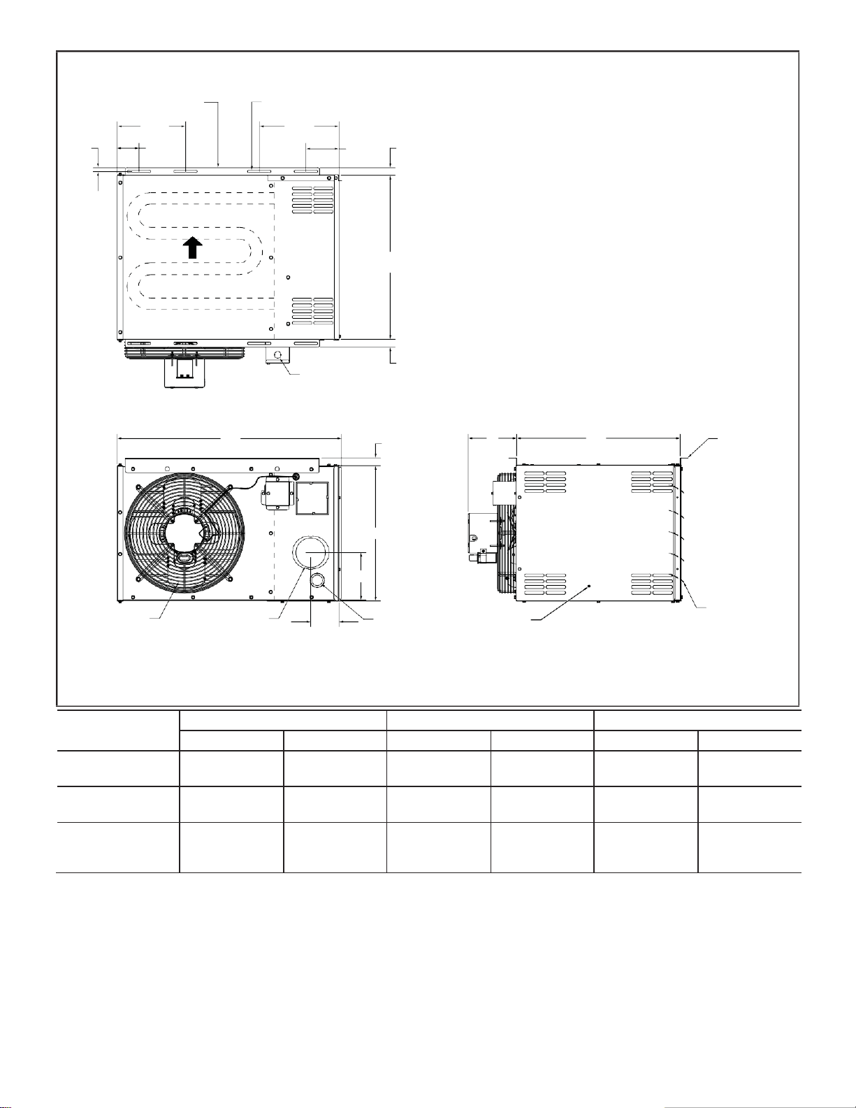
AIR
FLOW
21
(533)
HEAT EXCHANGER
TOP VIEW
ELECTRICAL
INLET
1
(25)
29
(737)
1
(25)
B
21
(533)
HANGING
BRACKETS (2)
A
C
DIRECT
DRIVE FAN
FLUE
OUTLET
BACK VIEW
3-5/8
(92)
GAS
INLET
SERVICE
ACCESS
PANEL
ADJUSTABLE
LOUVERS
Model
No.
A
B
C
in.
mm
in.
mm
in.
mm
UHRS-030A
UHRS-045A
12-3/8
314
6-1/2
165
3-7/8
98
UHRS-060A
UHRS-075A
17-1/2
445
6-1/4
159
6-1/8
156
UHRS-090A
UHRS-105A
23
584
7-7/8
200
9-1/8
232
1/2
[13]
UHRS-030 / 105 DIMENSIONS - Inches (mm)
MOUNTING SLOTS (Typical)
5/16 x 3Inches (8 x 76mm)
10-1/2
(267)
SIDE VIEW
1
(25)
4-1/4
(108)
HANGING
BRACKETS (2)
8-3/4
(222)
2-3/4
(70)
Page 3
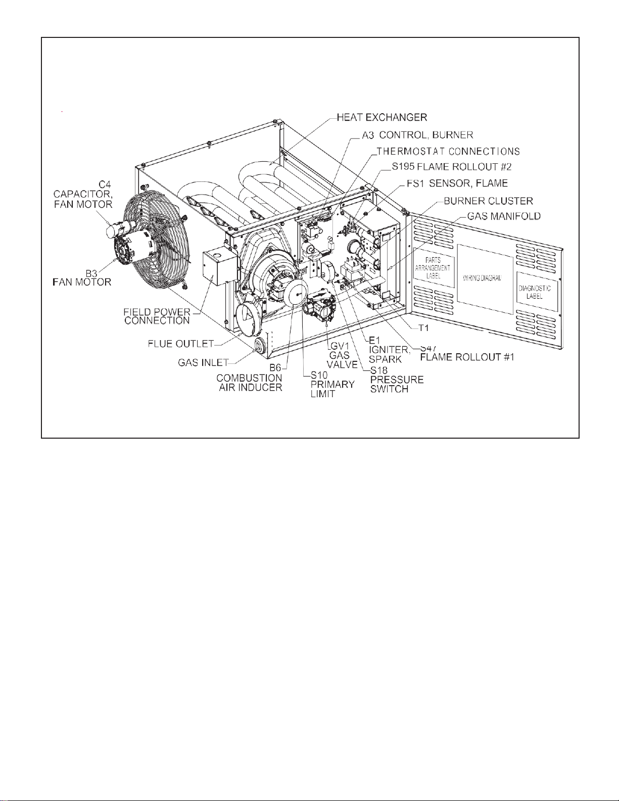
UHRS COMPACT UNIT HEATER PARTS ARRANGEMENT 030 /
105K BTUH
TRANSFORMER
Page 4
(137)
(267)
1/2 (13)
C
B
Model
No.
A
B
C
D
in.
mm
in.
mm
in.
mm
in.
mm
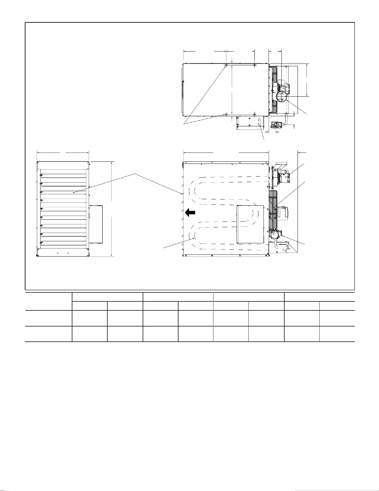
UHCM-125
UHCM-150
19-1/2
495
18-1/2
470
12-1/4
311
4-3/4
121
UHCM-175
UHCM-200
25
635
23-3/4
603
9-1/2
241
3
76
UHCM-125 / 200 DIMENSIONS -Inches (mm)
16 (406)
10-1/2 5-3/8 D
1/2 (13)
3-1/8 (79)
(4) 3/8-16 MOUNTING NUTS
FOR UNIT SUSPENSION
TOP VIEW
2-1/2 (64)
ELECTRICAL INLETS
ADJUSTABLE
LOUVERS
COMBUSTION AIR
INDUCER
FLUE OUTLET
A
31-7/8 (810)
10-5/8
(270)
DIRECT DRIVE FAN
35-1/4
(895)
AIR
FLOW
HEAT
EXCHANGER
GAS VALVE
FRONT VIEW
SIDE VIEW

Page 5
Model
No.
A
B
C
in.
mm
in.
mm
in.
mm
UHCM-250
UHCM-300
37-5/8
956
36-1/2
927
15-7/8
403
UHCM-350
UHCM-400
47
1194
45-3/4
1162
20-1/2
521
1/2 (13)
C
B
FLUE OUTLET
(4) 3/8-16 MOUNTINGNUTS
FOR UNIT SUSPENSION
1/2 (13)
3-1/8 (79)
DIRECT DRIVE FAN
35-1/4
(895)
AIR
FLOW
HEAT
EXCHANGER
GAS VALVE
FRONT VIEW
SIDE VIEW
10-5/8
(270) COMBUSTION AIR
INDUCER
ADJUSTABLE
LOUVERS
TOP VIEW
31-7/8 (810)
2-5/8 (67)
ELECTRICALINLETS
3
(76)
5-3/8
(137)
(267)
10-1/2
UHCM- 250 / 400 DIMENSIONS - Inches (mm)
16 (406)
A
Page 6
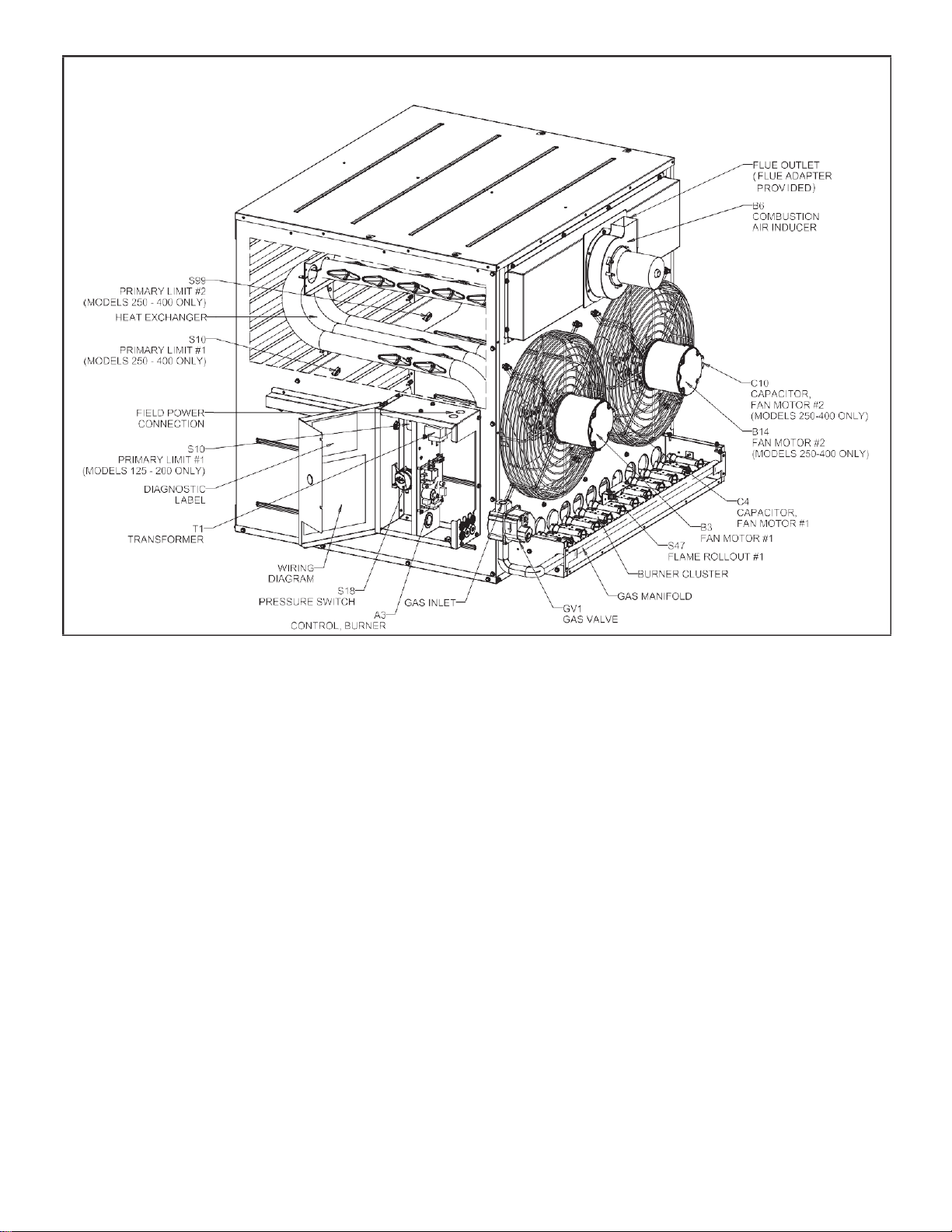
UHCM STANDARD UNIT HEATER PARTS ARRANGEMENT 125 /
400K BTUH

Page 7
Shipping contents includes heater, installation instruc-
tions,warrantycertificate,twomountingbrackets(shipped
loose in UH(RS,CM)-30/105 units), and a flue transition
(included in UH(RS,CM)-175/400 units only). The heater
is shipped completely assembled. Check the unitforship-
ping damage. The receiving party should contact thelast
carrier immediately if any shipping damage is found.
Units require a changeover kit when the unit is to beused
with Natural gas. The kit is ordered separately. See
Engineering Handbook.
Installation of gas unit heaters must conform with local
building codes or, in the absence oflocal codes, with the
current editionofANSIZ223.1, National Fuel Gas Code.
Installation inaircraft hangersmustbe inaccordance with
thecurrent edition of ANSI/NFPA No. 409, Standard for
Aircraft Hangers.
Installation in parking structures must be in accordance
with the current edition of ANSI/NFPA No. 88A, Standard
for Parking Structures.
Installation in repair garages must be in accordance with
the current edition of ANSI/NFPA No. 88B, Standard for
Repair Garages.
These units are approved for residential garage or non-
confined living space applications. For installation in a
residential garage or non-confined living space, unit must
be installed so that burners and ignition source are
located no less than 18” (457mm) above floor. Heater
must be located or protected to avoid physical damage
by vehicles. Referto the current edition of ANSI Z223.1,
National Fuel Gas Code.
Authorities having jurisdiction should be consulted before
installation. Airforcombustion and ventilation must con-
form tothemethods outlinedinthecurrent editionofANSI
Z223.1,Section5.3,AirforCombustionandVentilation,or
applicable provisions of local building codes.
The National Fuel Gas Code (ANSI Z223.1) is available
from:
American National Standard Institute Inc.
11 West 42nd Street
NewYork, NY 10036
These unit heaters are CSAInternational design-certified.
These unit heaters are certified for installation tocombus-
tible material as listed in Table1 and on unit rating plate.
Accessibility and service clearances must be observed in
addition to fire protection clearances.
All electrical wiring and grounding for unit must be in ac-
cordance with the regulations of the current edition of
ANSI/NFPA No. 70, National Electric Code.
The National Electric Code is available from:
National Fire Protection Association
1 Batterymarch Park
PO Box 9101
Quincy, MA 02269-9101
These instructions are intended only as a general guide
and do not supersede local codesin any way. Authorities
having jurisdictionshouldbeconsultedbeforeinstallation.
The installation must conform with localbuilding codes or,
in the absence oflocal codes, with the current edition of
CSA-B149installationcompliancecodes.Allelectricalwir-
ing and grounding for the unit must also comply with the
current edition of CSA C22.1, Canadian Electrical Code.
These unit heaters are CSA-certified for the installation
clearances listed on the rating plate and in table 1.
Adequate clearance must be provided around the appli-
ance and around air openings into the combustion cham-
ber. Provision shall be made for service accessibility.
NOTE - Fire protection clearances may be exceeded to
provide additional space for service and accessibility.
GARAGE/ WAREHOUSEINSTALLATIONS
1 - In a storage area, clearance from heaters to
combustible materials must be such that the
combustible material must not attain a temperature
above 160°F (71°C) by continuous operationofthe
unit.
WARNING
Combustible materials thatare affected by exposure to
temperatures LESS than 160°F (plastics, plastic wrap,
styrofoam, cardboard, etc.) must be stored well away
from this heater. Discharge air temperatures for these
units can approach 200°F.
2 - Maintain an 8-foot (2m) minimumclearance from the
floor to the bottom of the heater. Refer to the current
edition of CSA-B149 for installation compliance
codes. AIRCRAFT HANGER
1 - In an area where aircraft are housed or serviced, a
10-foot (3m) minimum clearance from the highest
surface ofthe aircraft to bottom of the heater must
be maintained.
2 - In other areas, an 8-foot (2m) minimum clearance
from the floor to bottom ofheater must be maintained.
3 - Heatersshould belocated sothat theyare protected
fromdamagefromaircraftorotherappliancesneeded
for servicingof aircraft. Referto requirements of the
enforcing authorities.
RESIDENTIAL
These units are approved for residential garage or non-
confined living space applications. For installation in a
residential garage or non-confined living space, unit must
be installed so that burners and ignition source are
located no less than 18” (457mm) above floor. Heater
mustbe locatedor protectedtoavoidphysical damageby
vehicles. Referto the current edition of CSA-B149 for in-
stallation compliance codes.In a confined area, the heat-
er must be installed inaccordance with the current edition
of CSA-B149 installation compliance codes. Be sure to
check withlocal codes and ordinances for additional re-
quirements.
Optional Accessory
Requirementsin USA
Requirementsin Canada
Shipping
Page 8
TABLE 1
UNIT CLEARANCES TO COMBUSTIBLE MATERIALS
Unit
Top
Side**
Bottom
Back
Flue
in
mm
in
mm
in
mm
in
mm
in
mm
030/105
1
25
1
25
1
25
18
457
6*
152
125/400
6
152
18
457
1
25
18
457
6
152
*6” is for single wall. Double wall B-vent clearancewill be
in accordance with the manufacturer’s listing.
**Accesspanel or controlbox side ofunit should have 24”
(610mm) clearance.
The Commonwealth ofMassachusetts stipulates the fol-
lowing additional requirements:
1 - Gas furnaces shall be installed by a licensed
plumber orgas fitteronly.
2 - The gas cock must be “T handle” type.
The appliance shall not be installed downstream from
evaporator coils or cooling units.
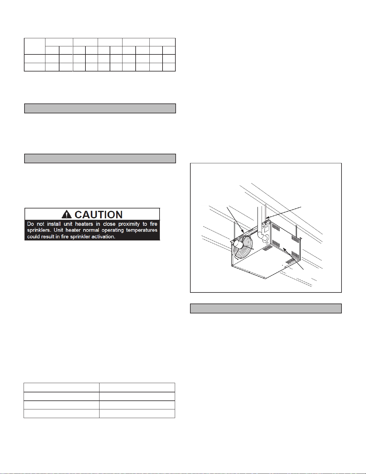
Install the unit in the desired location as governed by
clearances, vent connection, air direction, gas supply,
electrical supply and service accessibility.
Unit is shippedready forinstallation.
UHCM -125/400 UNITS
Four mounting nuts are furnished. Refer to dimension
illustration. Mounting nuts will accommodate 3/8” x 16
threaded rods.
1 - Push each louver to the left to depress spring and
release locking tab on the other end (locking tab
keeps the louver in place for shipping).
2 - Rotate louvers to direct airflow as desired.
3- Cut threaded rods to desired length and slide a 3/8”
nut onto the rod.
4 - Slide a flat washer onto the threaded rodAFTER the
nut (7/16” inside diameter X 1” outside diameter X
1/16” thick washer).
5 - Screwtherods (two or four) into the mounting nuts
on the unit.
6 - Tighten nuts to secure unit to rods.
TABLE 2
MAXIMUM MOUNTING HEIGHTS - 125/400
UHRS 30/105
Unit may be installed as shown in figure 1 or rotated
180°.
1 - Push each louver to the right to depress spring and
release locking tab on the other end (locking tab
keeps the louver in place for shipping).
2 - If installing unit in a rotated position - release locking
tabs in the same manner as previous step. Rotate
each louver 180° and reinstall. Remove and retain
screws securing access panel. Rotate accesspanel
180° and resecure using retained screws.
3 - Rotate louvers to direct airflow as desired.
4 - Choose location for mounting brackets.
5 - Alignmountingbracketswithpilotholes onthetop or
bottom (when rotating) edge ofthe unit. Secure with
screws provided in bag assembly.
6 - Tosupport unit, secure mounting bracket to ceiling
joist or truss. Unit may also be supported using
support rods as shown in figure 1.
INSTALL UNIT HEATER
(030 / 105 SHOWN)
MOUNTING
BRACKETS
(2) SUPPORT
RODS
ACCESS PANEL
FIGURE 1
Adequate facilities for supplying air for combustion and
ventilation must be provided in accordance with the cur-
rent edition of ANSI Z223.1, section 5.3 and CSA-B149
installation compliance codes,or applicable provisions of
local building codes.
All gas-fired appliances require air to be used for com-
bustion. In many buildings today, there is a negative in-
door air pressure caused by exhaustfans,etc.If sufficient
quantities ofcombustion air are not available, the heater
AdditionalRequirements
Unit Heater Installation
Combustion and Ventilation Air
Unit
Feet (Meters)
UHCM-125/150
16 (4.9)
UHCM-175/200
20 (6.1)
UHCM- 250/400
30 (9.1)
Page 9
or another appliance will operate in an inefficient manner,
resulting in incomplete combustion which can result inthe
production of excessive carbon monoxide.
If indoor air is to be used for combustion, it must be
free of the following substances or the life of the heat
exchanger will be adversely affected: chlorine, car-
bon tetrachloride, cleaning solvent, halogen refriger-
ants, acids,cements and glues, printing inks, fluorides,
paint removers, varnishes, or any other corrosives.
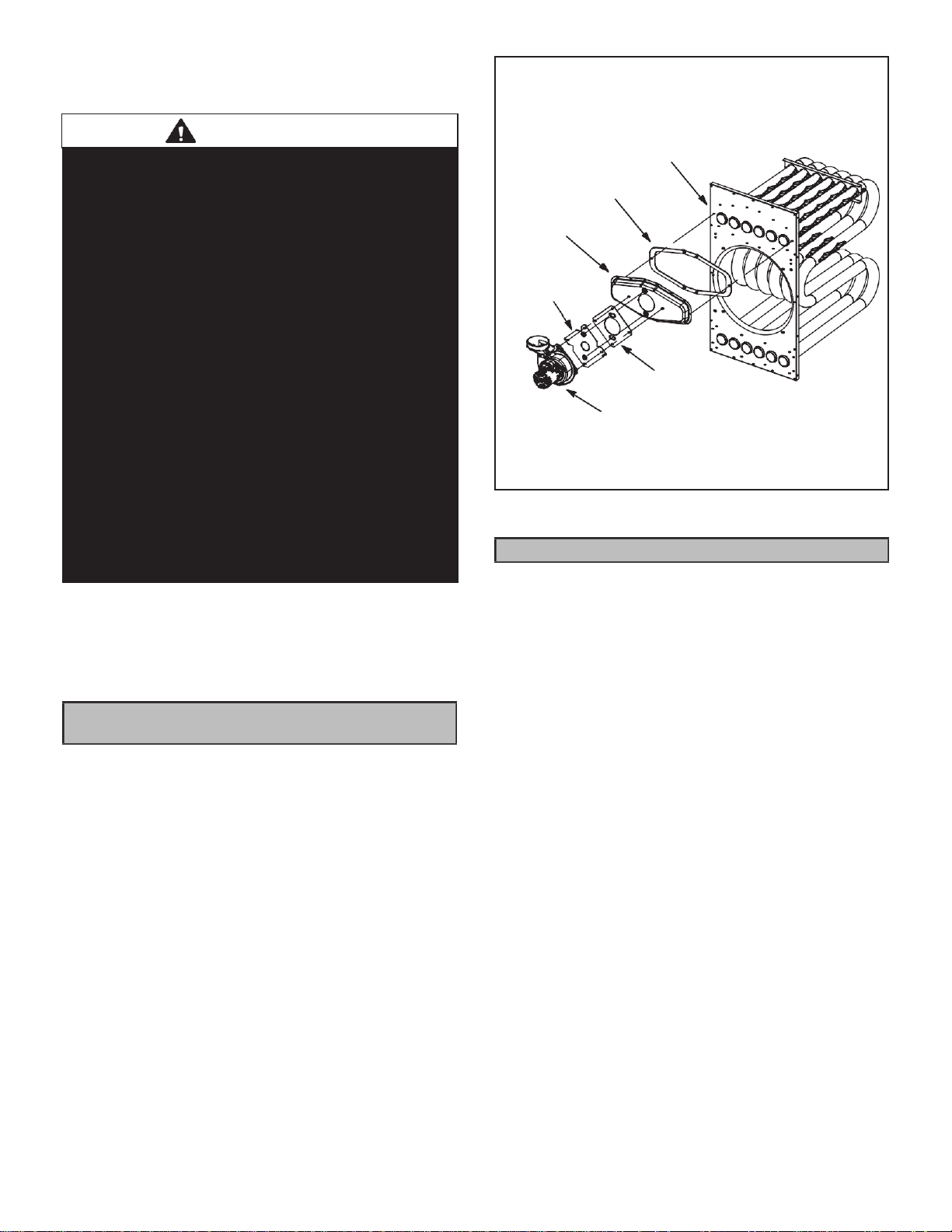
Rotation of Combustion Air Inducer (UHCM) -125 & 150
Only)
The combustion air inducer on UHCM -125 & 150 may
be rotated 90° either to the left or right of the original
vertical position in order to better suit the application.
NOTE - It is not permissible to rotate the combustion air
inducer on UHRS -030/105 and UHCM -175/400.
Rotate the combustion air inducer assembly as follows:
1 - Remove the heater from the carton. Decide the best
unit heaterorientation. The vent can be installed in
one of three discharge positions: up, left, orright.
2 - If the inducer is to be rotated, follow the instructions
in this section; otherwise, referto instructions under
“Venting” section.
3 - Before making an electricalorgas connections, use
a socket toremove the four screws which secure the
combustion air inducerto the flue box.See figure 2.
4 - Rotate the inducer 90° to the desired position.
Reinsert and tighten the inducer securing screws.
5 - The unit heater is now ready for installation as
described in the Venting section.
Venting
NOTE - The vent is a passageway, vertical or nearly so,
used to convey flue gases from an appliance, or its vent
connector,totheoutsideatmosphere. Theventconnector
is the pipe orduct that connects a fuel-gas-burning appli-
ance to a vent or chimney.
NOTE - Local codes may supersede any of these provisions.
GENERAL RECOMMENDATIONS AND
REQUIREMENTS
Unit heaters must be vented in compliance with the lat-
est edition of the National Fuel Gas Code (NFPA 54 /
ANSI Z223.1) in the USA and with CSA-B149.1 codes in
Canada, as well as applicableprovisions oflocal building
codes, and the following instructions.
030-150 Units - The transitionisa part of the combus-
tion air blower.
175-400 Units - A stamped/extruded metal transition
issuppliedwiththiscertifiedunit. Itmustnot be mod-
ified or altered and must be installed on the outlet
of the combustion air inducer assembly prior to the
installation of the vent connector.Failure to comply
with thisrequirement willvoidthe certification of the
unit by the approval agencies.
A single-wall vent connector may be used between the
furnace and the vertical vent pipe in all applications;how-
ever, single-wall vent material cannot be used for
vertical vent piping inresidentialapplications. UL-ap-
proved Category IIIventing materials must be used
in all residentialapplicationswhich venthorizontally.
WARNING
Insufficient combustion air can cause headaches,
nausea, dizziness or asphyxiation. It will also cause
excess water in the heat exchanger resulting in rusting
and premature heat exchanger failure. Excessive
exposure to contaminated combustion air will result
in safety and performance related problems. Avoid
exposure to the following substancesin the combustion
air supply:
Permanent wave solutions
Chlorinated waxes and cleaners
Chlorine base swimming pool chemicals
Water softening chemicals
De-icing salts or chemicals
Carbon tetrachloride
Halogen type refrigerants
Cleaning solvents (such as perchloroethylene)
Printinginks, paintremovers, varnishes, etc.
Hydrochloric acid
Cements and glues
Antistatic fabric softeners forclothesdryers
Masonry acid washing materials
FLUEBOX AND COMBUSTION AIR
INDUCER ASSEMBLY
125/150
VEST PANEL
FLUE BOX
GASKET
FLUE BOX
ORIFICE
PLATE
ORIFICE
PLATEGASKET
COMBUSTION
AIR INDUCER
FIGURE 2
Page 10
A single-wall vent pipe used as a vent connector in resi-
dential or commercial applications, oras a vertical vent in
commercial applications, musthave all seams and joints
sealed with pressure-sensitive aluminum tape or silicone
rubber sealant. Aluminumtapemust meetthe provisions
of SMACNAAFTS-100-73 Standards.The aluminum tape
must have a temperatureratingof400°F(204°C). Silicone
rubber sealant must have a temperature rating of 482°F
(250°C), i.e., Dow Corning RTV-736 or equivalent. All
jointsmustbesecuredwithatleasttwocorrosion-resistant
screws. All joints must be checked for gas tightness after
installation. Single-wallvent pipe used as vertical vent in
commercial applicationsmust not pass through anyattic,
interior wall, concealed space, or floor.
VERTICAL VENTS USING METAL VENT PIPE -
COMMERCIAL AND RESIDENTIAL INSTALLATIONS
These compact unit heaters are listed as Category 1
appliances for vertical vent installations.
1 - These unit heaters are to be used with NFPA- or
ANSI-approved chimneys or U.L.-listed type B-1
gas vents, orlisted chimney lining systems for gas
ventingwhere applicable,aswellas themodifications
and limitationslistedinfigure3. Sealsingle-wall vent
material according to General Recommendations
and Requirements section.
2 - The vent connector shall be 4” (102mm) diameter
on 30K, 45K, 60K, 75K,090,105K, 125K,and 150K
Btuh
units; 5” (127mm) diameter on 175K, 200K, 250K,
& 300K Btuh units; 6” (152mm) on 360 & 400K Btuh
units. On 175-400 units, a flue transition piece
(supplied) is required to fit over the outlet of the
induced draft assembly on the appliance.
NOTE - If needed, loosen the upper right two or three
screws securing thecombustion air blower. Slide thetran-
sition into place and secure loosened screws.
3 - Keepthevent connector runs as short as possible
with a minimum number of elbows. Refer to the
current edition of ANSI Z223.1 or CSA-B149
installationcompliance codes for maximum ventand
vent connector lengths.
4 - The entirelengthofasingle-wallmetalventconnector
shall be readily accessible for inspection, cleaning
and replacement.
5 - Single-wall vent pipe used as vertical vent in
commercial applicationsmust not pass through any
attic, interior wall, concealed space, or floor.
TABLE 3
MAXIMUM HORIZONTAL VENT CONNECTOR AND
HORIZONTAL VENT PIPE LENGTHS
No. of
Elbows
30, 45,60, 75,090, 105,
100,115, 145, 175, 200,
360, 400
250 & 300
ft
m
ft
m
1
25
7.6
35
10.7
2
20
6.1
30
9.1
3
15
4.6
25
7.6
4
10
3.0
20
6.1
5
5
1.5
15
4.6
6
-
-
10
3.0
7
-
-
5
1.5
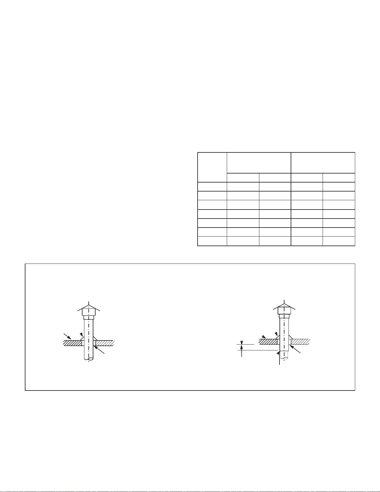
VENT TERMINATION ON SINGLE-WALL VERTICAL VENT RUNS
Commercial Application Only
SINGLE-WALL VENTPIPE WITH SINGLE-WALL VENT PIPE WITH
SINGLE-WALL TERMINATION DOUBLE-WALL (TYPE B-1) TERMINATION
ROOF FLASHING ROOF FLASHING
ROOF PITCHED
ROOF PITCHED FROM 0” TO 45”
FROM 0” TO 45”
12”MAX CLEARANCE TO BE
2” CLEARANCE AS SPECIFIED ON
THIMBLE TYPE “B” VENT PIPE.
SEAL JOINT BETWEENSINGLE-WALL VENT AND “B” VENT TERMINATION
AND THE OPEN SPACE BETWEEN THE SINGLE WALL VENT PIPE AND
THE OUTER PIPE OF THE “B” VENT TERMINATION.
FIGURE 3

Page 11
6 - The unit may beventedverticallyasasingleappliance
or ina common vent with other gas-fired appliances.
In common venting situations, vent connectors for
otherappliancesmustmaintaina4” (102mm)vertical
separation between the vent connectors. Refer to
common venting tables in the current editions of
ANSIZ223.1 or CSA-B149 installation compliance
codes for proper vent size.
7 - Clearance to combustible material is 6” (152mm)
for single-wall vent material except where a listed
clearance thimble is used. Clearance tocombustible
material for type B-1 vent or factory-built chimneyis
per manufacturer’s instructions.
8 - The vent connector shall be supported without any
dips or sags. Vertical vents shall be supported in
accordance with their listing and manufacturers’
instructions. All horizontal vent connectorruns shall
have a slope up to the vertical vent of at least 1/4”
per foot (1mm per 50mm).
9 - All vertical type B-1 vents, single-wall vertical vents
(commercial applications), or listed chimney lining
systemsmustbeterminatedwithaUL-listed(orother
equivalent agency) vent cap orlisted roofassembly.
10- The vent must extend at least 3 feet (1m) above
the highest point where it passes through a roof
of a building. The vent must also extend at least 2
feet (1m)higher thanany part of a building within a
horizontal distance of10 feet (3m) unless otherwise
specified by ANSI Z223.1 or CSA-B149 installation
compliance codes. Thevent must extend at least 5
feet (2m) above the highest connected equipment
flue collar HORIZONTAL VENTING
NOTE - Commonventingisnot allowed when horizontally
venting the unit heater.
If the UH(RS,CM) unit heater is to be horizontally vented,
a positive pressure may be created in the vent. The unit
heater,wheninstalled withhorizontal venting,will perform
as a category III appliance.
1 - In residential applications which vent horizontally,
use only special vent materials approved for use
with Category III appliances.
2 - The vent pipe diameter for horizontal installations
shall be 4” (102mm) diameter on 30K, 45K, 60K,
75K, 090, 105K, 125K, and 150K Btuh units; 5”
(127mm) diameter on 175K, 200K, 250K, & 300K
Btuh units; 6” (152mm) on 350 & 400K Btuh units.
On175-400units, a flue transition piece (supplied)
is required to fit over the outlet of the induced draft
assembly on the appliance.
3 - The minimum horizontal vent length is 5 feet (2m).
4 - Refer totable3for maximumhorizontalventlengths.
5 - If possible, do not terminate the horizontal vent
through a wall that is exposed to prevailing wind.
Exposure to excessive winds can affect unit
performance. If such a termination is necessary,use
a wind block to protect the vent termination from
direct winds.
6 - Horizontal vent termination must be free from
obstructions and at least 12” (305mm) above grade
level and maximum snow height.
7 - Do not install a horizontal vent termination directly
below roof eaves or above a public walkway, or
any other area where condensate dripping may be
troublesome and may cause some staining. Avoid
windows where steam may cause fogging or ice
buildup.
8 - Minimum clearance for horizontal vent termination
from any door, window, gravity air inlet, gas or
electric meter,regulators, and relief equipment is 4
feet (1m) for United States installations. In Canada,
horizontal vent termination must have a minimum 6-
foot horizontal clearance from gas and electric
meters and relief devices.
Refer tolatesteditionsoftheANSIZ223.1orCSA-B149
forinstallationcompliancecodesandwithlocalauthor-
ities with jurisdiction.
9 - Vent termination must be a minimum of 4 feet (1m)
below, or4feet (1m) horizontally, from any soffit or
under-eave vent.
10 - Vent must be a minimum of 6 feet (2m) from an
inside corner formed by two exterior walls. If
possible, leave a 10-foot (3m) clearance.
11- Ventterminationmustbeaminimumof10feet (3m)
from any forcedair inlet (includes fresh air inlet for
other appliances, such as a dryer).
12 - When termination is routed through combustible
wall, vent termination must be supported using a
firestop to maintain clearances specified on unit
rating plate. Inside edge of vent termination must
be at least 16” (406mm) from outside wall
13 - All horizontal vents which use special vent pipe for
use with Category III appliances must terminate
with an approved Category III tee. Opening end
must face downward.
14 - For horizontal venting, the vent pipe shall be
supported with hangers no more than 3 feet (1m)
apart to prevent movement after installation.
15 - Selectawallterminationpointthatwillmaintain1/4”
(6mm)riseper foot(305mm)slopeofhorizontalrun
of vent pipe.
16 - For upward sloped vent, a condensate tee and
drain must be installed within the first 5 feet (2m)
from the unit heater to protect the appliance. If a
flexible condensate drain line is used, the drain
line must include a loop filled with water to prevent
combustion products from entering the structure. If
the unit is shut down for an extended period oftime
and will be exposed to sub-freezing temperatures,
the condensate may freeze.
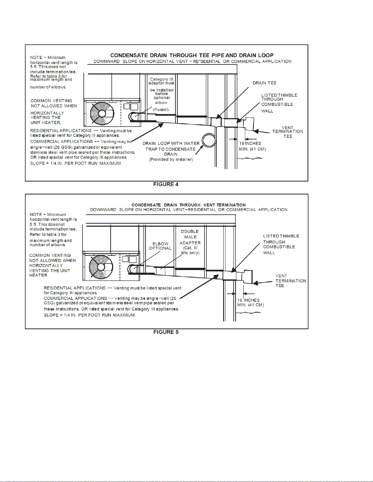
17 - Selectawallterminationpointthatwillmaintain1/4”
rise per foot slope of horizontal run of vent pipe. In
areas where authorities having jurisdiction permit,
a downward slope of maximum 1/4” per foot is also
acceptable. Condensate drainage can be collected
ina teepipesection(figure4)withdrain loopsimilar
to one used for upward slope vent, or allowed to
drip through the vent termination, if permitted by
authorities (figure 5).
Page 12

Page 13
FIGURE 6
TABLE 4
Category III Horizontal Venting Components²
(Required for Horizontal Vent Applications)
UH(RS,CM) Unit
Vent
Diameter (in.)
Upslope Vent
Kit / Cat. No.
Downslope Vent
Kit / Cat. No.
45° Elbow Kit /
Cat. No. (optional)
90° Elbow Kit /
Cat. No. (optional)
¹Min. Vent Length
(ft.)
30, 40, 45, 60, 75,
90, 105, 125, 150
4
C5VENT4KU /
75W63
C5VENT4KD /
75W67
C5VENT4E45 /
87W80
C5VENT4E /
75W71
5
175, 200, 250,
300
5
C5VENT5KU /
75W64
C5VENT5KD /
75W68
C5VENT5E45 /
87W81
C5VENT5E /
75W72
350, 400
6
C5VENT6KU /
75W65
C5VENT6KD /
75W69
C5VENT5645 /
87W82
C5VENT6E /
75W73
¹Length doesnot include termination (orelbowwhere applicable).
NOTE - Elbowisrequired where shown to facilitate connection of horizontalvent kit to flue outlet.
²Referto EHB forvent pipe part numbers.
VENTING USING A MASONRYCHIMNEY
The following additional requirements apply when a lined
masonry chimneyis being used to vent the compact unit
heater.
IMPORTANT
Single appliance venting of a fan-assisted unit heater
intoatilelinedmasonrychimney(interiororoutsidewall)
is prohibited. The chimney mustfirst be lined witheither
type “B-1“ vent or an insulated single-wall flexible vent
lining system, sized in accordance with venting tables in
the ANSI Z223.1, or CSA-B149 installation compliance
codes.
1 - Masonry chimneys used to vent Category I units
heatersmustbeeithertile-linedorlinedwitha listed
metal lining systemor dedicated gas vent. Unlined
masonry chimneys are prohibited. A category I
appliance must never be connected to a chimney
that is servicing a solid fuel appliance. If a fireplace
chimney flue is used to vent this appliance, the
fireplace opening must be permanently sealed.
2 - A fan-assisted unit heater maybe commonlyvented
into an existing lined masonry chimney provided:
a. The chimney is currently serving at least one draft-hood
equipped appliance.
b. The vent connector and chimney are sized in accordance
with venting tables.
3 - A “B1” double-wall vent or masonry chimney liner
shall terminate above the roof surface with a listed
cap or a listed roof assembly in accordance with
the terms of their respective listings and the vent
manufacturer’s instructions.
4 - Do not install a manual damper, barometric draft
regulator, or flue restrictor between the unit heater
and the chimney.
5 - If type“B1” double-wallventisusedinsideachimney,
no otherappliance can be vented into the chimney.
Outer wall oftype “B” vent pipe must not be exposed
to flue products.
6 - Insulation for the flexible vent pipe must be an
encapsulated fiberglass sleeve recommended by
the flexible vent pipe manufacturer.
7 - The space between liner and chimney wall should
NOTbeinsulatedwithpuffedmicaorany other loose
granular insulating material.
16 INCHES
MIN. (41 CM)
VENT
TEE
RESIDENTIALAPPLICATIONS −− Venting must be listed special vent
for Category III appliances.
COMMERCIAL APPLICATIONS −− Venting may be single−wall (26
GSG) galvanized or equivalent stainless steel vent pipe sealed per
these instructions, OR listed special vent for Category III appliances.
SLOPE = 1/4 IN. PER FOOT RUN MAXIMUM.
LISTED THIMBLE
THROUGH
COMBUSTIBLE
WALL
(Cat. III
kits only)
COMMON VENTING
NOT ALLOWED WHEN
HORIZONTALLY
VENTING THE UNIT
HEATER.
ELBOW
MALE
NOTE − Minimum
horizontal vent length is
5 ft. This does not
include terminationtee.
Refer to table 3 for
maximum length and
number of elbows.
CONDENSATE DRAIN THROUGH VENT TERMINATION
DOWNWARD SLOPE ON HORIZONTALVENT−RESIDENTIAL OR COMMERCIAL APPLICATION
Page 14
8 - If B-1 vent or an insulated flexible vent pipe cannot
be used as liners, the chimney must be rebuilt
to accommodate one of these methods or some
alternateapproved methodmust befoundtovent the
appliance. When inspection reveals that an existing
chimney is not safe for the intended purpose, it
shall be rebuilt to conform to nationally recognized
standards, lined or relined with suitable materials
or replacedwith a gas vent or chimney suitable for
venting unit heaters. Thechimney passagewaymust
be checked periodically to ensure that it is clear and
free of obstructions.
REMOVAL OF UNIT FROM COMMON VENT
In the event that an existing unit heateris removed from a
venting systemcommonlyrunwithseparategas applianc-
es, the venting systemis likely to be too large to properly
vent theremainingattachedappliances.Thefollowingtest
should be conducted while each appliance isin operation
and the other appliances are not in operation, yet remain
connected to the common venting system. If the venting
system has been installed improperly, the systemmust be
corrected.
1 - Seal any unused openings in the common venting
system.
2 - Visually inspecttheventingsystemforpropersizeand
horizontal pitch. Determine there is no blockage or
restriction, leakage,corrosion, or other deficiencies
which could cause an unsafe condition.
3 - In so far as is practical, close all building doors and
windows andall doors between the space in which
the appliances remaining connected to the common
venting systemare located and other spaces of the
building. Turn on clothes dryersand any appliances
not connected to the common venting system. Turn
on any exhaust fans, such as range hoods and
bathroomexhausts,sotheywilloperateatmaximum
speed. Do not operate a summer exhaust fan. Close
fireplace dampers.
4 - Followthe lighting instructions. Place the appliance
being inspected in operation. Adjust thermostat so
appliance will operate continuously.
5 - Test for spillage at the draft hood reliefopening after
five minutes ofmain burner operation. Use the flame
of a match or candle, or smoke from a cigarette,
cigar, or pipe.
6 - After it has been determined that each appliance
remaining connected to the common venting system
properly vents when tested as outlined above, return
doors, windows, exhaust fans, fireplace dampers
andany othergas-burningappliancetotheirprevious
condition of use.
7 - If improperventing isobserved during any of the above
tests, the common venting systemmust be corrected.
The common venting system should be resized to ap-
proach the minimum size as determined by using the
appropriatetablesinAppendixGinthecurrenteditions
of theANSIZ223-1, or the appropriate Category I Nat-
ural Gas and Propane appliances venting sizing tables
in the current standards of the CSA-B149 for installa-
tion compliance codes.
NOTE - Local codes maysupersede anyofthe provisions
outlined in this instruction.
The UH(RS,CM) series unit heaters use a direct spark
ignition system. There is no pilot necessary as the spark
lights the main burner as the gas valve is turned on. The
direct spark ignition controlboard emits radio noise asthe
sparkingprocessis under way. The level of energy may
be sufficient to disturb a logic circuitin a microprocessor
controlled thermostat. It is recommended that an isola-
tion relay be used when connecting the unit heaters to a
microprocessor controlled thermostat. Install the thermo-
stat accordingto instructionsprovided. Install a separate
fused disconnect switch, with the fuse sized according to
blower motor size. Connect wiring through knockout on
the junction box located on the side ofthe unit heater. Re-
fertodimensions inthefrontof thisinstructionforlocation.
Refertoheaterwiring diagramfor connectioninformation.
Use18 gauge wire or larger for thermostat connections.
NOTE - Electricallyground unit in accordance with local
codes or, in the absence of local codes, in accordance
with thecurrent editions of the ANSI/NFPA No. 70, Na-
tional Electrical Code orCSA C22.1,Canadian Electrical
Code, Part 1.
NOTE - Uninsulated ground wires must be wrapped in
electrical tape to avoid damage to the electrical system.
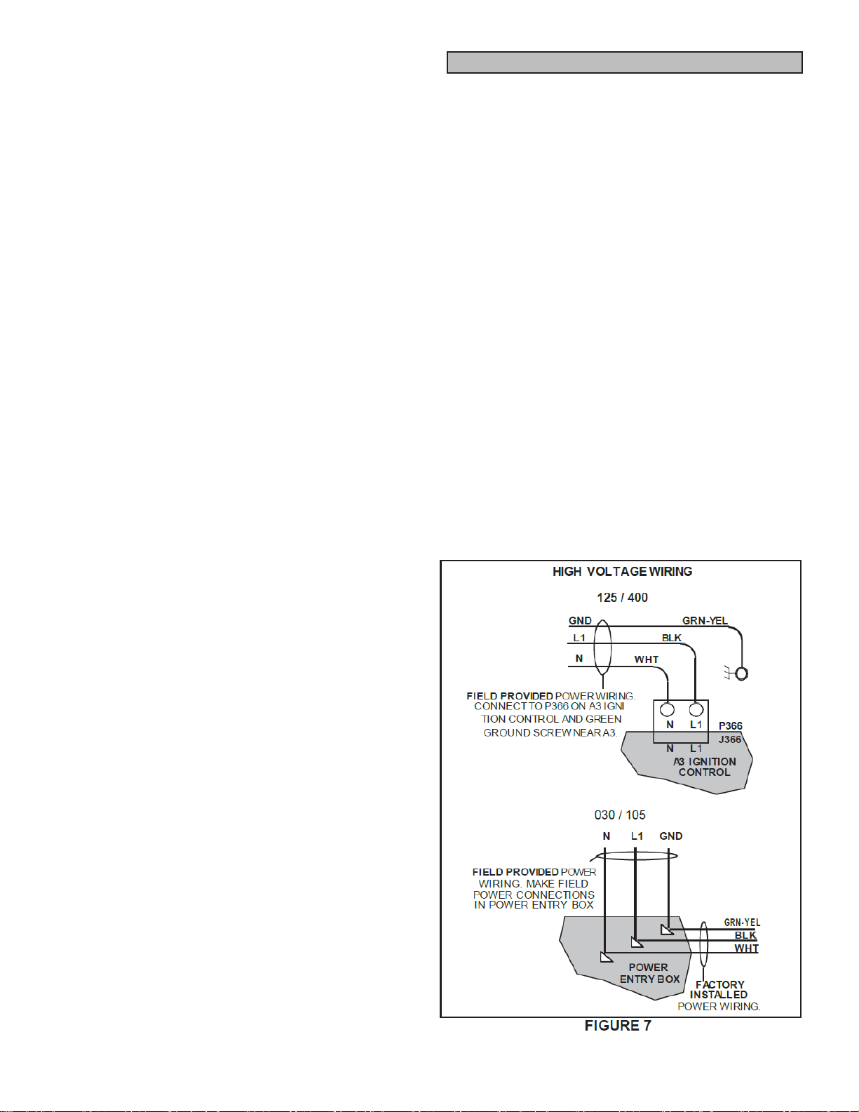
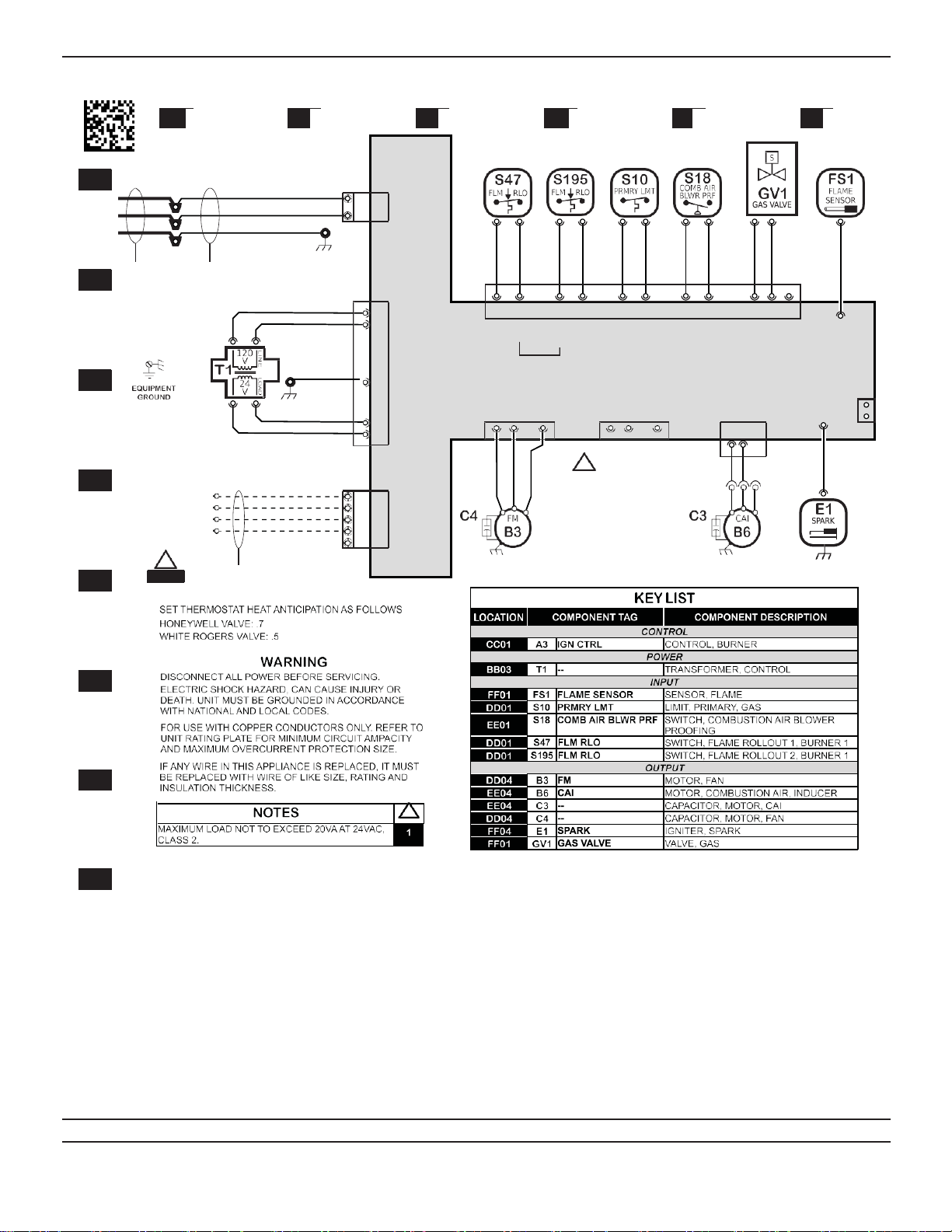
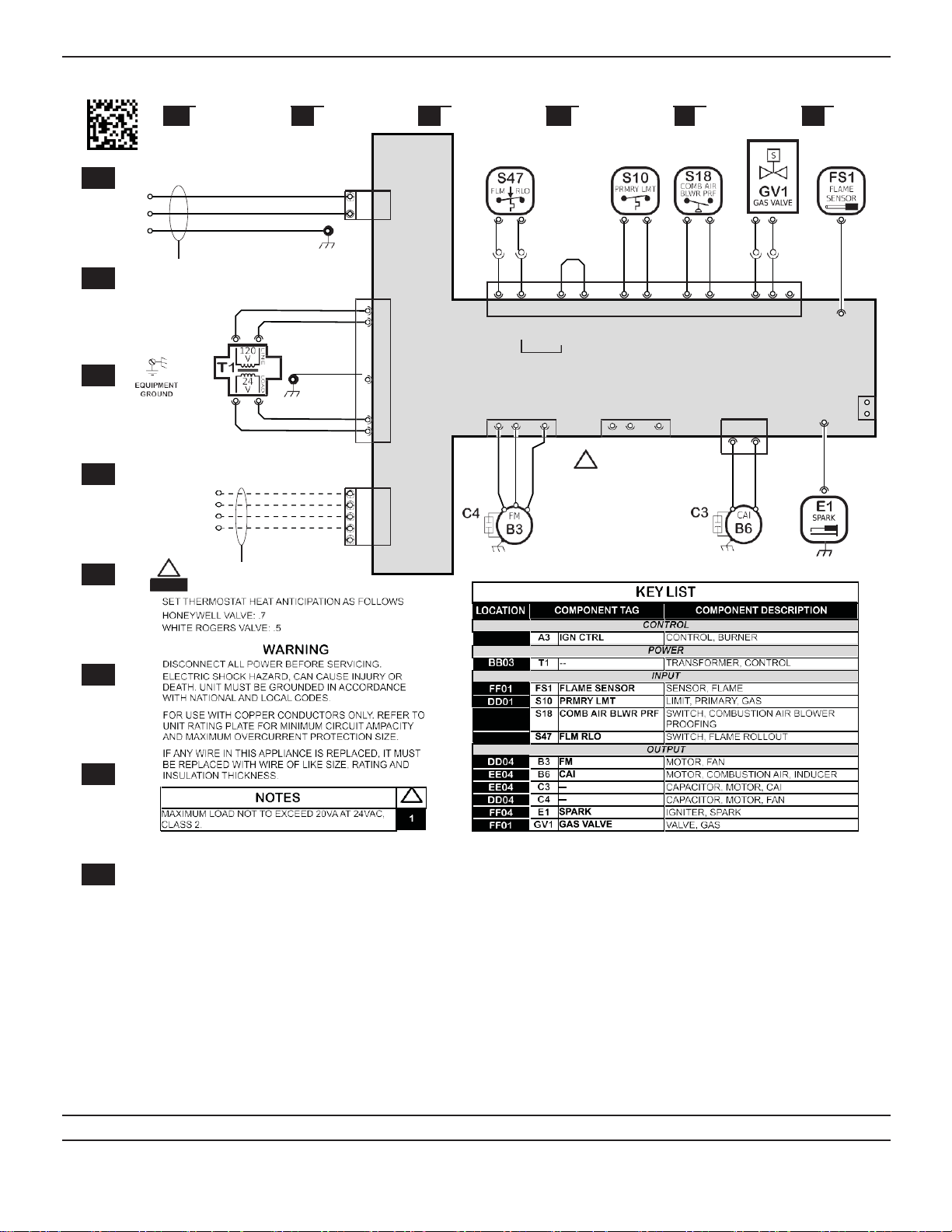
Make line voltage connectionsas shown in figure 7. Con-
nect field wiring as shown on wiring diagram on unit. Also
refer to typical diagram in this manual.An additional ther-
mostat wire must be run to terminal “G” on heater when
continuous blower is desired.
Electrical Connections
Page 15
P19 J19
WHT WHT
BLK BLK
FAC RUN TEST
5
537992-01
AA BB CC DD EE FF
A3
HIGH VOLTAGE POWER CONNECTIONS I GN CTRL
L1
N
GND
BLK
WHT
GRN- YEL
L1 L1
N N
NO COM
FIELD PROVIDED
POWER WIRING.
MAKE FIELD POWER
CONNECTIONS IN
POWER ENTRY BOX.
FACTORY INSTALLED POWER
WIRING
BLK
1 1 XFMR- L1
3 3 XFMR- N
P368 8 2 7 1
J368 8 2 7 1
9 3 5 4
9 3 5 4
11 6
11
12
6 12
GRN- YEL 4 4
GND WIRE
ATTACHED TO
XFMR MOUNTI NG
GND- BOARD P373
1
SCREW 5 XFMR- COM
6P364 P365 2
J 374 4 1
BLU 6 XFMR- 24VAC 2 5 8 2 5 8
LOW VOLTAGE THERMOSTAT CONNECTIONS
24V POWER (R) R R
24V COMMON (C) C C
P365 AND P364
ARE ENERGIZED
SIMULT A N E O U SL Y
P374 4 1
1 3
BLOWER (G) G G
HEAT (W1) W1 W1
W2 W2
FIELD PROVIDED
CLASS II 24VAC
THERMOSTAT WIRING
Model: UHRS Unit Heater; SeparatedCombustion Unit Heater Heat Input -
030k-105k BTUH
Voltage: 120/60/1
Supersedes: N/A Form No: 537992-01 Rev: 0
06
07
08
05
04
YEL
03
WHT
02
01
0
CO
P366
J 366
P367
J367
P363
J 363
WHT
GRN- YEL
BLK
WHT
S47
FAN1- N
FAN1- GND
24VAC-IN
WHT
S47
FAN1- L1
WHT
S195
WHT
S195
- OUT
FAN2- N
FAN2- GND
BLU
S10
24VAC-IN
BLU
S10
- OUT
FAN2- L1
PNK
S18
24VAC-IN
BRN
S18
- OUT
CA I - N
CA I - L1
COM
M
GRY
WHT
GV-C
GV- M
GV- H
RED
GRY
SPARK
FLA ME SENS
WHT- RED
!
1
Page 16
FAC RUN TEST
538025-01
AA BB CC DD EE FF
A3
HI GH VOLTAGE POWERCONNECTI ONS I GN CTRL
L1
N
GND
BLK
WHT
GRN- YEL
FIELD PROVIDED POWER WIRING.
CONNECT TO P366 AND GREEN GROUND
SCREW LOCATED INSIDE UNIT.
L1 L1
N N
1 2
1 2 WHT
NO COM
3 4
3 4
BLK 1 1 XFMR- L1
3 3 XFMR- N
P368 8 2
J368 8 2
7 1 9 3 5 4
7 1 9 3 5 4
11 6
11
12
6 12
GRN-YEL 4 4
GND WIRE
ATTACHED TO
XFMR MOUNTING
GND- BOARD P373
1
BLU
SCREW 5 5 XFMR- COM
6 6 XFMR- 24VAC P364 25 8 P365 2
2
5 8 J374 1 4
LOW VOLTAGE THERMOSTAT CONNECTIONS
24V POWER (R)
24V COMMON (C)
BLOWER (G)
HEAT (W1)
R R
C C
G G
W1 W1
W2 W2
P365 AND P364
ARE ENERGIZED
SIMULT A N E O U SL Y
P374 1 4
FIELD PROVIDED
CLASS II 24VAC
THERMOSTAT WIRING
Model: UHRS Unit Heater; SeparatedCombustion Unit Heater Heat Input -
125k-200k BTUH
Supersedes: N/A Form No: 538025-01 Rev: 0
02
120/60/1
Voltage:
08
07
06
05
04
03
01
YEL
WHT
0
P366
J 366
P367
J367
P363
J 363
WHT
WHT
S47
FAN1- N
FAN1- GND
24VAC-I N
GRN- YEL
WHT
S47
BLK
FAN1- L1
S195
S195
- OUT
FAN2- N
FAN2- GND
S10
BLU
24VAC-I N
BLU
S10
- OUT
FAN2- L1
PNK
S18
24VAC-I N
BRN
S18
- OUT
BLK
CA I - L1
COM
M
WHT
GRY
WHT
CA I - N
GV-C
GV- M
GV- H
GRY
SPARK
FLA ME SENS
WHT- RED
!
1

Page 17
FAC RUN TEST
5
AA BB CC DD EE FF
A3
538024-01
L1
N
GND
HIGH VOLTAGE POWER CONNECTIONS
BLK L1
WHT N
GRN- YEL
FIELD PROVIDED POWER WIRING.
CONNECT TO P366 AND GREEN GROUND
SCREW LOCATED INSIDE UNIT.
I GN CTRL
L1
N
1 2
1 2
BLU
BLU
NO COM
3 4 5
3 4 5
BLK 1 1 XFMR- L1
3 3 XFMR- N
P368 8 2
J368 8 2
7 1 9 3 5 4
7 1 9 3 5 4
11 6
11
12
6 12
GRN- YEL 4 4
GND WIRE
ATTACHED TO
XFMR MOUNTI NG
GND- BOARD P373
1
SCREW
BLU
LOW VOLTAGE THERMOSTAT CONNECTIONS
24V POWER (R)
24V COMMON (C)
5 XFMR- COM
6 6 XFMR- 24VAC
R R
C C
P364 2 5 8 P365
2 5 8
2
J374 1 4
P374 1 4
BLOWER (G) G G
HEAT (W1)
HEAT (W2)
1FIELD PROVIDED
CLASS II 24VAC
THERMOSTAT WIRING
W1 W1
W2 W2
Model: UHCM Unit Heater; Separated Combustion Unit Heater Heat Input -
250k-400k BTUH
Voltage: 120/60/1
Supersedes: N/A Form No: 538024-01 Rev: 0
01
WHT
06
07
08
05
04
03
02
YEL
WHT
0
P366
J366
P367
J367
P363
J363
WHT
GRN- YEL
BLK
WHT
S47
FAN1- N
FAN1- GND
24VAC-I N
WHT
S47
FAN1- L1
S195
S195
- OUT
WHT
S10
FAN2- N
FAN2- GND
24VAC-I N
GRN- YEL
BLK
BLU
S10
- OUT
FAN2- L1
PNK
S18
24VAC-I N
BRN
S18
- OUT
BLK
CA I - L1
COM
M
HI
WHT
GRY
CA I - N
GV-C
GV- M
GV- H
WHT
BRN
GRY
SPARK
FLA ME SENS
WHT- RED
Page 18
When connectinggas supply, the length of the run from
themetermustbeconsidered indeterminingthepipesize
to avoid excessive pressure drop. A line pressure of 7”
w.g. (178mm w.g.) for natural gas should be maintained
when sizingpiping. Forcorrect sizingofpiping,consultthe
utility having jurisdiction.
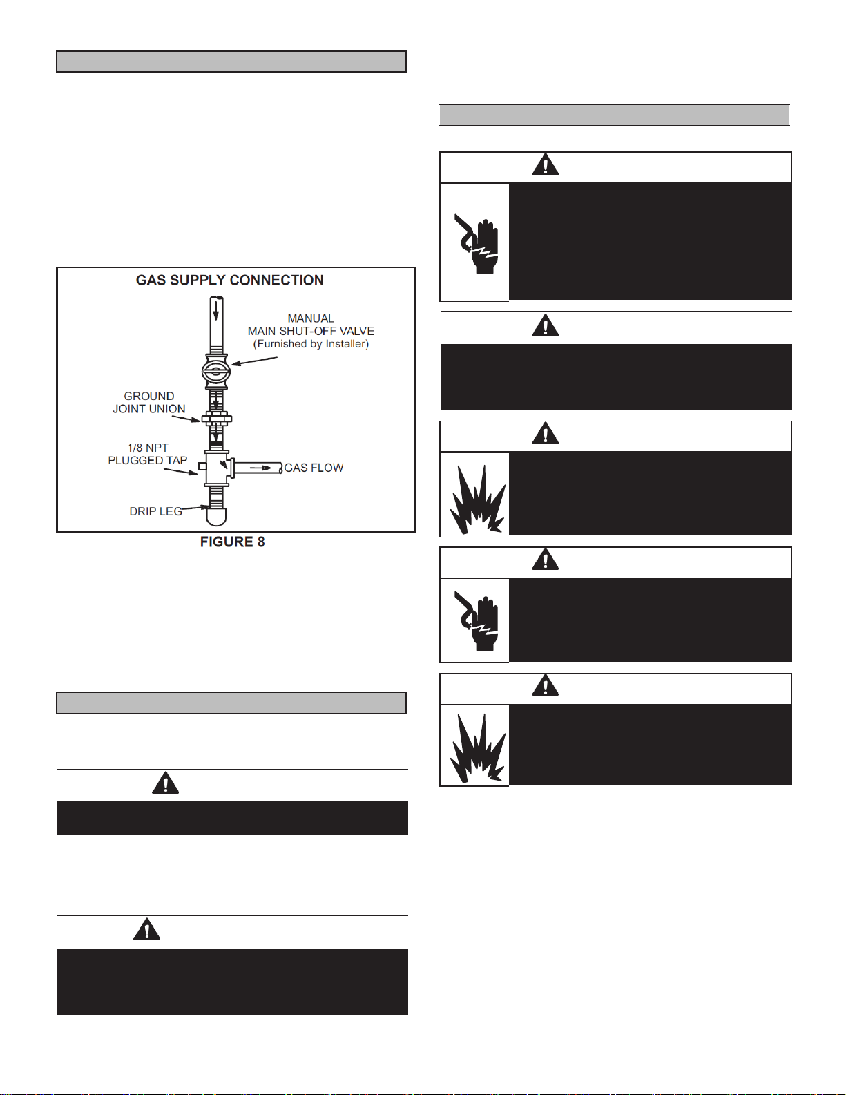
A drip leg should be installed in the vertical pipe run
to the unit. In some localities, codes may require that
a manual main shutoff valve and union (furnished by
installer) be installed external to the unit. Union must be
of the ground joint type. A drip leg should be readily ac-
cessible to permit cleaning and emptying. See figure 8.
NOTE - If a switch box is mounted over electrical knock-
outs on back of unit, leave a minimum of 4” (102mm)
clearance between switch box and drip leg.
A1/8” NPT plugged tap shall be installed immediately up-
stream of the gas supply connection to the heater.
NOTE - Compounds usedon threaded joints of gas pip-
ing must be resistant to the actions of liquefied petroleum
gases.
Aftergas piping is completed, carefully check all piping
connections,(field and factory), for gas leaks. Use asoap
solution or other preferred means.
CAUTION
DO NOT use matches, candles,flame orother sources
of ignition to check for gas leaks.
The appliancemust beisolatedfromthegas supply piping
system byclosingits individual manual gas shutoff valve
during any pressure testing ofthe gas supply system at
testpressuresequaltoorgreaterthan1/2psig(3.45kPa).
NOTE - In case emergency shutdown is required, shut
down main gas valve and disconnect main power to unit.
These devices should be properly labeled by the installer.
Unit Start-Up
FOR YOUR SAFETY READ BEFORE LIGHTING
WARNING
Electric shock hazard. Can cause injury
or death. Do not use this unit if any part
has been under water. Immediately call a
qualified service technician to inspect the
unit and to replace any part of the control
system and any gas control which hasbeen
under water.
WARNING
Install, operate and maintain unit in accordance with
manufacturer’s instructions to avoid exposure to fuel
substances or substances from incomplete combustion
which can cause death or serious illness.
WARNING
Danger of explosion. Can cause injury or
product or property damage. If overheating
occurs orifgas supply fails to shut off, shut
off the manual gas valve to the appliance
before shutting off electrical supply.
WARNING
Electric shock hazard. Can cause injury or
death. Before attempting to perform any
service or maintenance, turn the electrical
power to unit OFF at disconnectswitch(es).
Unit may have multiple power supplies.
WARNING
Danger of explosion. Can cause injury or
productorproperty damage.Youmustfollow
these instructions exactly.
BEFORE LIGHTINGsmell all around the appliance area
for gas. Be sure to smell next to the floor because some
gas is heavier than air and will settle on the floor.
Use only your hand to move the lever. Never use tools. If
thelever willnot move byhand, donottrytorepair it,calla
qualifiedservicetechnician.Forceorattemptedrepairmay
result in a fire orexplosion.
IMPORTANT
The heater and its individual shut off valve must be
disconnected from the gas supply piping system during
any pressuretesting ofthat system at testpressures in
excess of 1/2 psig (3.45kPa). See figure 9.
GasConnection
Leak Check
Page 19
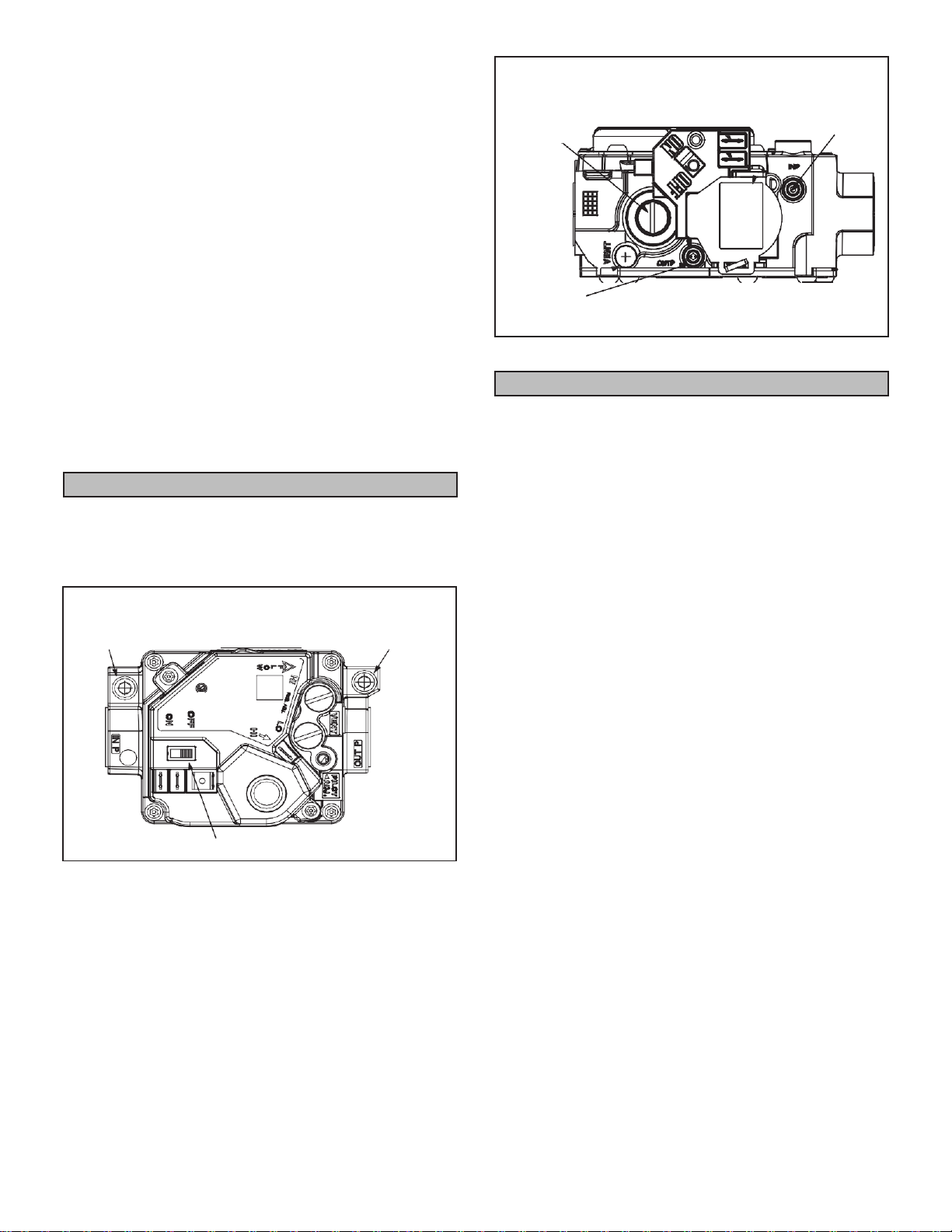
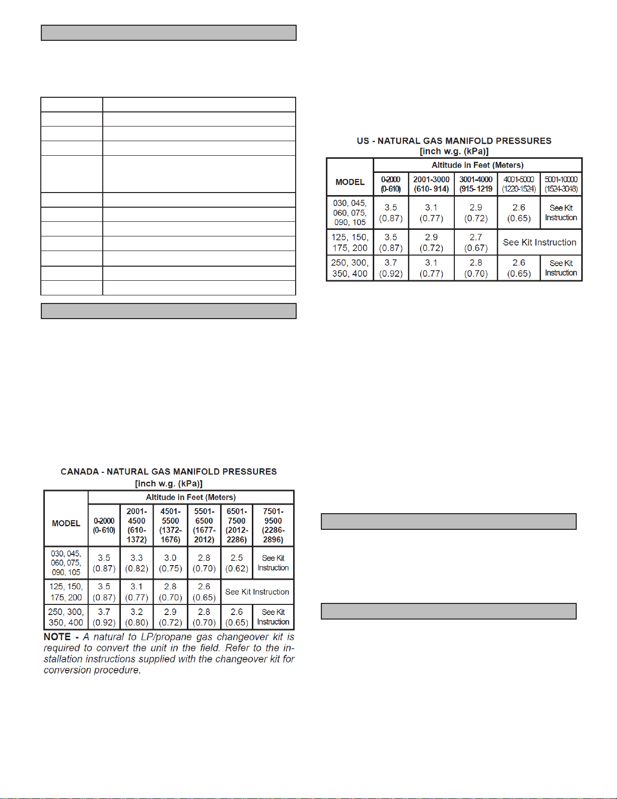
OPERATIONOFWHITERODGERS36HSERIES VALVE
(FIGURE9)AND WHITERODGERS 36G SERIES GAS
VALVE (FIGURE 10)
NOTE - STOP! Read the safety information at the begin-
ning of this section.
1 - Set thermostat to lowest setting.
2 - Turn off all electrical power to appliance.
3 - This appliance is equipped with an ignition device
whichautomatically lightsburners. DONOTattempt
to light the burners manually.
4 - Move lever to OFF.
5 - Wait five minutes to clear out any gas. If you then
smell gas, STOP! Immediatelycall yourgassupplier
from a neighbor’s phone. Follow the gas supplier’s
instructions. Ifyou do not smell gas, go to nextstep.
6 - Move lever to ON.
7 - Turn on all electric power to unit.
8 - Set thermostatto desiredsetting.
9 - If appliancestillwillnotoperate,followtheinstructions
“To Turn Off Gas to Unit” and call your service
technician or gas supplier.
1 - Set thermostat to lowest level.
2 - Turn off all electrical powerto unit if service is to be
performed.
3 - Move lever to OFF
WHITE RODGERS 36H SERIES GAS VALVE
INLET Two-Stage MANIFOLD
PRESSURE PRESSURE
PORT OUTLET
MANIFOLD
PRESSURE
ADJUSTMENT
SCREW
GAS VALVE SWITCH SHOWN IN OFF POSITION
FIGURE 9
WHITE RODGERS 36 GAS VALVE
MANIFOLD Single-Stage INLET
PRESSURE PRESSURE
ADJUSTMENT PORT
SCREW
MANIFOLD
PRESSURE
OUTLET GAS VALVE SWITCHSHOWNIN OFF POSITION.
FIGURE 10
1 - When thethermostat callsforheat, the combustion
air inducer starts immediately.
2 - Combustion air pressure switch proves inducer
operation before allowing ignition sequence to
start. This switch is factory set and no adjustmentis
necessary.
3 - After pre-purge of approximately 30 seconds, the
spark ignition is energized and the solenoid valves
open in the gas valve.
4 - The spark then ignites the gas, the ignition sensor
proves the flame and the combustion process
continues.
5 - In the event that the flame is not detected after the
first 10-second trial for ignition, the controller will
repeat steps 3 and 4 an additional two times before
locking out the gas valve. Ignition control will then
automatically repeat steps 3, 4, and 5 after 60
minutes.
NOTE - Tointerrupt the 60-minute lockout period, move
thermostatfrom“Heat” to“OFF” thenbackto“Heat.” Heat-
ing sequence then restarts at step 1.
6 - The burners must light withoutnoticeable crossover
delay. There must be no flame lifting from theburner
heads, flashback or burning within the burner. The
flames should be predominantly blue in color and
should be approximatelycentered in the tubes with
no apparent impingement taking place.
7 - Theignitioncontrolwillenergizethefanapproximately
30 seconds after ignition is established.
8 - After the thermostat demand is satisfied the gas
valve is closed. Thirtyseconds after the demand is
satisfied, the combustion air inducer is shut off.
9 - The ignition control will shut off the system fan
approximately150secondsafterthegas valve is de-
energize.
To Turn Off Gasto Unit
Heating Sequence of Operation
Page 20
The ignition control contains a green LED which indicates
the following: TABLE5
IGNITION CONTROL LED
LED
UNIT OPERATION
Slow Flash*
Normal Operation - No call for heat
Fast Flash
Normal Operation - Call for heat
2 Flashes
Systemlockout - failed to detect or sustain flame
3 Flashes
Pressure switch failed closed before CAI
is energized or failed open after CAI is
energized
4 Flashes
High limit (S10) or rollout switch open
5 Flashes
Flame sensed and gas valve (GV1) not energized
6 Flashes
On-board microprocessor fault.
7 Flashes
Pressure switch (S18) closed with inducer off.
8 Flashes
Rollout switch(S47/S195) open. Cycle-power to reset.
Steady On
Control board (A3) failure
Steady Off
Internal control board (A3) failture or not power.
In Canada, certification for installation at altitudes
over 4500 feet (1372m) above sea level is the
jurisdiction of local authorities. ADP recommends
derating 4%/1000 feet above 4,500 feet. Refer to
table 6 for natural gas manifold pressures and the
Engineering Handbook for high altitude kit part
numbers.
Units may be fired at full input up to 2000 feet.
(610m) above sea level. Above 2000 feet (610m),
manifold pressure must be adjusted.Adjust pressure
regulator to pressure shown in table 6.
In the US, units may befired at full input up to 2000 feet
(610m) above sea level. Above 2000 feet (610m), unit
must be de-rated by four percent per1000 feet for instal-
lation above 2000 feet.The de-rate may be accomplished
by adjusting the manifold pressure. See table 7. See the
Engineering Handbook forhigh altitude kit part numbers.
TABLE 7
TABLE 6 In some cases, it is necessary to change the pressure switch to
ensure proper operation at higher altitudes. See EHBfor high
altitude pressure switch kits.
The combustion air inducerproving switch is factory set.
No adjustment is necessary.
To check for proper gas flowto the combustion chamber,
determine the Btu inputfrom the appliance rating plate.Di-
vide this input rating by the Btu per cubicfeet of available
gas. Result is the required number of cubic feet per hour.
Determine theflow of gas through the gas meter for two
minutes and multiply by 30 toget the hourly flow ofgas.
1 - Check gas line pressure with unit firing at maximum
rate. A minimum of the following should be
maintained for proper unit operation:
030-105KBTUH - 5” (127mm) w.c. for natural gas
125-400KBTUH - 6” (152mm) w.c. for natural gas
030-105KBTUH - 10.5” (267mm) w.c. for LP/propane gas
125-400KBTUH -11.0” (279mm) w.c. for LP/propane gas
Ignition ControlLED
High Altitude Adjustments
GasFlow
GasPressure Adjustment
This manual suits for next models
16
Table of contents
Other Adp Heater manuals


Popular Heater manuals by other brands


Celcia
Celcia RH03A-P operating instructions

Comfort Glow
Comfort Glow QDE1340 owner's manual

LUCHT LHZ
LUCHT LHZ TECHNOTHERM TTB-E Duo+ Series Manual Installation

Black & Decker
Black & Decker BXRA1500E manual

FAFCO
FAFCO SUPER solar beat Installation and owner's manual

FELLER ENGINEERING
FELLER ENGINEERING OR 23110 manual