Adroit Mitsubishi Electric IQF Series User manual

iQF-Series Modbus RTU Setup 2018/12/18 P a g e | 1
IQF-SERIES MODBUS RTU SETUP

iQF-Series Modbus RTU Setup 2018/12/18 P a g e | 2
- Table Of Contents -
Introduction ___________________________________________________________________________ 3
Equipment Used ________________________________________________________________________ 4
Communication Wiring between CS80 and FX5U ______________________________________________ 5
Wiring and configuration of CS80 connector _______________________________________________________ 5
PU Connector Pinouts __________________________________________________________________________________ 5
Wiring between a Modbus Master and an inverter for RS-485 communication ____________________________________ 6
Wiring between a Modbus Master and multiple inverters for RS-485 communication ______________________________ 6
Wiring and configuration of FX5U _______________________________________________________________ 7
Wiring Procedure _____________________________________________________________________________________ 7
CS80-VSD Setup _______________________________________________________________________ 10
Recommended Parameter Settings _____________________________________________________________ 10
How to change the parameter setting value ______________________________________________________ 11
FX5U-Setup ___________________________________________________________________________ 12
Parameter Setup: ___________________________________________________________________________ 12
Programming _______________________________________________________________________________ 16
Modbus Registers Available to Monitor To/From CS80-VSD __________________________________________________ 16
Function Blocks used to Communicate with the CS80-VSD, or any other Modbus device ___________________________ 19
Monitoring Parameters from the CS80-VSD _______________________________________________________________ 20
Monitoring Values from the CS80-VSD ___________________________________________________________________ 24
Write Bit Commands to the CS80-VSD ____________________________________________________________________ 27
Write Register Commands to the CS80-VSD _______________________________________________________________ 30
Convert and Download Program to the FX5U-PLC __________________________________________________________ 33
iQF-Series Modbus RTU Setup 2018/12/18 P a g e | 3
Introduction
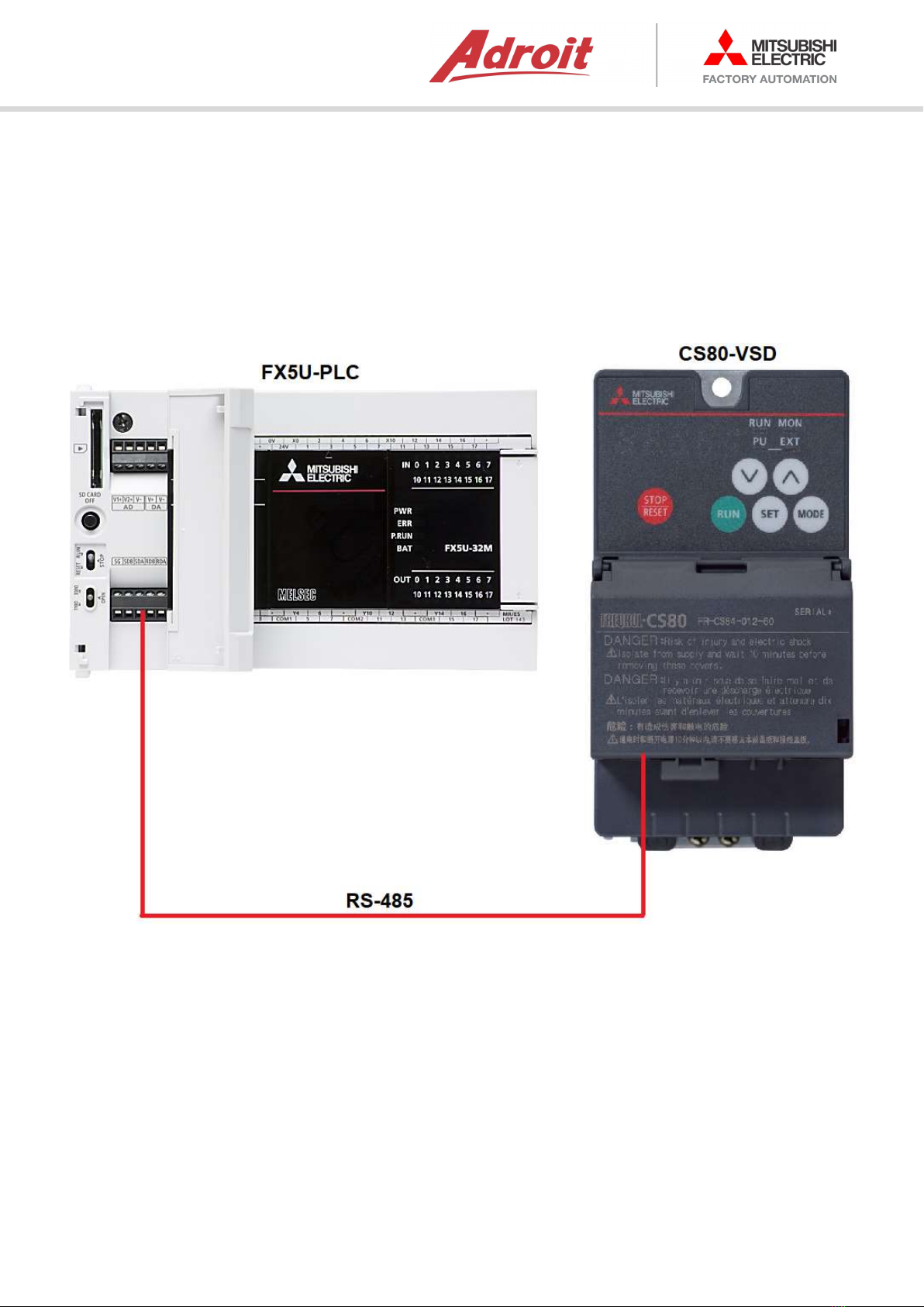
This Manual specifies the functionality and programming of the FX5U-PLC to connect with a CS80-
VSD using Modbus-RTU.
At the end of this manual, you will be able to send and receive messages from the FX5U-PLC to a
CS80-VSD. This manual can also be used as a guideline to connect to other Modbus-RTU devices.
Figure 1

iQF-Series Modbus RTU Setup 2018/12/18 P a g e | 4
Equipment Used
- Freqrol-CS80 VSD
o FR-CS82S-042-60
- GX Works 3
o Version information – 1.050C
- Mitsubishi FX5U-32MR/ES
o Firmware Version – 1.110
o Serial Number – 17X0001 and higher
- Reference Manuals
o FREQROL-CS80 - INSTRUCTION MANUAL (DETAILED) - IB(NA)-0600721ENG-B
o MELSEC iQ-F - FX5 User's Manual (MODBUS Communication) - JY997D56101
o MELSEC iQ-F - FX5 User's Manual (Startup) - JY997D58201
o MELSEC iQ-F - FX5UC User's Manual (Hardware) - JY997D61401
o MELSEC iQ-F - FX5 User's Manual (Serial Communication) - JY997D55901
o MELSEC iQ-F - FX5 User's Manual (MELSEC Communication Protocol) - JY997D60801
o MELSEC iQ-F - FX5 User's Manual (Ethernet Communication) - JY997D56201
iQF-Series Modbus RTU Setup 2018/12/18 P a g e | 5
Communication Wiring between CS80 and FX5U
Wiring and configuration of CS80 connector
Using the PU connector as a Modbus network port enables communication operation from a
Modbus Master, etc.
When the PU connector is connected with a Modbus Master by using a communication cable, a
user program can run and monitor the inverter or read and write to parameters.
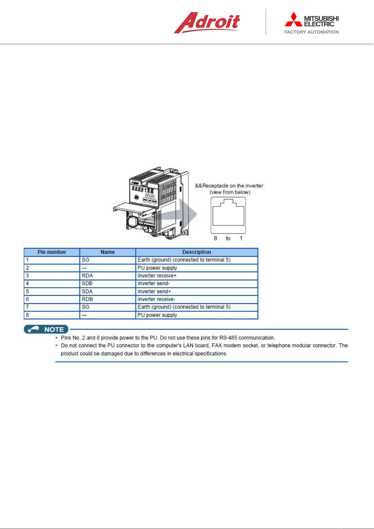
PU Connector Pinouts
Figure 2

iQF-Series Modbus RTU Setup 2018/12/18 P a g e | 6
Wiring between a Modbus Master and an inverter for RS-485 communication
Wiring as below:
Figure 3
Wiring between a Modbus Master and multiple inverters for RS-485 communication
Wiring as below:
Figure 4

iQF-Series Modbus RTU Setup 2018/12/18 P a g e | 7
Wiring and configuration of FX5U
Wiring Procedure
1. Preparing for wiring
a. Prepare cables required for wiring.
b. For RS-485
i. Use shielded twisted pair cables for connecting RS-485 communication
equipment.
ii. Twisted Pair Cable
Figure 5
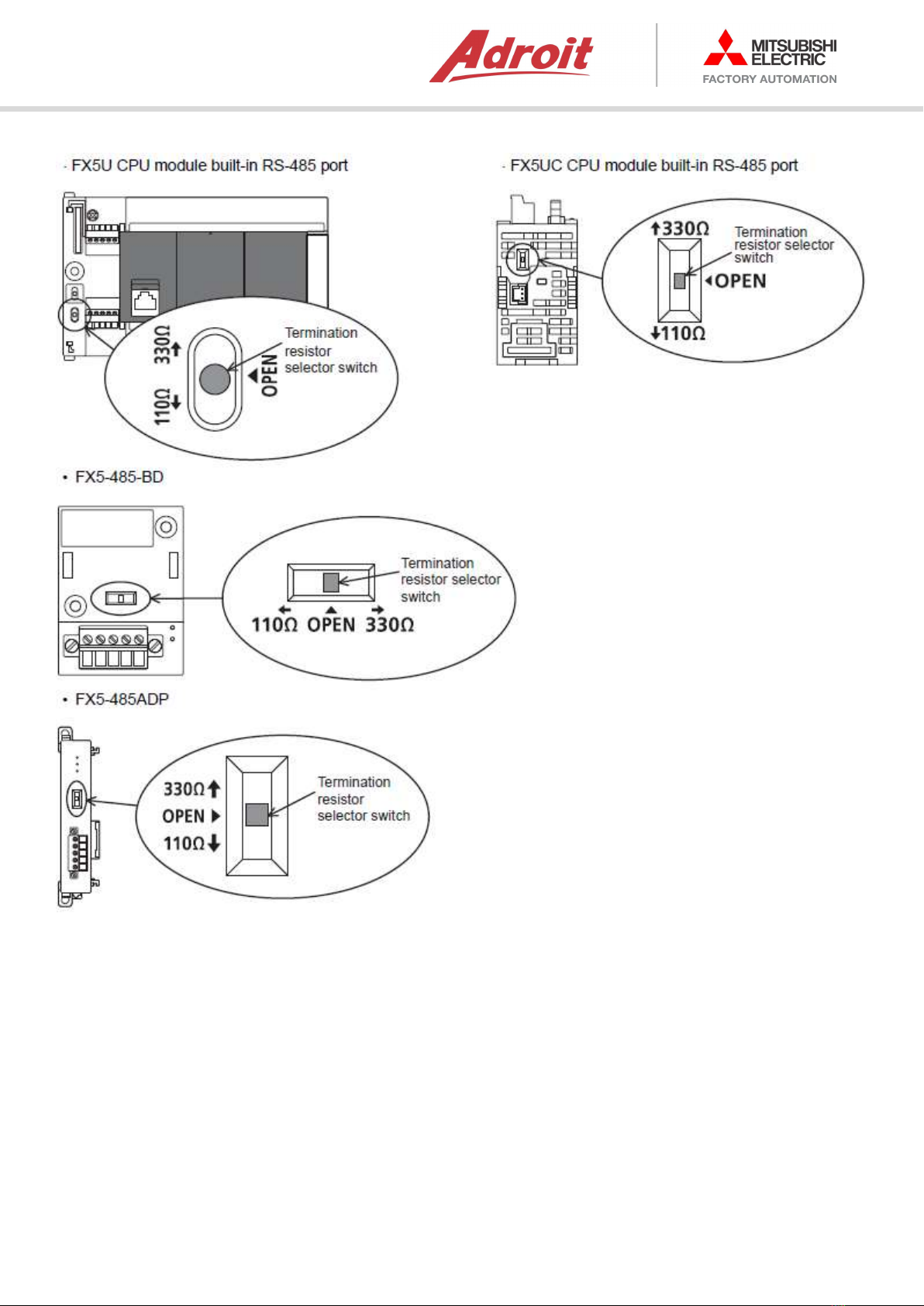
iii. Termination Resistor Setting
1. Make sure to provide a termination resistor at each end of a line.
2. Built-in RS-485 port, FX5-485-BD, and FX5-485ADP have a built-in
termination resistor.
3. Set the termination resistor selector switch accordingly.
Figure 6
iQF-Series Modbus RTU Setup 2018/12/18 P a g e | 8
Figure 7

iQF-Series Modbus RTU Setup 2018/12/18 P a g e | 9
2. Turning off the power to the PLC
a. Before wiring, make sure that the power of the PLC is off.
3. Wiring communication equipment
a. Connect RS-485 communication equipment.
i. Connection Diagram For RS-485 communication
Figure 8

iQF-Series Modbus RTU Setup 2018/12/18 P a g e | 10
CS80-VSD Setup
Recommended Parameter Settings
These are parameters used on the VSD and their settings:
Parameter 0 (Torque) = 10.
Parameter 1 (Max Frequency) = 50.
Parameter 2 (Min Frequency) = 20.
Parameter 3 (Base Frequency) = 50.
Parameter 4 (High Speed Set point) = 50.
Parameter 5 (Middle Speed Set point) = 35.
Parameter 6 (Low Speed Set point) = 20.
Parameter 7 (Acceleration Time) = 5.
Parameter 8 (Deceleration Time) = 5.
Parameter 9 (OL Relay) = 4.20.
Parameter 19 (Motor Name Plate Voltage) = 220.
Parameter 75 (Reset selection/disconnected PU detection/PU stop selection) = 14.
Parameter 77 (Parameter Write Selection) = 2.
Parameter 79 (Operation Mode Set) = 2.
Parameter 117 (PU Communication Station Number) = 1.
Parameter 118 (PU Communication Speed) = 192.
Parameter 119 (PU Communication Stop Bit Length / Data Length) = 0.
Parameter 120 (PU Communication Parity Check) = 2.
Parameter 121 (PU Communication Retry Count) = 1.
Parameter 122 (PU Communication Check Time Interval) = 5.
Parameter 124 (PU Communication CR/LF Selection) = 2.
Parameter 338 (Communication Operation Command Source) = 0.
Parameter 339 (Communication Speed Command Source) = 0.
Parameter 340 (Communication Start-up Mode Selection) = 1.
Parameter 549 (Protocol Selection) = 1.
Parameter 551 (PU mode operation command source selection) = 4.
iQF-Series Modbus RTU Setup 2018/12/18 P a g e | 11
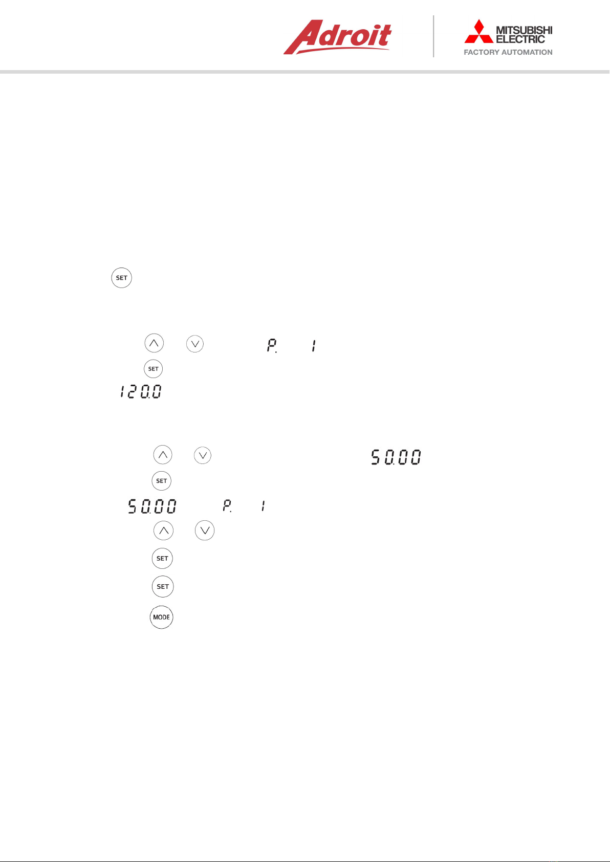
How to change the parameter setting value
How to change the setting of Pr.1 Maximum frequency.
Operating procedure
1.
Turn ON the power of the inverter
The operation panel is in the monitor mode.
2.
Selecting the parameter setting mode
Press to choose the parameter setting mode.
3.
Selecting the parameter
Press or to show " " (Pr.1).
Press to read the present set value.
" " (initial value) appears.
4.
Changing the setting value
Press or to change the set value to " ".
Press to enter the setting.
" " and " " are displayed alternately.
Press or to read another parameter.
Press to show the setting again.
Press twice to show the next parameter.
Hold for one second to return the display to the first screen in the monitor
mode (the monitor item initially set in the first screen is the frequency).
5.
Turn the Power of the VSD from ON to OFF, then back to ON again in order for the VSD to
accept the new settings.
NOTE

iQF-Series Modbus RTU Setup 2018/12/18 P a g e | 12
FX5U-Setup
For the MODBUS serial communication setting of the FX5, set parameters with GX Works3.
Setting of parameter differs according to the module used. The procedure for each module is as
follows.
Parameter Setup:
Step 1: Open GX Works 3 and start a new project:
Figure 9
Step 2: Select:
Series – FXCPU
Type – FX5U
Program Language – FBD/LD
Figure 10

iQF-Series Modbus RTU Setup 2018/12/18 P a g e | 13
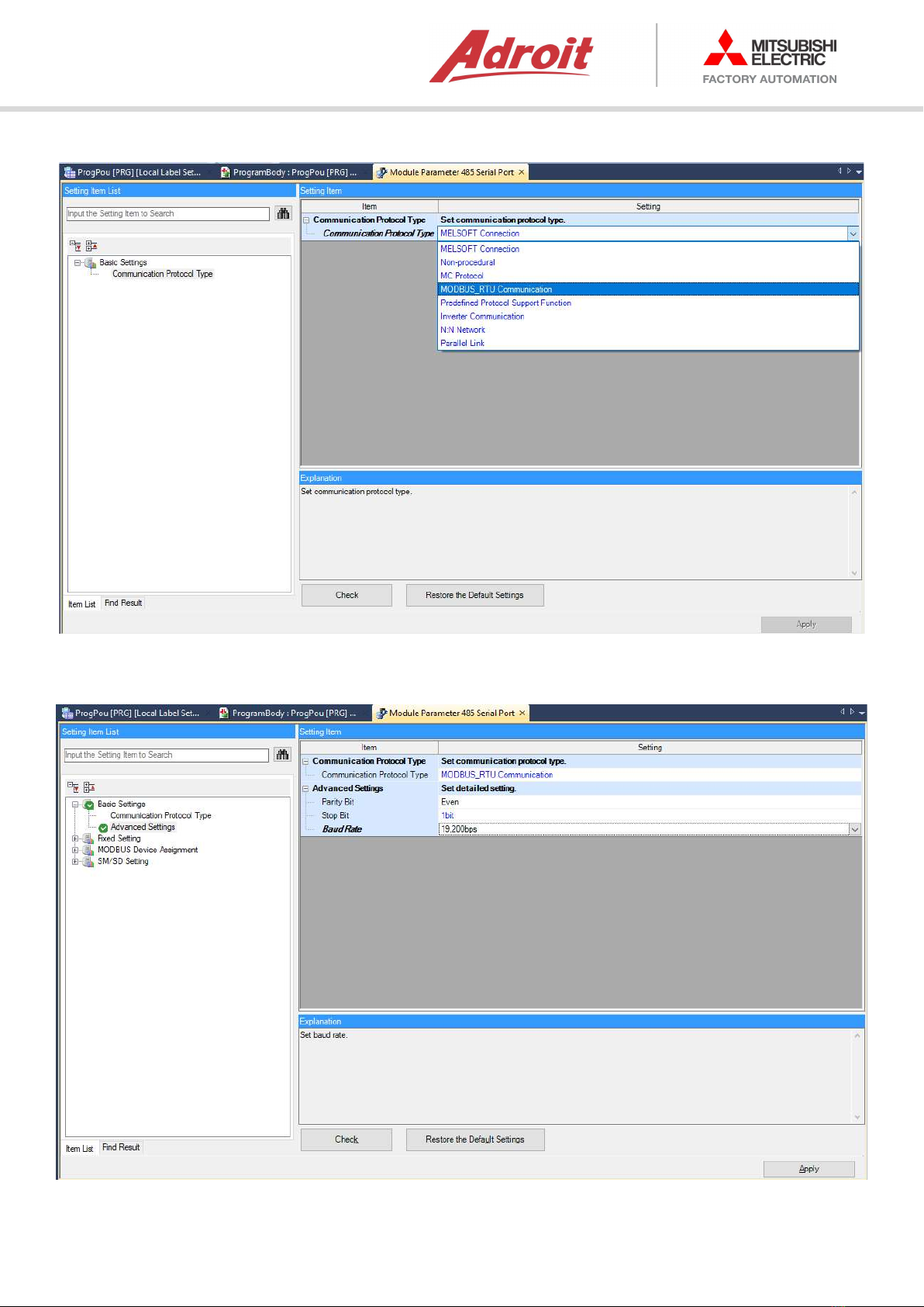
Step 3: "Navigation window" -> [Parameter] -> [FX5UCPU] -> [Module Parameter] -> [485 Serial
Port]:
Figure 11
iQF-Series Modbus RTU Setup 2018/12/18 P a g e | 14
Step 4: Select MODBUS_RTU Communication:
Figure 12
Step 5: Adjust Parity Bit = Even, Stop Bit = 1bit and Baudrate = 19,200bps:
Figure 13

iQF-Series Modbus RTU Setup 2018/12/18 P a g e | 15
Step 6: Click “Check” button, wait for message box - “no error found”:
Figure 14
Step 7: Click “Apply” button:
Figure 15

iQF-Series Modbus RTU Setup 2018/12/18 P a g e | 16
Programming
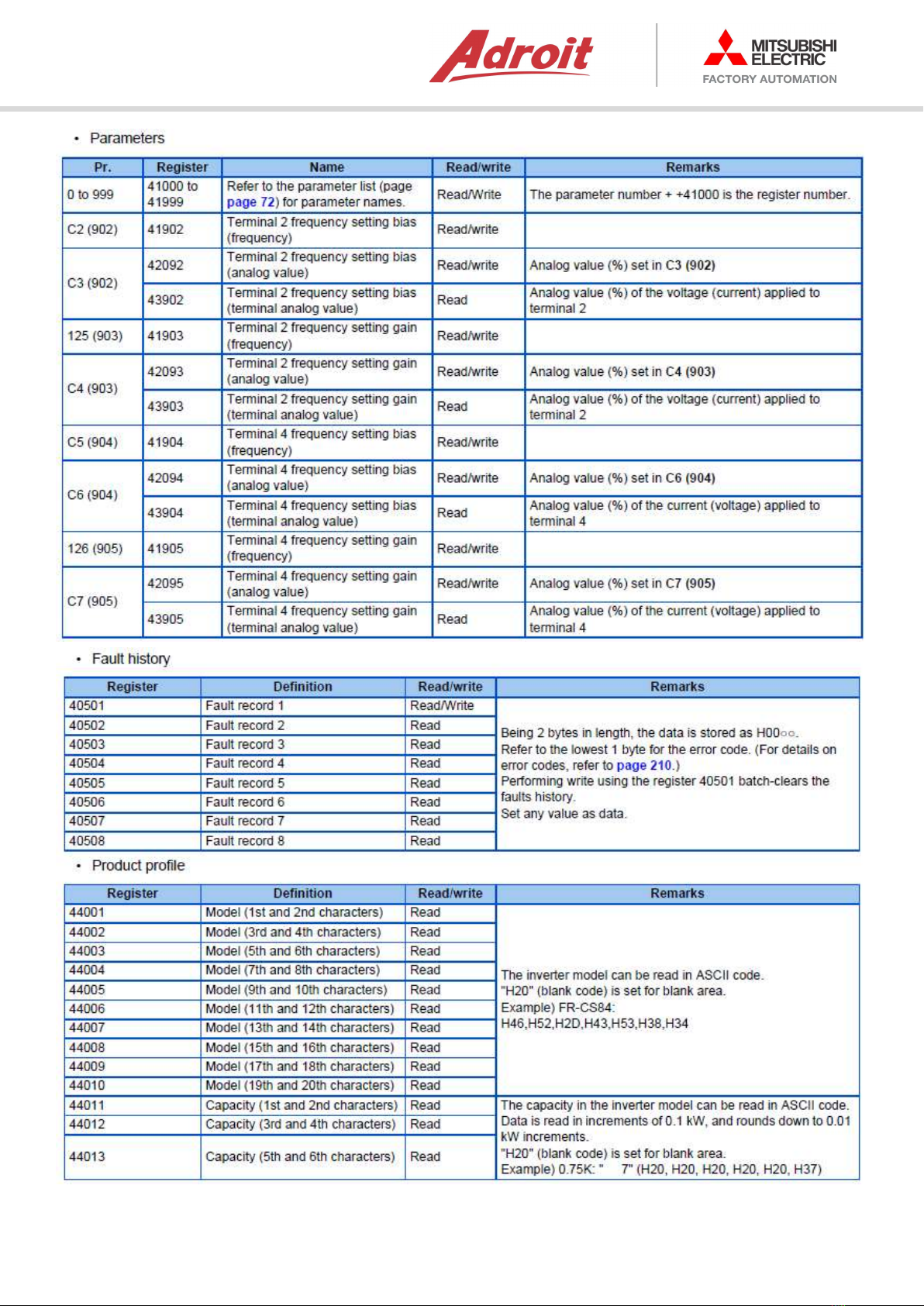
Modbus Registers Available to Monitor To/From CS80-VSD
Figure 16
iQF-Series Modbus RTU Setup 2018/12/18 P a g e | 17
Figure 17

iQF-Series Modbus RTU Setup 2018/12/18 P a g e | 18
Figure 18
iQF-Series Modbus RTU Setup 2018/12/18 P a g e | 19
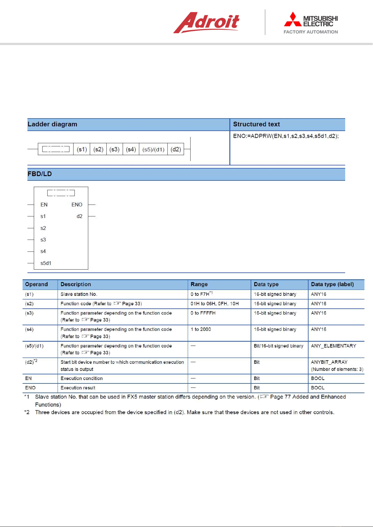
Function Blocks used to Communicate with the CS80-VSD, or any other Modbus device
In the FX5 master function, communication is executed with the slave station using the ADPRW
instruction. This instruction allows to communicate (read/write data) with the slave station by the
function code which is supported by the master.
Figure 19

iQF-Series Modbus RTU Setup 2018/12/18 P a g e | 20
Monitoring Parameters from the CS80-VSD
Step 1: Create a Structured Data-Type for VSD Parameters
"Navigation window" -> [Structured Data Types] -> [
Right Click
] -> [Add New Data]:
Figure 20
Step 2: Edit the Structured Data Type by adding the Parameters to be monitored:
Figure 21
Table of contents
Other Adroit Remote Control manuals

Popular Remote Control manuals by other brands

Kirkland Signature
Kirkland Signature Remote Control 2 Getting started

Niles
Niles SVC100R Specifications

Allo RemoteControl
Allo RemoteControl WHY EVO instructions

Magnavox
Magnavox MRU2600 - Universal Remote Control Specifications

GM-Racing
GM-Racing XG-6i Race Spec instruction manual

Gyration
Gyration GYR4101US owner's manual


