Adrona Q-Front N Trace User manual

Water purification system
Adrona Q-Front N
INSTALLATION & OPERATION MANUAL
Version 1.0 (2019)
No. LVRIG38118A

INTRODUCTION
2
Table of Contents
INTRODUCTION ........................................................................................................................................ 3
Using This Manual ................................................................................................................................ 3
Safety Information ............................................................................................................................... 3
Contact Adrona .................................................................................................................................... 3
PRODUCT OVERVIEW ............................................................................................................................... 4
Adrona Q-Front N Water System General Description ........................................................................ 4
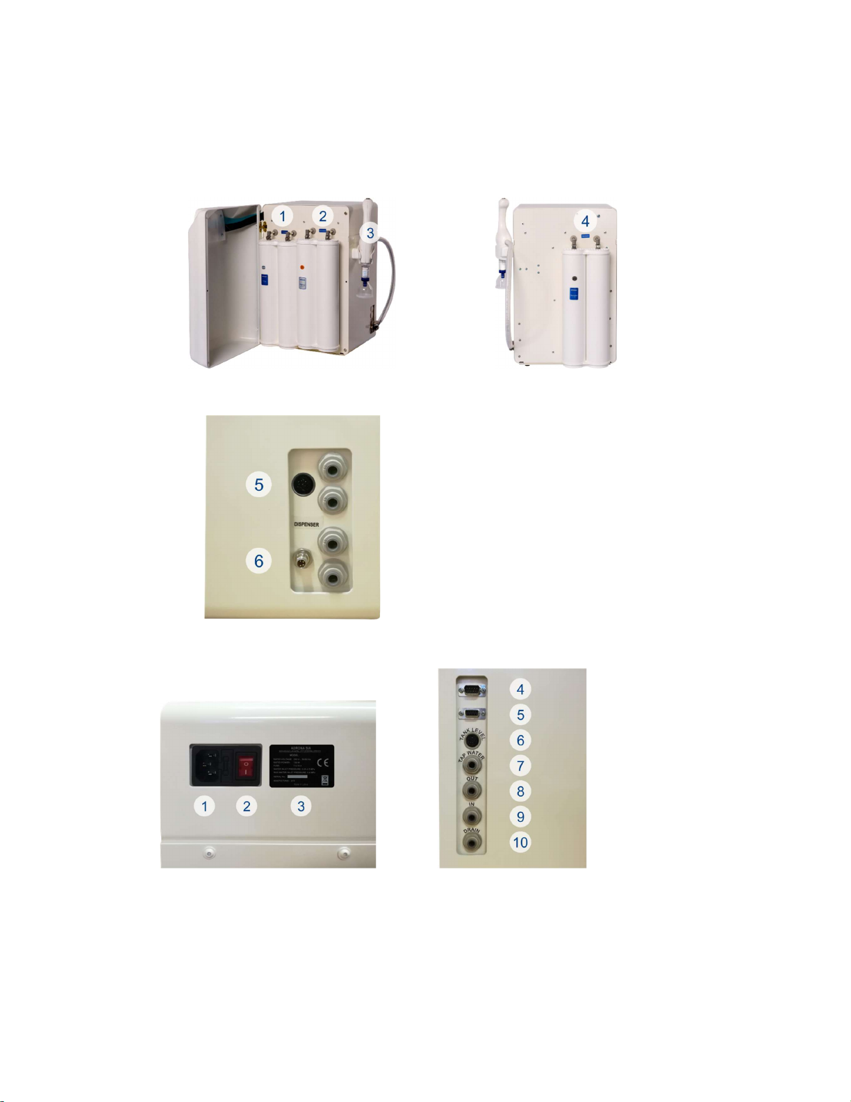
System Overview ................................................................................................................................. 4
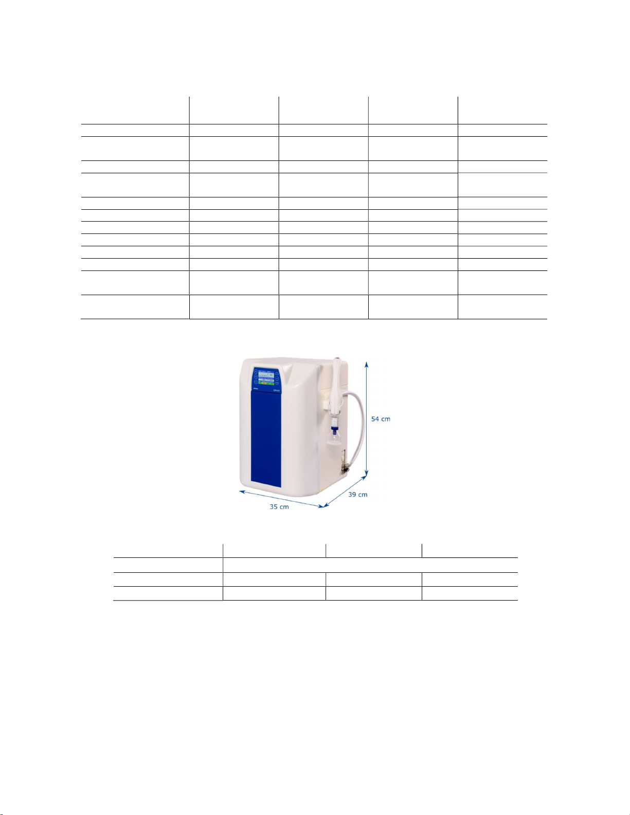
Water Specifications ............................................................................................................................ 5
Technical Specifications ....................................................................................................................... 5
System Components in Flow Chart ...................................................................................................... 6
Principle ............................................................................................................................................... 6
PRE-INSTALLATION ................................................................................................................................... 7
Feedwater requirements ..................................................................................................................... 7
Feedwater connection ......................................................................................................................... 7
Site requirements ................................................................................................................................ 8
Environmental requirements ............................................................................................................... 8
Water leakage safety ........................................................................................................................... 8
UNPACKING .............................................................................................................................................. 9
INSTALLATION .......................................................................................................................................... 9
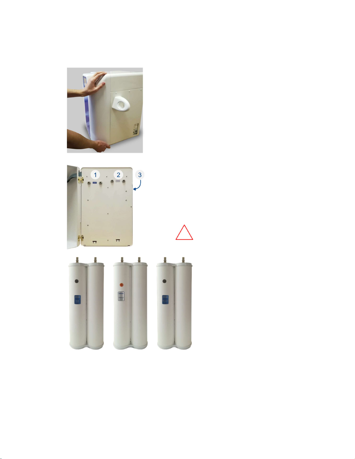
Preparation of the System ................................................................................................................... 9
Introduction to John Guest tubing system .......................................................................................... 9
Front and side panel .......................................................................................................................... 10
Pro tank .............................................................................................................................................. 11
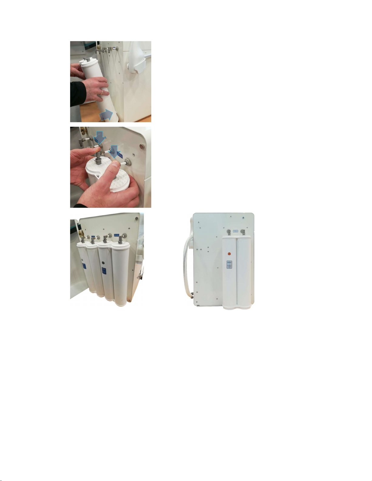
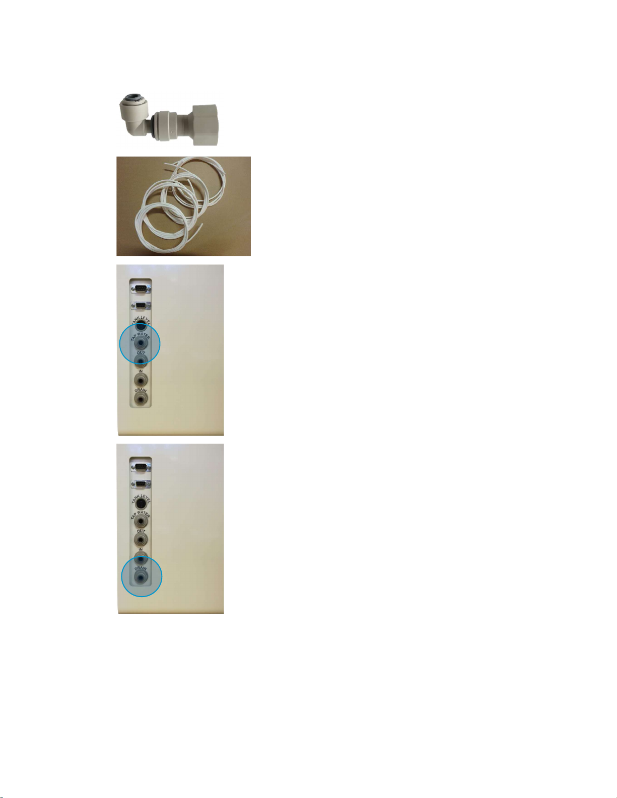
Installation procedure ....................................................................................................................... 12
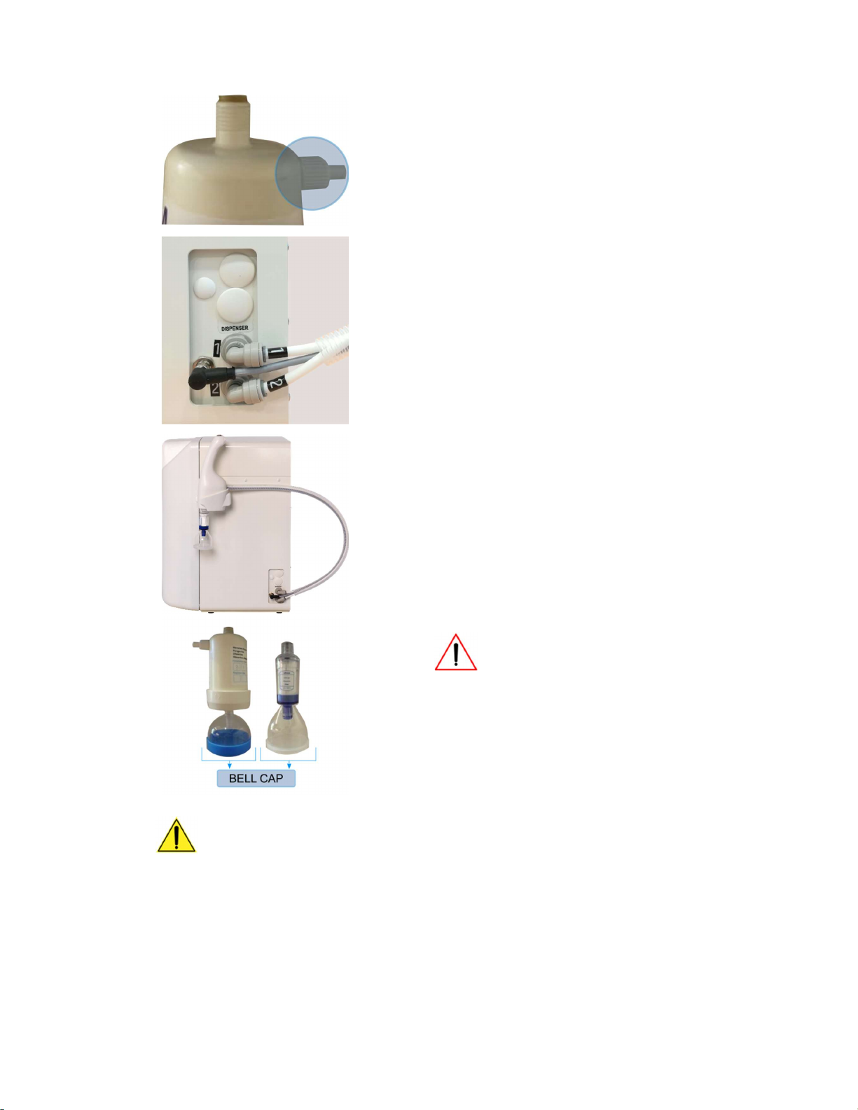
Side mounted dispenser installation ................................................................................................. 14
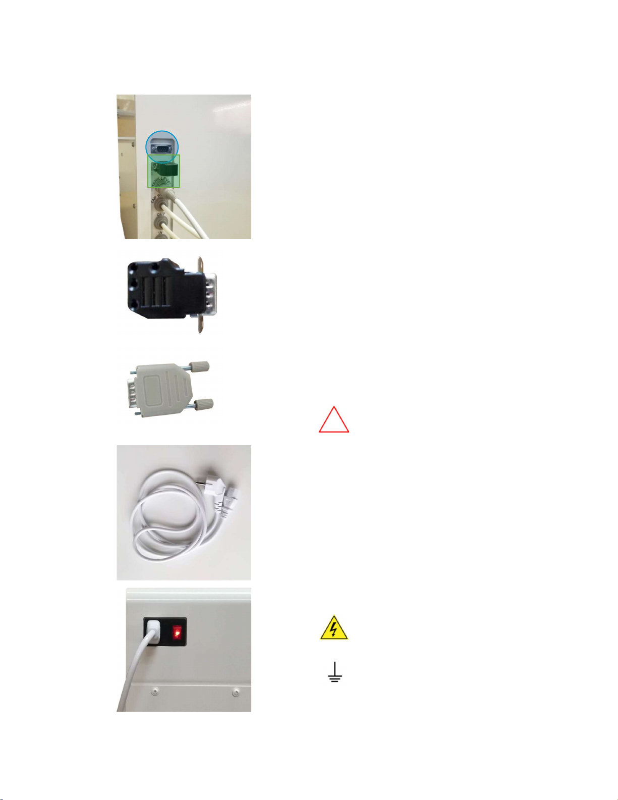
Connection to tank cable ................................................................................................................... 18
Connection to PC, validation port and power plug ............................................................................ 19
Calibration ......................................................................................................................................... 20
USING THE SYSTEM ................................................................................................................................ 20
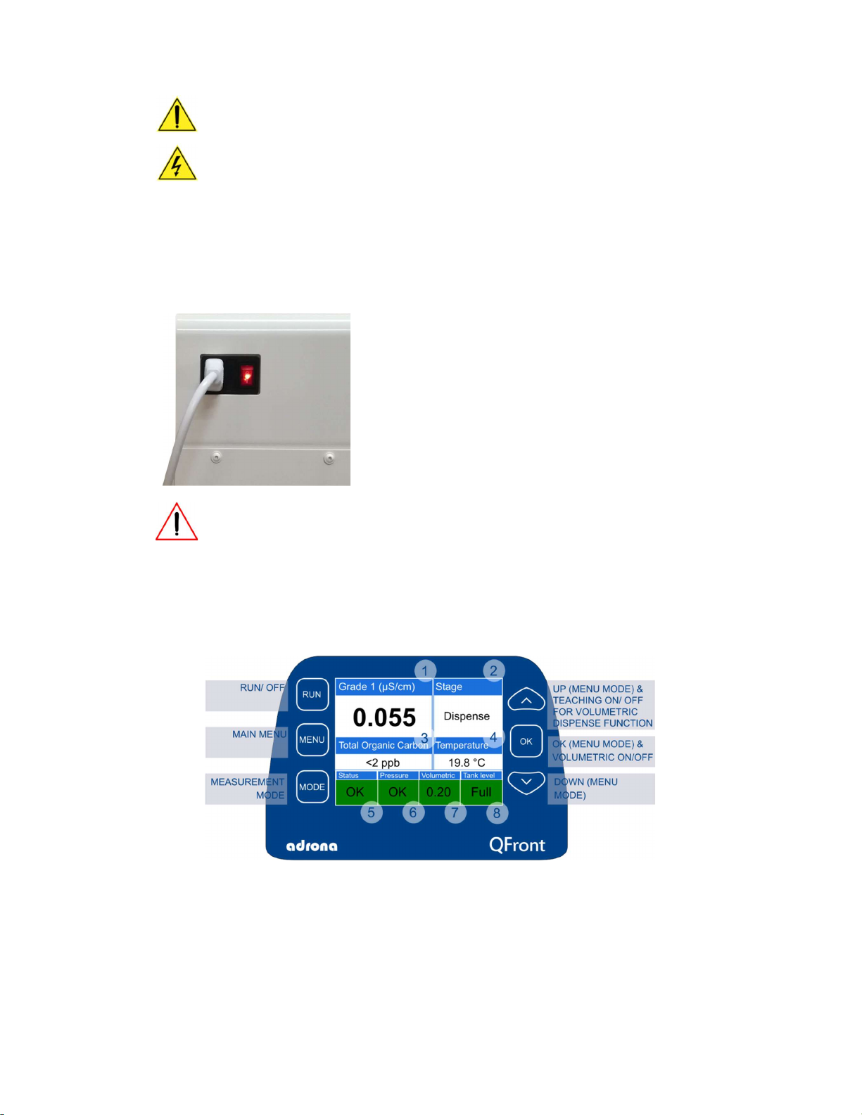
Display ............................................................................................................................................... 20
Sensor validation ............................................................................................................................... 21
TOC reduction and monitoring .......................................................................................................... 22
TOC monitoring module (optional) operation principle .................................................................... 22
Diagnostic screen ............................................................................................................................... 22
Connection to PC ............................................................................................................................... 23
Rinsing the system ............................................................................................................................. 23
Introduction to Q-Front N operating modes ..................................................................................... 24
Operating Q-Front N tap water systems ............................................................................................ 32
MAINTENANCE ....................................................................................................................................... 35
Maintenance schedule....................................................................................................................... 35
Replacement of pre-filter module ..................................................................................................... 36
Replacement of polishing module ..................................................................................................... 38
Calibration ......................................................................................................................................... 39
Empty the tank .................................................................................................................................. 40
Adrona Recirculation Sanitization...................................................................................................... 40
TROUBLESHOOTING ............................................................................................................................... 41
SPARE PARTS AND CONSUMABLES ........................................................................................................ 42
WARRANTY AND CLAIMS ........................................................................................................................ 42

INTRODUCTION
3
INTRODUCTION
Using This Manual
This is a user manual for Adrona Q-Front N water purification systems. We strongly advise you to read
this manual before installing and using the water purification system.
Safety Information
WARNING! Read and understand all sections in this guide before installing or operating the system.
The symbols used below are internationally accepted symbols that warn of potential hazards with
electrical products.
This HAZARD symbol is used to refer to instructions in this manual that need to
be done safely and carefully.
This ATTENTION symbol is used to refer to instructions in this manual that need
to be done carefully.
This ELECTRICAL GROUND symbol is used to refer to a position where an
electrical ground connection is made.
This ELECTRICAL DANGER symbol means that there are dangerous voltages
present within the unit.
This DANGER symbol indicates that it is necessary for the user to refer to the
owner’s manual, read, understand and follow the instructions.
This UV RADIATION symbol indicates the ultraviolet radiation (UV) danger.
Failure to comply with safety instructions may result in personal injury.
Ensure that anyone who operates the water purification system has received instructions in both
general safety practices for laboratories and specific safety practices for the unit.
Contact Adrona
Adrona SIA
Kalnciema st. 209
Riga, LV-1046
LATVIA
Phone: +371 67551894
Mob: +371 26112517
info@adrona.lv
www.adrona.lv

PRODUCT OVERVIEW
4
PRODUCT OVERVIEW
Adrona Q-Front N Water System General Description
Adrona Q-Front N is Ultrapure water purification systems which requires external water tank that use
tap water as feed water (tap water system).
There are 4 sub-variations available for each system: Trace, HPLC, Bio and Bio UF.
Water purification system Adrona Q-Front N produces pure water that complies with ISO 3696 Grade II
and Grade I water requirements.
Pure (ISO 3696 Grade II) water applications include, but are not limited to:
Feed for laboratory equipment (washing machines, clinical analyzers,
humidifiers, autoclaves, hydrogen gas generators);
Manufacturing of chemical and biochemical reagents;
Buffer preparation;
Microbiological media preparation;
In some cases - sensitive analytical techniques (e. g. atomic absorption, ICP-OES);
Wet chemistry;
Spectrophotometry.
Ultrapure (ISO 3696 Grade I) water applications include but are not limited to:
High sensitivity analytical techniques (ICP-MS);
High performance liquid chromatography;
TOC analysis
Molecular biology;
Cell culture.
System Overview

PRODUCT OVERVIEW
5
Water Specifications
Purified water
specification Q-Front N Trace Q-Front N HPLC Q-Front N Bio Q-Front N Bio UF
Grade I water resistivity
18.2 MΩ x cm
18.2 MΩ x cm
18.2 MΩ x cm
18.2 MΩ x cm
Grade I water
conductivity
0.055 μS/ cm 0.055 μS/ cm 0.055 μS/ cm 0.055 μS/ cm
Grade
I
I
water resistivity
>10
MΩ x cm
>10
MΩ x cm
>10
MΩ x cm
>10
MΩ x cm
Grade II water
conductivity
<0.1 μS/cm <0.1 μS/cm <0.1 μS/cm <0.1 μS/cm
TOC <10 ppb <2 ppb <2 ppb <2 ppb
RNase
-
-
<0.01 ng/mL
-
DNase - - <4 pg/μL -
Bacteria <0.01 CFU/mL <0.01 CFU/mL <0.01 CFU/mL <0.01 CFU/mL
Endotoxins <0.15 EU/mL <0.15 EU/mL < 0.001 EU/mL -
Particles >0.22 μm <1/ per mL <1/ per mL - -
Nominal flow, pure
water (to storage tank)
10 L/h
10 L/h
10 L/h
10 L/h
Dispense rate, ultrapure
water Up to 2 L/min Up to 2 L/min Up to 2 L/min Up to 2 L/min
Technical Specifications
Dimensions and weight
Trace
HPLC
Bio /
Bio
UF
Dimensions (W*D*H) 35*39*54 cm
System weight
27
kg
28
kg
29
kg
Operating weight 30 kg 31 kg 32 kg
Noise level
Water purification system Q-Front N can generate a maximum sound pressure level of 47 dB at 1 m
distance from the system.
Electrical requirements
The water purification system is configured for 230 V ± 5%, 3.15 A max.
In areas where the supplied power is subject to voltage fluctuations exceeding 10% of the nominal
volume, a power line regulator may be required.
Power supply receptacle should be within 1.5 meters from the installation site.

PRODUCT OVERVIEW
6
System Components in Flow Chart
Principle
The hydraulic diagram (flowchart) of the Adrona Q-Front N water purification system is shown in
Q-Front N Trace and Q-Front N HPLC/ Bio/ Bio UF flow charts above.
The input valve controls intake of feed water from the tap. The first purification stage consists of the
pre-filter cartridge (part no. 10411) including activated carbon intended to remove particles, free
chlorine, organics and colloids. A pressure switch controls feed water pressure.
The boost pump is used to maintain pressure at the level necessary for the efficient operation of the
reverse osmosis membrane, deionization module (part no. 10311), and UV sterilization module (Bio
configuration only). The feed flow goes to the membrane where it splits into two parts: the permeate,
diffused through the membrane, and the concentrate which passes over the membrane, carrying away
contaminants to drain. The permeate goes to the third purification step – deionization module (part
no. 10311) where the remaining dissolved contaminants are removed.
Before entering the tank, water is sterilized by an UV lamp (Bio configuration only, also available as an
option). Water quality is controlled by Grade II water conductivity sensor. LCD display provides
information about the system status.
Purified water is stored in the tank. Water in the tank meets the requirements of ISO 3696 Grade II.
In order to obtain Grade I water, there is a recirculation loop connected to the tank.
For Trace modification this loop includes recirculation pump, polishing module (part no.
10031), Grade I sensor as well as dispense port with microfilter (part no. 10012).
HPLC, Bio and Bio UF configuration additionally includes photooxidation module (part no.
10018) and TOC monitor.
Q-Front N Bio system has an ultrafilter (part no. 10120) instead of microfilter.
Q-Front N Bio UF system has an in-line ultrafilter (part no. 11200) before microfilter.

PRE-INSTALLATION
7
PRE-INSTALLATION
Make sure the pre-installation requirements are met before installing the system.
Feedwater requirements
Feedwater properties:
Type of feedwater Potable
Minimum pressure ≥ 0.4 bar
Maximum
pressure
≤
6
bars
Conductivity <1500 µS/cm
Temperature 5 to 35°C
pH
4
-
10
Fouling Index <5
Iron <0.1 ppm as CaCO3
Aluminum
<0.05 ppm as CaCO
3
Manganese <0.05 ppm as CaCO3
Free Chlorine <1 ppm
Langelier Saturation Index <+0.2
TOC <2000 ppb
Feedwater connection
Feedwater Piping
Connection
1
/
2
”
Male NPTF
Feedwater should be filtered with 1 μm sediment filter. If the filter is not installed, the input strainer
may become clogged thus blocking the water flow.
Check if sediment filter is installed in tap water
supply line. There should be at least one sediment
filter (pore size 1 μm). The sediment filter is
usually available from a local plumbing store. If
you cannot obtain a sediment filter locally, you
can order tap water line pre-filter set from
Adrona. The part number is 10170 (carbonpp/ PP
1 μm) or 10171 (polyphosphate/carbonpp/1 μm).
Feedwater connection
Feed water hardness does affect produced water quality. Operation of the system with hard feed water
may result in pre-mature clogging of reverse osmosis membranes and reduced Grade II or Grade I water
flow.
Therefore, it is strongly recommended to install a water softener or polyphosphate filter if
water hardness is above 160 ppm.
Feed water connection port has to be 1/2” NPTF (male) thread. The system is equipped with feed water
tube (1/4’’ OD) and adapter for 1/2” NPTF (female) water supply connection. The feed water tube
should be connected to the 1/4” John Guest port of the adapter. Feed water connection port should be
equipped with a valve allowing shutting off water supply.

PRE-INSTALLATION
8
Drain pipe should be lower that the level of the instrument and the level of the OVERFLOW
port of the tank. The water purification system has 1/4” OD drain pipe. The OVERFLOW port
of the tank is intended for 3/8” OD pipe with stem elbow 3/8”.
Feed water supply connector and drain should be within 3 meters from the installation site.
Please note that in case of Q-Front N system pre-filter Q (part no. 10411) module pre-
mature clogging, we will ship the new pre-filters under warranty only if we get a photo of
the sediment filter installed in the tap water line.
Site requirements
The system requires up to 350*390*540 mm (W*D*H) space on the bench. The system is equipped
with water storage tank “Pro” that requires up to 390*440*600 mm (W*D*H) space. The tank can be
placed under the bench. The system can also be mounted on a wall to save space on the laboratory
bench.
Environmental requirements
The water purification system is intended for indoor use only, in an environment that has
nonconductive pollutants only.
Ensure that the site is maintained under the following conditions:
Condition Acceptable range
Temperature
15 to 30 °C (59 to 86 °F)
Humidity 20% to 80% relative humidity, noncondensing
Water leakage safety
- Make sure that all water connection tubes are kink-free.
- Make sure that all water connections are tight.
- Feed water supply connector and drain should be within 3 meters or less from the installation
site.
- Feedwater connection port has to be 1/2” NPTF male thread.
When installing the tank, connect the fitting marked OVERFLOW to the drain. Make sure that
the drain level is lower than the OVERFLOW fitting level. This will prevent water leakage in
case of tank level sensor failure.
A 1 m sediment filter has to be installed in the feedwater supply line. Failure to install the
filter may result in clogging of the strainer inside the system and water flow blockage.

UNPACKING
9
UNPACKING
Remove packing materials carefully and retain for them future shipment or storage of the unit. Examine
the unit carefully for any damage incurred during transit. The warranty does not cover in-transit
damage.
Due to the unit’s weight its unpacking and installing is to be carried out by two persons.
When opening the shipping box, we advise to compare received parts with the Packing List
included.
Contact Adrona if any part is missing.
INSTALLATION
Preparation of the System
Review “Pre-installation requirements” chapter above.
Unpack the water purification system and place it on the laboratory bench.
Remove the protective packing materials.
Introduction to John Guest tubing system
Adrona water purification systems are equipped with John Guest push-fit fittings and tubes. We will
use abbreviation JG for John Guest parts in further text.
To make a connection, the tube is simply pushed in
by hand; the unique patented John Guest collet
locking system then holds the tube firmly in place
without deforming it or restricting flow
Push the tube into the fitting, to the tube stop
Pull on the tube to check it is secure. Test the
system before use
To disconnect, ensure the system is depressurized,
push the collet square against the fitting. With the
collet held in this position the tube can be removed

INSTALLATION
10
Front and side panel
Look at the front and side panels of the Adrona Q-Front N water purification system and locate pre-
filter and deionization module installation sites as well as inlet and outlet fittings.
Front panel
Rear panel
1 – pre-filter Q module (part no. 10411)
2 – polishing Q module (part no. 10031)
3 – flexible dispenser in holder
4 – deionization Q module (part no. 10311)
Side panel – right lower part
5 – connection to the dispenser
“Flow Point 3” (available as additional
equipment)
6 – connection to the flexible dispenser
Side panel – left upper part Side panel – left lower part
1 – electric cable plug
2 – power switch
3 – Information about system & serial
number (depending on configuration
sticker could be placed on the rear panel)
4 – connection to PC
5 – operation/ validation port
6 – TANK LEVEL connection
7 – TAP WATER 1/4” connection
8 – OUT (connection to the tank)
9 – IN (connection to the tank)
10 – DRAIN 1/4” connection

INSTALLATION
11
Pro tank
Adrona Q-Front N systems are equipped with the “Pro” 30 l tank with level sensor, base and tap
(part no. 11015). It is an optimal solution for Grade II water storage.
There are available other tanks with different volume. See price list for further information.
Front view Rear view
Top close view Rear close view
1 – “TANK LEVEL” connector
2 – “OVERFLOW” tube
3 – A cap
4 – Air filter
5 – Water tap
6 – “REC IN” (connection to the system)
7 – “REC OUT” (connection to the system)

INSTALLATION
12
Installation procedure
Open the front door where pre-filter set and polishing module are located.
[1]
Carefully open the front door holding the upper
and lower part with both hands
[2]
Locate the installation slots.
We advise you to do installation in following order:
1 – pre-filter Q module (part no. 10411)
2 – polishing Q module (part no. 10031)
3 – deionization Q module (part no. 10311) is
located on the rear panel
Installation process of pre-filter module,
polishing and deionization module is
identical
[3] [4] [5]
Locate the modules:
1 – pre-filter module is marked with
BLUE sticker;
2 – polishing module is marked
with SILVER sticker
3 – deionization module is marked
with BLUE sticker;

INSTALLATION
13
[6]
Place the module in the slit
[7]
Place connector tubes in slots.
Make sure that connectors are properly attached
[8]
[9]
When the modules and prefilters are installed, it should to look like in pictures no. 8 and no. 9.
Make sure if all the connectors are properly attached and close the front panel
.

INSTALLATION
14
Side mounted dispenser installation
[1]
Side mounted dispenser consists of:
- dispenser arm with flexible tube;
- ultrafilter or microfilter (depending on
configuration);
- O-ring
[2]
0.22 m dispense filter packaging
(part no. 10012)
For HPLC, Trace and Bio UF
configuration only
[3]
Ultrafilter packaging (part no. 10120)
For Bio configuration only
[4] [5]
O-rings:
1 – black for 0.22 m dispense filter
2 – yellow for ultrafilter
[6]
- Unpack the dispense filter and screw it to
the dispenser.
- Before that, make sure that the O-ring is
inside the holder

INSTALLATION
15
[7]
For Bio configuration:
1 – unpack the ultrafilter and screw it to the
dispenser.
2 – before that, make sure that the yellow O-
ring is inside the holder;
3 – loosen the degassing valve a little bit to get
rid of air
[8]
Connect the flexible tube’s connectors to the
system
[
9
]
Use the side mounted holder to place dispenser
while it is not in use
[10]
After water dispensing always put
the bell cap back to the bell
The microfilter (or ultrafilter) should be rinsed prior to use!
When the tank is full, press the “Dispense” button and rinse the microfilter (or ultrafilter)
with at least 10 liters (or 20 liters respectively) of purified water.

INSTALLATION
16
Connection of tubing
[1]
Locate the 1/2” NPT thread adapter
[2]
There are overall four 1/4” JG tubes in the set.
You should connect one 1/4” JG tube to the
1/2” NPT thread adapter
[3]
Connect the feed water to the
1/4” JG connection marked TAP WATER
[4]
Connect 1/4” JG connection marked DRAIN to
the local drain using 1/4” JG plastic tube

INSTALLATION
17
[5]
[6]
The next step is tank connection to the system:
1 – locate IN and OUT connections on the Q-
Front lower left side of the side panel [pic.
5];
2 – locate REC IN and REC OUT connections
on the tank’s rear panel [pic. 6];
3 – use two 1/4” JG plastic tubes for
connection [pic. 2];
4 – connect IN on Q-Front system [pic. 5] with
REC OUT on the tank [pic. 6] (marked with
GREEN square);
5 – connect OUT on Q-Front system [pic. 5]
with REC IN on the tank [pic. 6] (marked
with BLUE circle)
[7]
Locate 3/8” JG tube with JG elbow adapter
[8]
Connect OVERFLOW port of the tank to the drain
using the 3/8” JG tube with JG elbow adapter
(3/8”)
When installing the tank, connect the
fitting marked “OVERFLOW” to the
drain. Make sure that the drain level is
lower than the OVERFLOW fitting level. This will
prevent water leakage in case of tank level
sensor failure.

INSTALLATION
18
Connection to tank cable
[1]
Locate the tank cable
[2]
Connect the tank cable to the TANK LEVEL
connector that is located on the top of the tank
[3]
Connect the tank cable to the TANK LEVEL
connector that is located on the side panel of the
system

INSTALLATION
19
Connection to PC, validation port and power plug
[1]
Connection to PC (marked with BLUE circle)
and connection to operation/ validation
dongle (marked with GREEN square) is located
on the left panel of the system
[2]
Operation dongle is used for receiving
conductivity measurement
[3]
Validation dongle is used for system validation
by performing IQ/OQ.
Refer to chapter “Sensor validation” for
further information about validation process
It is available as an additional
equipment, part no. 410913
[4]
Locate the power cord
[5]
Plug the power cord into the system.
Plug the other end of the power
cord into an appropriate source of
electrical power.
Make sure the system is properly
grounded.

USING THE SYSTEM
20
The water purification system is connected to the main supply via electric cable that is
supplied with the unit.
In case the supply cord is damaged, it should be replaced with an equivalent cord, in
accordance with manufacturer’s specifications.
Calibration
Adrona water purification systems are already calibrated. Additional calibration is not needed.
USING THE SYSTEM
The system is switched on and off with the main
switch at the left side of the unit
It is necessary to shut off the water supply valve when the system is not under observation.
Display
All functions are accessible via control buttons at the front panel.
The LCD screen displays information regarding water quality, TOC measurements, operation status,
errors and button functions.
Description:
1 – Water quality
2 – Operation status
3 – TOC level/ Filter timer (for Trace
configuration only)
4 – Water temperature
5 – Error message/ system status
6 – Pressure status
7 – Dispense volume
8 – Tank level status
Detailed description of each line can be found in the table below:
This manual suits for next models
3
Table of contents
Other Adrona Water Filtration System manuals
Popular Water Filtration System manuals by other brands

OSF
OSF WATERFRIEND exclusiv MRD-2 Installation and operating instructions

Davey
Davey Microlene UV68-CA Installation and operating instructions

Edwards
Edwards EMF3 instruction manual

Aeware
Aeware 0605-500002 user manual

BENDIX
BENDIX PURAGUARD SYSTEM FILTER manual

Judo
Judo GUBi-E Installation and operating instructions

Plymovent
Plymovent MultiDust Bank-2/COMPACT Installation and user manual

LIFE Ionizer
LIFE Ionizer 5100 user manual

kent marine
kent marine MAXXIMA MAX24 instructions

GE
GE SmartWater GX1S01C installation instructions

Kessel
Kessel EasyClean Installation and operating instructions

AquaCo
AquaCo SYS-RO924USA5 Installation and operation manual