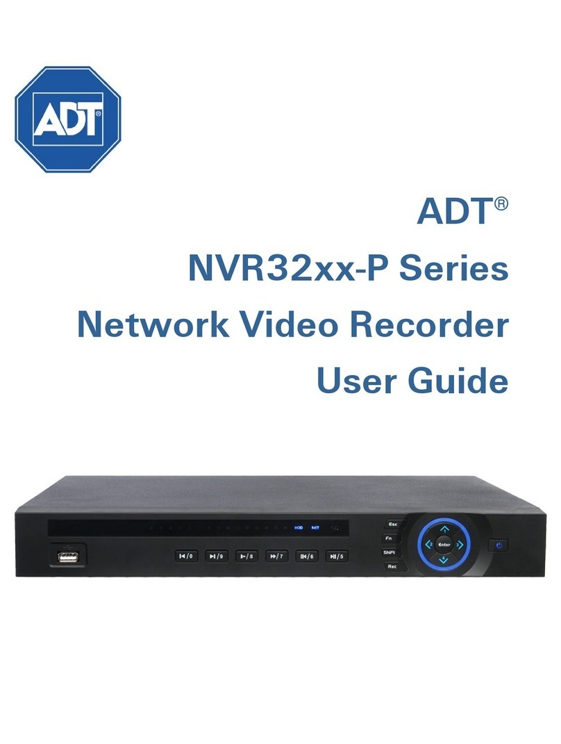
ADT NVR32xx-P Series User manual

ADT®
NVR32xx-P Series
Network Video Recorder
Quick Start Guide

Table of Contents
1NVR Overview................................................................................................................................... 1
1.1 Front Panel........................................................................................................................................................ 1
1.2 Rear Panel ......................................................................................................................................................... 3
1.3 Network Connection ...................................................................................................................................... 4
2GUI Operation ................................................................................................................................... 5
2.1 Start up .............................................................................................................................................................. 5
2.2 Login .................................................................................................................................................................. 5
2.3 Remote Device................................................................................................................................................. 7
2.3.1 IP Search................................................................................................................................................. 8
2.3.2 Add Device............................................................................................................................................. 8
2.3.3 IPC Config............................................................................................................................................... 9
2.4 Live Viewing (Preview).................................................................................................................................12
2.5 Manual Recording.........................................................................................................................................14
2.5.1 Manual Record ....................................................................................................................................14
2.5.2 Basic Operation ...................................................................................................................................14
2.5.3 Enable/Disable Recording................................................................................................................15
2.6 Schedule .........................................................................................................................................................16
2.6.1 Schedule Menu ...................................................................................................................................16
2.7 Search and Playback ....................................................................................................................................18
2.7.1 Other Functions...................................................................................................................................21
2.7.2 Smart Search .......................................................................................................................................21
2.7.3 Playback by Time ................................................................................................................................23
2.8 Logout / Shutdown ......................................................................................................................................24
3Web Service ................................................................................................................................... 25
3.1 Network Connection ....................................................................................................................................25
3.1.1 About PoE Address Setup, Operation and Allocation ................................................................25
3.2 Login ................................................................................................................................................................26
3.3 Preview Tab (Live Viewing).........................................................................................................................28
3.3.1 LAN Mode ............................................................................................................................................29
3.3.2 WAN Mode ..........................................................................................................................................32
3.3.3 Real-time Monitor ...............................................................................................................................33
3.4 Schedule .........................................................................................................................................................34
3.5 Recording........................................................................................................................................................37
3.6 Playback (Search)..........................................................................................................................................38
3.7 Logout..............................................................................................................................................................40
NVR32xx-P Series Quick Start Guide ii

1NVR Overview
1NVR Overview
This section provides information about front panel and rear panel.
1.1 Front Panel
The front panel is shown in Figure 1-1.
Figure 1-1
Refer to the following table for detailed information.
Group
No. Symbol Function
1
Power. Press and hold for three seconds to power up or shut down the NVR.
2 ^/ 1 Up arrow: Press to move the selection in the currently-active control up or to
increase the numeric value.
1: In text mode, press to enter the value 1.
</ 2
Left arrow: Press to move the selection in the currently-active control left.
During playback, click to control the playback bar.
2: In text mode, press to enter the value 2.
>/ 3
Right arrow: Press to move the selection in the currently-active control right.
During playback, click to control the playback bar.
3: In text mode, press to enter the value 3.
/ 4
Down arrow: Press to move the selection in the currently-active control down
or to decrease the numeric value.
4: In text mode, press to enter the value 4.
Enter Enter. Use to confirm the current operation, return to the default button or
select a menu item.
3 Esc Escape. Return to the previous menu or cancel the current operation.
During playback mode, press to restore real-time monitor mode.
Fn
(Function)
In one-window monitor mode: displays the PTZ control and image color
functions.
In motion detection setup: use with the direction keys to complete setup.
In text mode: toggles between numeric and alpha characters (lower/upper
case). Also serves as the Backspace function to delete the previous character
(to the left of the cursor) when pressed for 1.5 seconds.
In HDD management screen: switches between HDD recordings and other
information (Menu prompt).
NVR32xx-P Series Quick Start Guide 1

1NVR Overview
Group
No. Symbol Function
Shift Shift. Press to toggle between character types: number 0-9, upper case letter
or lower case letter.
Rec Record. Press to manually start/stop recording. Use the direction keys or
number keys to select the recording channel.
4 / 0
In playback mode: Press to playback the previous video.
In text mode: Press to select the number 0.
/ 9 In playback mode: Press to playback the next video.
In text mode: Press to select the number 9.
/ 8
In playback mode: Press to toggle between normal playback and various
slow play speeds.
In text mode: Press to select the number 8.
/ 7
In playback mode: Press to toggle between normal playback and various
fast play speeds.
In text mode: Press to select the number 7.
/ 6
In playback mode: Press to toggle between reverse playback and pause
playback modes.
In text mode: Press to select the number 6.
/ 5
In playback mode: Press to toggle between normal playback and pause
playback modes.
In text mode: Press to select the number 5.
5 1-16 Record Active indicators. Individual LEDs illuminate to indicate that a
channel is recording.
HDD HDD indicator. Glows to alert you of a hard disk error or that disk capacity is
below the specified threshold value.
NET Network indicator. Glows to alert you of a loss of the network connection.
IR IR receiver. Receives the signal from the remote control.
6 USB Port. Connects a USB storage device or USB mouse.
NVR32xx-P Series Quick Start Guide 2

1NVR Overview
1.2 Rear Panel
The 8-channel model NVR rear panel is shown in Figure 1-2.
Figure 1-2
Refer to the following table for detailed information.
Item Function
1 Grounding mount
2 Power switch
3 +12VDC input
4
Alarm input/alarm output/RS485 port
5 VGA Video output
6 RS-232 port
7 HDMI port
8 Network port; 10M/100M/1000Mbps self-adaptive
Ethernet
9 Audio input / output port *
10 USB port
11 Video output CVBS output
12
PoE ports. Built-in Switch supports Power over Ethernet
4 PoE port product supports 48V / 50W
8 PoE port product supports 48V /120W
13 +48 VDC input. Switch power port
Input 48VDC/1.04A (32-P) or 48VDC/2.5A (32-8P)
* ADT does not support Audio functions at this time
Note: When connecting the Ethernet port, use the crossover cable to connect the PC and use the
straight cable to connect to the switcher or router.
NVR32xx-P Series Quick Start Guide 3

1NVR Overview
1.3 Network Connection
Figure 1-3
NVR32xx-P Series Quick Start Guide 4

Hybrid Standalone NVR User Guide 2 GUI Operation
2GUI Operation
2.1 Start up
1. Connect the monitor, mouse, and power cable to the NVR.
2. Click the power button on the rear panel and then boot up the device.
3. Use the mouse to operate functions in the GUI.
2.2 Login
1. After the system has booted up, the Startup Wizard appears on the display monitor:
•Click Next Step if you would like to set up some basic system parameters.
or
•Click Cancel if you would like to skip the startup routine and go directly to the Login screen.
Figure 2-1
2. Enter your User Name and Password in the System Login dialog.
Figure 2-2
NVR32xx-P Series Quick Start Guide 5

Hybrid Standalone NVR User Guide 2 GUI Operation
The login consists of four accounts:
•User Name: admin. Password: admin. (administrator, local and network)
•User Name: 888888. Password: 888888. (administrator and local only)
•User Name: 666666. Password: 666666 (Lower authority user who can only use
monitor, playback, backup, etc.)
•User Name: default. Password: default (hidden user)
3. Use the USB mouse to complete the login.
a. Use the USB mouse to select one of the User Names from the Drop-down menu.
b. Click in the Password field. The virtual keyboard appears.
Figure 2-3
c. Toggle the ABC/ abc button or Shift key to select between upper or lower case letters.
d. Select the desired alpha/numeric character. It turns green and enters the Password field.
e. Repeat until all characters are entered.
f. Click Enter on the virtual keyboard. The keyboard disappears.
g. Click OK on the System Login dialog to enter.
Note: For security reasons, modify your password after your first login.
•Three (3) sequential login failures will result in a system alarm
•Five (5) sequential failures will result in account lock
NVR32xx-P Series Quick Start Guide 6

Hybrid Standalone NVR User Guide 2 GUI Operation
2.3 Remote Device
After login, set up your remote devices. To set up a remote device, open the dialog in one of the
following ways:
•In the main menu, click the Remote Device icon
•Right mouse-click and select Remote Device from the context menu
•For channels with no IPC connection, click the +icon in the center of the live view screen
The Remote Device screen opens, as in Figure 2-4.
Figure 2-4
NVR32xx-P Series Quick Start Guide 7

Hybrid Standalone NVR User Guide 2 GUI Operation
2.3.1 IP Search
Figure 2-5
1. Click this button to search for an IP address. This includes the device IP address, port, device
name, manufacturer and type.
2. Click the item name to refresh the display order.
3. Click the IP address and the system displays the IP addresses from small to large.
4. Click the IP address again and the icon appears. The system displays IP addresses from large
to small. Click other items to view their information.
2.3.2 Add Device
Click to connect to the selected device and add it to the Added Device list.
Note: The system cannot add a new device if the device you want to add has the same IP and
TCP port as another device in the list.
Show Filter button
Click this to display the specified devices from the added device.
Added Device field
•Edit: Click the button or double click a device in the list to change the channel setup.
•Delete: Select one device in the Added Device list and then click to remove it.
•Status: means that the connection is OK and means the connection failed.
Delete button
If you select a device on the Added Device list, and then click the Delete button, the device is
disconnected and then its name is removed from the list.
NVR32xx-P Series Quick Start Guide 8

Hybrid Standalone NVR User Guide 2 GUI Operation
Manual Add button
Click to add the IPC manually. The port number is 37777. The default user name is admin and
password is admin.
Figure 2-6
Channel: The dropdown list here displays unconnected channel numbers.
Select the channel number and then set the remote channel connection in the main screen (see
Figure 2-4). When you click OK, the system connects to the corresponding front end device of the
current channel on the interface.
2.3.3 IPC Config
Connect the IPC to the PoE port of the device rear panel. The system automatically connects to the
network camera.
Double click the on the IPC Config column to open the IPC setup interface, or else right mouse-
click and select IPC Config from the context menu.
Figure 2-7
NVR32xx-P Series Quick Start Guide 9

Hybrid Standalone NVR User Guide 2 GUI Operation
The IPC Config dialog opens.
Figure 2-8
Config File. Click the dropdown to select the network camera configuration file. The options include
day/night/normal/switch by period. If you select Switch by Period from the dropdown list, you
must set the Sunrise Time and Sunset Time.
Auto Iris. If enabled, the auto iris changes when the light intensity changes. If disabled, the iris is at
the max. The system does not add the auto iris function in the exposure control. This function is on by
default.
Mirror. Enable to reverse the video left and right limits. This function is disabled by default.
3D NR. Enable or disable the 3D noise reduction function.
Saturation. Use the slider to adjust monitor window saturation. The value ranges from 0 to 100. The
default value is 50. The greater the number, the greater the color intensity. This value has no effect
on the general brightness of the video as a whole. For the gray part of the video, distortion may occur
if the white balance is not accurate. Note that the video may not be attractive if the value is too low.
The recommended value ranges from 40 to 60.
Brightness. Use the slider to adjust monitor window brightness. The value ranges from 0 to 100.
The default value is 50. The larger the number, the brighter the video. You can use this function when
the video is too dark or too bright as a whole. Note that the video may become hazy if the value is too
high. The recommended value ranges from 40 to 60.
NVR32xx-P Series Quick Start Guide 10

Hybrid Standalone NVR User Guide 2 GUI Operation
Contrast. Use the slider to adjust monitor window contrast. The value ranges from 0 to 100. The
default value is 50. The larger the number, the higher the contrast is. You can use this function when
the whole video bright is OK but the contrast is not proper. Please note the video may become hazy if
the value is too low. If this value is too high, the dark section may lack brightness while the bright
section may be over exposed. The recommended value ranges from 40 to 60.
Sharpness. Use the slider to adjust the edge of the video. The larger the value, the clearer the edge
and vice-versa. The default value is 1 and the recommended value ranges from 0 to 15.
Flip. Use this function to rotate the display. The options include: None/Flip 180°/Clockwise
90°/Counter clockwise 90°. This function is disabled by default.
Light.Use this function to automatically adjust the exposure according to the ambient lighting.
Select from the dropdown list one of the following options: Disable/Enable/WDR/HLC.
Scene Mode. This profile sets the white balance mode. The default setup is auto. Select one of the
following from the dropdown.
•Auto: Automatically compensates the color temperature to ensure proper video color.
•Sunny: The threshold of the white balance is adjusted for bright sun.
•Night: The threshold of the white balance is set for night time.
•Customized: System supports your customized setup.
Day/Night Mode. This profile sets the video color or black and white mode. Select one of the
following from the dropdown.
•Color: The camera only outputs color video.
•Auto: The camera automatically selects color or black and white video according to device
setup (video brightness or whether IR light is detected).
•Black and White: The camera only outputs black and white video.
Delete. Select one device in the Added Device list and then click Delete to remove it.
Manual Add. Click this to add the IPC manually. The port number is 37777. The default user name is
admin and password is admin.
NVR32xx-P Series Quick Start Guide 11

Hybrid Standalone NVR User Guide 2 GUI Operation
2.4 Live Viewing (Preview)
After you log in, the system is in live viewing mode. You see the system date, time and channel name.
You can change the system date and time in the General Settings Menu (Main Menu > Setting >
General). To modify the channel name, go to the Display settings (Main Menu > Setting > Display).
Note: You can return to live viewing from any other mode by right-clicking the mouse or by
pressing the Esc key on the front panel or on the remote control.
Right –click the mouse and use the context menu to select the configuration you want to display.
View 1 for single channel or View X for multi-channel display. While in multi-channel mode, double
click on a channel to view it in single channel mode.
Note: To return to the previous menu, right-click the mouse or press the Esc key on the front
panel or on the remote control.
The following icons appear on the monitor screen.
TIP: During multiple-channel mode, you can change position of cameras on the screen. For example,
left-click on the camera on channel 1, drag it to the channel 8 position and release the mouse
button. Channel 1 and Channel 8 switch positions.
Live Mode Control Bar
Hover the cursor over the top center of the video in any channel. The live mode control bar appears.
The control bar automatically hides after 6 seconds of inactivity.
Figure 2-9
No. Name Function
1
Instant playback
Plays back the previous 5-60 minutes of recording for the
current channel. Click the Xat the bottom of the window to
stop the playback and return to real time. Navigate to Main
Menu>General to set real-time playback time.
2
Digital zoom
Zooms in on the current channel. The selected area displays
the icon; the free area is shown with .To zoom: left
mouse-click and drag to select a zone, and then release to
zoom in on the selected zone. After you have zoomed in the
zone, you can left mouse-click and drag to browse.
1
Recording mode
3
Video loss
2
Motion detection
4
Camera lock
1
4
3
2
6
5
NVR32xx-P Series Quick Start Guide 12

Hybrid Standalone NVR User Guide 2 GUI Operation
No. Name Function
3
Real-time backup
function
Backs up the video of the current channel to the USB device.
The system cannot backup the video of multiple-channels at
the same time.
The currently selected backup channel displays and the
free channel is shown with .
Once the backup started, the free channel is shown with the
icon.
4
Remote device
Click to open the remote device connection interface. Refer
to Shortcut Menu to Add Remote Device below for
detailed information.
5
Exit
Close the live mode control bar.
Instant Playback
The playback control supports the Play, Pause, and Exit and Drag functions.
•During the playback process, you cannot see the channel name and recording status of the
current channel. The channel name and recording status reappear after you click the Xto exit
playback mode.
•During the playback, you cannot switch the displayed channel or change current window-
display mode.
Note: The tour function has higher priority than the instant playback. You cannot control the
playback until the tour function has ended.
NVR32xx-P Series Quick Start Guide 13

Hybrid Standalone NVR User Guide 2 GUI Operation
2.5 Manual Recording
Note: You must have proper rights to implement the following operations.
2.5.1 Manual Record
This feature enables you to immediately begin recording. The manual record function overrides the
automatic recording settings. There are three ways for you to access the Manual Record screen.
•Right mouse-click and select Record
•Navigate to Advanced > Record in the Main Menu
•In live viewing mode, click the Rec button on the front panel remote control
Figure 2-10
2.5.2 Basic Operation
Highlight the ○icon to select corresponding channel for the desired mode. Alternatively, click All to
set all channels to the desired mode.
There are two modes of operation:
•Main stream, in the upper half of the dialog
•Extra stream, in the lower half of the dialog
There are three statuses:
•Schedule
•Manual
•Stop
Schedule.The channel records for the period you have set up (Main Menu > Setting > Schedule)
Manual.The channel records immediately until you select Stop. Manual recording has highest
priority.
Stop.All channels stop recording.
NVR32xx-P Series Quick Start Guide 14

Hybrid Standalone NVR User Guide 2 GUI Operation
2.5.3 Enable/Disable Recording
Current channel status is indicated by the corresponding icon:
○(filled) means the channel is in recording mode
●(empty) means that it is not in recording mode
Use the mouse or arrow keys to highlight the desired channel number. See Figure 2-11.
Figure 2-11
NVR32xx-P Series Quick Start Guide 15

Hybrid Standalone NVR User Guide 2 GUI Operation
2.6 Schedule
You can set the recording type and time in the Schedule screen.
2.6.1 Schedule Menu
In the Main Menu, click the Setting button and then select Schedule. The Schedule menu
appears. Highlight the box to select the desired functions. When completed, click OK. The system
returns to the previous menu.
The following describes the options on the Schedule screen.
Figure 2-12
Channel. Select the channel number that you want to schedule. Select All if you want to set for all
channels.
Pre-record. The system can pre-record the video before the event occurs into the file. The value
ranges from 1 to 30 seconds depending on the bit stream.
Redundancy. The system supports a redundancy backup function, which enables you to back up a
recorded file in two disks. Highlight Redundancy to activate this function. Before enabling this
function, you should set at least one HDD as redundant (Main Menu > Advanced > HDD
Management).
Note: This function is not available if there is only one HDD.
Snapshot. When selected, a snapshot photo is created at the scheduled interval.
Holiday. Click this box to enable a unique recording schedule for the days you established as
holidays in the General menu.
NVR32xx-P Series Quick Start Guide 16

Hybrid Standalone NVR User Guide 2 GUI Operation
Period. There are eight options: ranges from Saturday to Sunday and all.
Period. Select the day you want to schedule: Saturday to Sunday or All. Select Holiday to schedule
a unique recording schedule for the days you established as holidays in the General menu.
Period 1 -6. You can establish up to six separate recording ranges for the selected day and channel
number. For each period, enter the time of day in 24-hour format. For example, to record 10:30am to
2:00pm, enter: 10:30 -14:00.
Record Type. Select the type of recording to be created: Regular, Motion Detection (MD), Alarm and
MD with Alarm. For all types except Regular, recordings will only be created if the designated trigger
condition exists (motion detection and / or alarm) during the designated day and period.
At the bottom of the menu, there are color bars that indicate the type of recording:
Green indicates regular recording
Yellow indicates motion detection
Red indicates an alarm
Blue indicates motion detection with an alarm
To set up a regular (non-Holiday) recording schedule:
1. Select the recording channel from the Channel dropdown.
2. Select the recording day from the Period dropdown.
3. Select the recording time-of-day range(s) for the selected channel and day in the Period 1 –
Period 6 fields.
4. For each Period 1 –Period 6 field, click the box(es) for the type(s) of files you want to record:
Regular, Motion Detection and/or Alarm.
5. To record an additional 1-30 seconds prior to the scheduled time, enter the value in seconds in
the Pre Record box.
6. To enable a photo at the scheduled interval, click the Snapshot box.
To set a recording schedule for Holidays:
Note: You must first set up the Holiday function in the General menu.
1. Click the Holiday box to enable the days you established as holidays in the General menu.
2. Select the recording channel from the Channel dropdown.
3. Select Holiday from the Period dropdown.
4. Select the recording time-of-day range(s) for the selected channel and day in the Period 1 –
Period 6 fields.
5. For each Period 1 –Period 6 field, click the box(es) for the type(s) of files you want to record:
Regular, Motion Detection and/or Alarm.
6. To record an additional 1-30 seconds prior to the scheduled time, enter the value in seconds in
the Pre Record box.
7. To enable a photo at the scheduled interval, click the Snapshot box.
Note: Holiday settings have priority over non-holiday schedules. If the selected day is a holiday,
then the system records according to the Holiday setting. If it is not a holiday, the system
records according to the regular Schedule.
NVR32xx-P Series Quick Start Guide 17

Hybrid Standalone NVR User Guide 2 GUI Operation
2.7 Search and Playback
Click the Search button in the Main Menu, or else right mouse-click and select Search from the
context menu. The Search screen appears.
Figure 2-13
There are three file types. Refer to the following table for detailed information.
R: Regular recording file M: Motion Detection recording file A: External alarm recording file
No. Name Function
1
Display
window
The recorded file or snapshot picture is displayed here. The NVR supports 1, 4,
9, and16-window playback.
2
Search type
Select the desired file:
a. Highlight the ○for the file type: REC for recording or PIC for picture.
b. Use the drop-down menu to select the source. You can select to play from
the Read-Write HDD or from the peripheral device, if connected.
c. Click the Browse
button to view the record files in the root directory of the
peripheral device, and then select the file you want to play.
3
Calendar
In any play mode, click the date you want to see files for. The corresponding
record file trace appears in the time bar. If a date is highlighted in blue date, a
picture or file exists for this date.
1
6
8
12
9
3
4
2
10
11
5
7
NVR32xx-P Series Quick Start Guide 18
Table of contents
Other ADT Network Hardware manuals
Popular Network Hardware manuals by other brands

HIK VISION
HIK VISION DS-7764NI-M4 user manual

Black Box
Black Box ServSwitch Octet Series Technical bulletin

HIK VISION
HIK VISION LTN07128/256 user manual

HIK VISION
HIK VISION DS-9632NI-I8 quick start guide

HIK VISION
HIK VISION HiLook NVR-104H-D quick start guide

HIK VISION
HIK VISION iDS-9600NXI-I8/8FB Series user manual