Adtech Q2BYG403MD User manual

Adtech (Shenzhen) Technology Co., Ltd.
Q
Q2
2B
BY
YG
G4
40
03
3M
MD
D
D
Dr
ri
iv
ve
er
r
U
Us
se
er
r’
’s
s
M
Ma
an
nu
ua
al
l
Add: F/5, Bldg/27-29, Tianxia IC Industrial Park, Yiyuan Rd, Nanshan District, Shenzhen
Tel: 0755-26099116 Fax: 0755-26722718-616 Postal code: 518052
E-mail:export@machine-controller.com
Website: http://www.machine-controller.com

Q2BYG403MD Driver User’s Manual
-1-
Copyright
Adtech (Shenzhen) Technology Co., Ltd. (Adtech hereafter) is in
possession of the copyright of this manual. Without the permission of
Adtech, the imitation, copy, transcription and translation by any
organization or individual are prohibited. This manual doesn’t contain
any assurance, stance or implication in any form. Adtech and the
employees are not responsible for any direct or indirect data disclosure,
profits loss or cause termination caused by this manual or any
information about mentioned products in this manual. In addition, the
products and data in this manual are subject to changes without prior
notice.
All rights reserved.
Adtech (Shenzhen) Technology Co., Ltd.

Q2BYG403MD Driver User’s Manual
-2-
Chapter I. Safety Notice
To avoid personal injury and property damage, please read the following
safety information carefully before testing and using the Driver. Please
strictly follow the safety measures below:
¾Please read the User’s Manual carefully, and follow the safety rules
strictly.
¾If the input voltage of Q2BYG403MD is higher than 36V, please
check whether voltage of the Driver terminal is in safe range with a
multimeter after the power is cut off, and then connect the wire or
check, or else it may cause electric shock.
¾Do not connect the wires or insert/remove the terminal when the
Driver and motor are working, or else it may cause electric shock.
¾Do not open the shell of the Driver after the power supply is
connected or when the Driver is running, or else it may cause
electric shock.
¾To avoid personal injury or property damage, please ask qualified
personnel to operate the Driver.
¾Please follow the technical specification and electrical installation
standard during the installation. The Driver must be grounded
properly, and the cross-sectional area of the grounding cable should
be at least 1.25mm2.
¾Do not put any object in the Driver, or else it may damage the
Driver.
¾If the Driver has any failure, please send it to the maintenance
center. Disassembling the Driver without authorization or improper
operation may damage the Driver. It will violate the warranty if the
user opens the Driver shell without authorization.
¾To dispose of the Driver, please follow local regulations on
industrial waste disposal to avoid environment pollution.
※Statement:
If this Driver is applied to the machinery and equipment
directly related to personal safety (nuclear power control,
medical equipment, truck, train, aircraft, entertainment and
security equipment), it is required to install protection
equipment to avoid personal injury.
Electronic equipment isn’t permanently reliable. The equipment
must have sufficient safety measure, in order to protect the
safety of personnel and equipment in case of Driver failure. The
customer shall assume the losses due to machine failure or

Q2BYG403MD Driver User’s Manual
-3-
misoperation if the Driver is installed or used by the customer.
Chapter II. Product Overview
2.1 Introduction
Q2BYG403MD is a two-phase digital hybrid step motor Driver basing
on AC servo control. It is a new generation digital step motor Driver that
integrates advanced DSP control chip and unique control circuit. This
design can increase the integrity significantly, and reduce the size and
weight. The advanced current control algorithm is used to make it have
excellent performance, low vibration, low noise, less heat radiation and
high speed large torque output. Integrate undervoltage, overvoltage and
overcurrent protection, and the reliability is further improved. In
addition, this product also integrates RS-232 serial port communication.
Through PC installed with Driver software, the user can set the
parameters and test, which simplifies the production and test process.
2.2 Features
¾Allow driving 4, 6, 8 wires two-phase step motor
¾Ultra low vibration noise
¾Internal software uses micro-segmentation technology, which can
obtain high segmentation effect in low speed low segmentation
¾Integrate EMF compensation function, and the torque is constant
when the speed is increased
¾Parameter self-tuning
¾Current setting is convenient, and allow selecting freely between
1.2A and 4.2A
¾High precision segmentation, 1~256 optional
¾Pulse response frequency is up to 200KHz
¾Serial port communication, parameter is real-time adjustable,
meeting high performance requirement
¾In still state, the current decreases by half automatically, and the
maximum driving current is 4.2A/phase
¾Integrate protection for undervoltage, overvoltage, short circuit,
etc.
2.3 Application
The Driver is suitable for a variety of small and medium sized
automation equipment and instruments, such as: dispenser, marking
machine, cutting machine, engraving machine, labeling machine, plotter,
automatic assembly equipment, numerical control machine tool, etc. The
application is especially good in the equipment that users expect low

Q2BYG403MD Driver User’s Manual
-4-
vibration, low noise and high-speed.
Chapter III. Product Parameters and Installation
3.1 Parameters
Table 1: Electrical Parameters Table
Parameter Description
Input voltage Single power supply 24V~40VDC
Overvoltage
protection point
45VDC
Undervoltage
protection point
18VDC
Phase current
(A)
1.2, 1.6, 2.0, 2.4, 2.8, 3.0, 3.6, 4.2
Subdivisions 1, 2, 4, 8, 16, 32, 64, 128, 256, 5, 10, 25, 50, 100,
200
Control mode Pulse + direction
Type of
protection
circuit
Undervoltage, overvoltage and overcurrent
protection
Table 2: Operation Environment and Parameters Table
Cooling mode Natural air cooling
Occasion Avoid oil mist, metal powder
and corrosive gas
Environment humidity 30%~90%
Environment
temperature
0℃~50℃
Operation
environment
Vibration 5.9m/s2 max
Weight 250g
Size 118×5×34mm

Q2BYG403MD Driver User’s Manual
-5-
3.2 Port description
(1) Description of control signal interfaces
Signal Function Description
DR+
DR-
Direction
control signal
High/low voltage level state; requirement:
low voltage level 0~0.5V, high voltage level
4~5V, corresponding to two directions of
the motor The initial running direction of
the motor depends on the wiring of the
motor, and it can be changed by
interchanging any phase.
PU+
PU-
Pulse control
signal
Rising edge is valid; every time the pulse
signal rises from low to high, the motor
runs one step; requirement: low voltage
level 0~0.5V, high voltage level 4~5V, pulse
width ≥1.5us
EN+
EN-
Enable control
signal
Used to enable/release motor; EN+ is
connected to +5V, EN- is grounded, the
Driver will cut off the current of the motor
and enter the free state; at this moment, the
temperature rise and heating of the Driver
and the motor will reduce. If this function
isn’t used, make the signal terminal float.
(2) Motor and power interfaces
Signal Name Description
DC- DC power
grounding
Power supply grounding terminal
DC+ DC power
positive
terminal
Positive terminal of the power supply, single
phase DC power supply might be any value
between 24V and 45VDC, and the
recommended value is 36VDC.
B-
B+
B phase
winding Motor B phase winding coil
A-
A+
A phase
winding Motor A phase winding coil

Q2BYG403MD Driver User’s Manual
-6-
(3) RS-232 communication interface
Allow connecting to PC serial port through dedicated cable, modify and
save parameters, and monitor the running status through dedicated upper
computer commissioning software.
PIN No. Name Symbol Application
1 5V power
supply
positive
terminal
+5V The internal power supply of the
Driver is +5V, and is reserved for
external debugger
2 SCI
transmitter
terminal
TXD Serial data transmitter terminal
3 SCI receiver
terminal
RXD Serial data receiver terminal
4 NC Reserved
5 5V power
supply
grounding
GND Power point
(4) Driver status indicator
The green LED is power indicator. When the power supply of the Driver
is connected, this indicator is constantly on; when the power supply is
cut off, the indicator is off. The red LED is failure indicator. If there is
any failure, this indicator flashes repeatedly in a period of two seconds.
Please see the table below for the details of failure.
Alarm
No.
Flashing
times
LED status Description
1 1 Open circuit
failure
2 2 Undervoltage
3 3 Overvoltage
4 4 Overcurrent and
short circuit
failure

Q2BYG403MD Driver User’s Manual
-7-
3.3 Installation and wiring diagram
3.3.1 Machine installation size (mm)
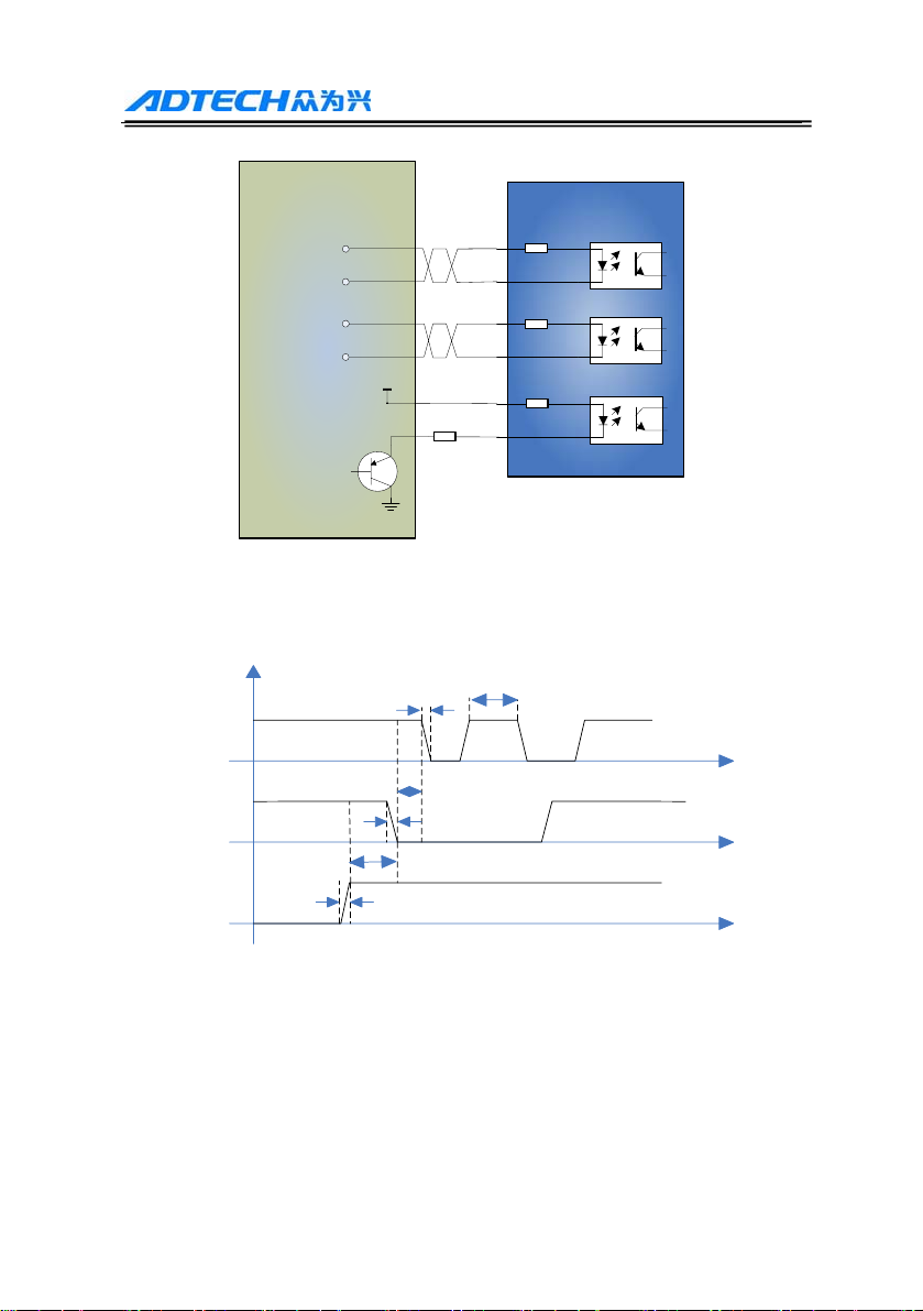
3.3.2 Connecting control wires
This Driver adopts differential interface circuit, builds in high-speed
optocoupler, the receiving frequency is higher than similar products,
interface is highly compatible, and anti-jamming capacity is strong
(especially differential output mode), and is applicable to NPN
open-collector output, PNP type output and differential mode output.
The connector circuit is shown below:

Q2BYG403MD Driver User’s Manual
-8-
(1) Common anode wiring: when VCC is connected to +5V, R is short
connected; when VCC is connected to +12V, R is 1KΩ; when VCC
is connected to +24V, R is 2KΩ;
(2) Common cathode wiring: when VCC is connected to +5V, R is
short connected; when VCC is connected to +12V, R is 1KΩ; when
VCC is connected to +24V, R is 2KΩ;
(3) Differential wiring: when VCC is connected to +5V, R is short
connected; when VCC is connected to +12V, R is 1KΩ; when VCC is
Q2BYG403MD Driver User’s Manual
-9-
connected to +24V, R is 2KΩ;
VCC
Controller Driver
GND
200欧
200欧
200欧
PU+
PU-
DR+
DR-
EN+
EN-
R
PUL+
PUL-
DIR+
DIR-
3.3.3 Control signal timing diagram
To avoid malfunction and deviation, PU, DR and EN signals should
meet certain timing requirement, as shown below:
3.3.4 Motor connection
If the Driver and motor are connected in different modes, the motor
running will have significantly different effect. Generally, the supply
voltage of the Driver determines the high speed performance of motor
running. The higher the voltage is, the larger the high speed torque is.
Current value determines the output torque of the motor. The higher the
current is, the larger the output torque is. However, if the supply voltage
is high, the vibration during low speed running is also large; if the

Q2BYG403MD Driver User’s Manual
-10-
current value is high, the heating of the Driver and motor will be serious.
Therefore, the user needs to select appropriate connection accordingly to
get desired effect. The following wiring modes are available.
8-wire
motor
A+
A-
B+ B-
4.8-wire serial connection
4-wire
motor
A+
A-
B+ B-
1.4-wire motor connection
6-wire
motor
A+
A-
B+ B-
2.6-wire serial connection
BC
AC 6-wire
motor
A+
A-
B+ B-
3.6-wire center point connection
BC
AC
8-wire
motor
A+
A-
B+ B-
5.8-wire parallel connection
4-wire motor: only one connection is available, and the current should
be no higher than the rated current.
6-wire motor: serial and center tap connection are available. Serial
mode has large torque at low speed, but it can’t rotate fast as connected
to center tap and the current should be set to 70% of the rated current;
center tap mode has high speed performance and the current should be
no higher than the rated current.
8-wire motor: serial and parallel mode are available. Serial mode has
large torque at low speed and small torque at high speed, and the current
should be set to 70% of the rated current; parallel mode has excellent
performance at high speed, and the current should be set to 1.4 times of
the rated current.
: When the motor is connected to the Driver, please make sure that
the power supply has been turned off. Make sure that the motor leads
not used can’t contact other objects. When the Driver is electrified, do
not disconnect the motor directly. Do not connect the motor lead to
ground or power supply.

Q2BYG403MD Driver User’s Manual
-11-
3.3.6 Wiring requirements:
(1) To prevent the Driver from interference, it is recommended to use
shielded cable for signal control, and short connect the shielding layer
and ground wire; unless otherwise specified, ground one end of the
shielding cable that controls signal cable: ground the upper computer
end of the shielded cable, and leave the Driver end of the shielded cable
floating. In the same machine, only one point can be grounded; if the
ground wire isn’t true, it may cause serious interference, and the
shielded layer isn’t connected at this moment.
(2) Pulse and direction signal wires can’t be bundled together, and keep
at least 10cm clearance, or else the motor noise will interfere with the
pulse and direction signal, cause inaccurate motor positioning, instable
system and other faults.
(3) If one power supply is provided to several Drivers, it is required to
connect them in parallel, rather than in chain.
(4) Do not insert or remove the strong current CN1 terminal of the
Driver when the power is still on. The motor still has large current
through the coil even when it is stopped, and inserting/removing CN1
terminal will cause instantaneous induced EMF and burn out the Driver.
(5) It is strictly prohibited to add tin to the lead head and connect to the
terminal, or else the terminal may be damaged due to large contact
resistance and overheating.
(6) The wire connector can’t expose out of the terminal, to avoid
damaging the Driver due to short circuit.
3.5 DIP switch setting
Q2BYG403MD step Driver uses 8-bit DIP switch to set the output
current, subdivision precision, quiescent current and self-tuning of
parameters. The front view of DIP switch is shown below:
Fig. (2) Front View of DIP Switch

Q2BYG403MD Driver User’s Manual
-12-
(1) Current setting (Ipeak= Irms×1.4):
Irms(A) SW1 SW2 SW3
1.2 OFF OFF OFF
1.6 ON OFF OFF
2.0 OFF ON OFF
2.4 ON ON OFF
2.8 OFF OFF ON
3.0 ON OFF ON
3.6 OFF ON ON
4.2 ON ON ON
(2) Subdivision setting:
Subdivisions SW5 SW6 SW7 SW8
1 OFF OFF OFF OFF
2 ON OFF OFF OFF
4 OFF ON OFF OFF
8 ON ON OFF OFF
16 OFF OFF ON OFF
32 ON OFF ON OFF
64 OFF ON ON OFF
128 ON ON ON OFF
256 OFF OFF OFF ON
5 ON OFF OFF ON
10 OFF ON OFF ON
25 ON ON OFF ON
50 OFF OFF ON ON
100 ON OFF ON ON
150 OFF ON ON ON
200 ON ON ON ON
(3) Quiescent half current setting
Set half/full current (SW4=OFF: half current; SW4=ON: full current).
For self tuning setting of parameters, move the SW4 switch once in two
seconds to realize the self tuning of motor parameter and Driver
parameter.

Q2BYG403MD Driver User’s Manual
-13-
Chapter IV. FAQ
4.1 Motor selection
Q2BYG403MD is suitable for 4, 6, 8-wire two phase hybrid step motor.
However, to make the motor have optimized running effect, it is usually
required to select appropriate motor to match the Driver.
(1) It is known from the torque-frequency characteristics of the step
motor that the output torque decreases along with the increase of
motor speed. Generally, at light load, the maximum working speed is
below 15 rev/sec, and at heavy load, the maximum working speed is
about 10 rev/sec. If the system has a higher requirement on speed,
please select servo motor.
(2) If step motor is selected, please select the model of appropriate torque
according to the load.
(3) During working, it is allowed to change the system transmission ratio
through gear box and synchronous belt, and thus adjust the
relationship between output torque and load speed.
(4) Increase the supply voltage of the step motor to improve the working
speed of the motor; increase the working current of the step motor to
improve the torque of the motor; increase the subdivisions of the step
motor to improve the precision of motor, and also improve the
stability of the motor, and reduce vibration and noise.
4.2 Typical wiring
The control signal wiring of the controller and Driver can be one of the
three wiring modes shown in 3.3.2. The power supply and motor wiring
is shown below:
Q2BYG403MD
Driver
DR+
DR-
PU-
PU+
EN+
EN-
DC-
DC+
B-
B+
A-
A+
Cotroller
DC power
supply
24-40VDC

Q2BYG403MD Driver User’s Manual
-14-
4.3 Troubleshooting
Failure Possible reason Solution
Power supply system
has error
Check the power supply circuit
Power indicator is
off Supply voltage is low Increase the supply voltage
Motor wire isn’t
connected properly
Check the wiring
Voltage is too high or
too low
Check the power supply
Alarm indicator is
on
Current is too large Check the power supply
The power supply isn’t
connected
Check and connect the power
supply
Motor wiring error Check the wiring
Protection circuit works Reconnect the power supply
Enable signal is low Disconnect EN signal
Current setting is too
low
Reset the current
Subdivision is too small Reset the subdivisions
Motor doesn’t run
No pulse signal input Adjust the pulse signal
Subdivision has error Reset the subdivisions
Motor load is too high Change the motor or increase the
current
Position is
inaccurate Motor wire bad contact Check and connect the wires
properly
Direction signal isn’t
connected properly
Interchange two wires in the
winding of same phase
Motor rotation is
wrong Motor wire is
disconnected
Check and connect properly
Acceleration is too high Reduce the acceleration
Motor torque is too
small
Select appropriate motor
Motor
acceleration
stalled Maximum speed is too
high
Reduce the maximum speed
☻Prompt
Dear customers:
Thanks for purchasing the step motor Driver of our company. We hope
that the excellent performance, superior quality and high
performance-price ratio of our products can accomplish your value. If
there is any problem, please don’t hesitate to contact us. Please call our
hotline 0755-26099116 or E-mail us: export@machine-controller.com
Table of contents
Other Adtech DC Drive manuals

Popular DC Drive manuals by other brands


KSB
KSB PumpDrive 2 Eco Installation & operating manual

ABB
ABB Baldor BC200 Installation & operating manual

TMB
TMB ProPlex IMS Universe Drive IP65 quick start guide

Siemens
Siemens FLENDER H3LV Assembly and operating instructions

Invertek Drives
Invertek Drives Optidrive ODE-2-11005-1H01 Series user guide

YASKAWA
YASKAWA VS MINI J7 Replacement instructions

Allen-Bradley
Allen-Bradley powerflex 700 quick start guide

phytron
phytron phyMOTIONT I1AM02.1 TRANSLATION OF THE GERMAN ORIGINAL MANUAL

Parker
Parker 890CS product manual

Masterflex
Masterflex L/S MFLX07528-40 operating manual

YASKAWA
YASKAWA E-V-SD Series user manual

Danfoss
Danfoss VLT HVAC Drive FC 102 installation guide