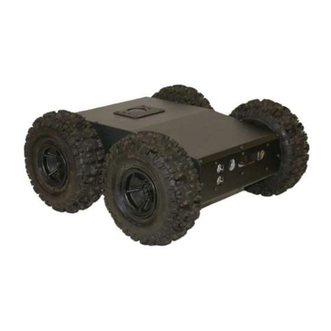
Adtech ADT-RC400 User manual

User Manual
(Servo Debugging for Pre-motion)
ADTECH Robotic Drive System
ADT-RC400

Information of manual
I
Information of Manual
This manual is edited By ADTECH (SHENZHEN) TECHNOLOGY CO., LTD.
The editors of this manual: Jipeng Yang and Yan Chen.
The version of this manual: V1.1.1
Copy Right
All parts of this manual, property right owned by ADTECH (Shenzhen) Technology
Co.,LTD (hereinafter referred to as) to all, without permission, no unit or individual is not any
imitation, copying, copying or translation. Position this guide without warranty of any kind,
expressed or implied. As mentioned by this manual or its product information, arising out of,
directly or indirectly, information flow, loss of interest or career ending, and its employees
will not take any responsibility. In addition, the products and information mentioned in this
manual are for reference only, subject to updates without notice.
All rights reserved, do not reproducing.
ADTECH (SHENZHEN) TECHNOLOGY CO., LTD.

II
Range of Manual
This is the first manual of QC400 drive robotic control system concluding full
description, drive control for the initial users, to help users select reasonable motor type;
followed this specification for drive control electrical wiring between the machine and the
robot in detail.

III
Precautions
※Transport and storage
Product package iteration of no more than six
It is not available in the product box on the climb, stand or place heavy objects
Cannot use drag the cables attached to the product or handling products
No collision, scratching the Panel and display screen
Product box should avoid wet, dry and the rain
※Opening inspection
After opening the packaging please confirm whether you purchased the product
Check whether the products in transit damage
Control list identifies whether the part is complete, there is no damage
Product model, lack accessory or transport damage, please contact with me
※Wiring
To participate in connections and inspection personnel must have the appropriate
skills for professionals
Products must be reliable earthling, grounding resistance should be less than 4
ohms; you cannot use the neutral (zero line) instead of ground
Wiring must be properly and firmly, so as not to lead to product failure or
unexpected consequences
And surge absorption diode must be connected in accordance with the regulations
are connected with, otherwise you will damage
Plug plugs or open the front of the chassis, you must cut off the power supply
※Maintenance
Must cut off the power before repair or replacement of components
Should check the fault when a short circuit or overload occurs, troubleshooting
before they can restart
Cannot pass off frequently, if required to re-apply after a power failure, separated by
at least 1 minute
※Others
Do not open the Cabinet without permission,
Long when not in use, please cut off the power.
To pay special attention not to let dust, iron powder into the controllers.
Output relay if the use of solid state relays shall be freewheeling diode in parallel in
the relay coil. Check if the power supply meets the requirements, put an end to the
controller is burnt out.
Life of the controller temperature has much to do with the environment, if the
processing temperature is too high, please install the cooling fan. Controller working

IV
ambient temperature range between 0 ℃-60 ℃.
To avoid high temperatures, humidity, dust or corrosive gas environments.
Shake strongly to add buffer rubber Rails.
※Maintenance
Under normal conditions of use (environment conditions: average 30 ℃, load 80%,
running 12 hours a day), please press the following items for routine checks and regular
checks.
Daily Check
Daily
Recognition of environmental temperature,
humidity, dust and foreign bodies
●There are no abnormal vibrations,
sound
●Ventilation holes without being
clogged with yarn and other
Period Check
1 year
●Substantial part is loose or not
●Terminal block damage
Since the robot system is more complex, dangerous. The manual records and
security-related precautions, please strictly observe transactions as recorded.
Safety Precautions and mark
Mark
Mark meaning
Danger
Use wrongly, it will lead to a dangerous situation,
causing serious injury or death
note
Use wrongly,It will lead to a dangerous situation that
may cause personal injury or damage to equipment
which caused material damage.
Ban
Absolutely unenforceable
!
Forcibly
Must be implemented
Danger
Please do not use this system in the flammable and explosive environment.

V
Likely to cause injuries or fire.
Please follow the instructions drawings or wiring.
Prone to electrical shock and damage the
motor.
In an energized state, do not arbitrarily pull the plug, in the operating state; do not touch
the robot operation site.
Easy electric shock, causing personal injury.
Energized state, not for wiring, maintenance and other operations, be sure to power at
least 5 minutes before proceeding.
Easy electric shock.
Please be sure to take a reliable grounding between the drive and the robot body.
When the fault occurs easily lead to electric
shock, fire incident, easy to trigger errors.
Non professional personnel, please do not open the drive and control one machine shell,
please do not use hand to touch the drive and control of internal components
Easy electric shock
In the case of power, do not touch the power plug of the integrated machine.
Easy electric shock.
Please do not damage, the weight of cable or cable suspended load
Easy electric shock

VI
The energized state, do not plug the drive terminal machine control on
Easy electric shock and short circuit
Running state, do not pull out the terminal on the one machine
Easy electric shock and short circuit

VII
Attention
Please pay attention to the drive and control of the motor and the heat of the peripheral
equipment.
Easy to burn.
When a fault occurs, the power supply is cut off, the cause is identified and removed, and
the low speed running equipment should be removed.
If there are adverse factors, easy to cause
false action.
When using the controller and the robot body, it cannot exceed the scope of its
specification.
Easily cause damage to the product.
When the robot is moved, it needs to be fixed with the attached fixed tool.
To prevent the lifting arm, due to accidents.
The installation, operation, maintenance and inspection before, be sure to read the
instructions carefully, according to the operating instructions in step.
Easy electric shock, fire
Power supply voltage, power capacity must be specified by the company's specifications.
Improper use of equipment failure, easy to
cause a fire.
Please correct use of the correct control of each other to drive one machine and robot.
Prone to failure

VIII
Should be regularly on the implementation of the robotics drive system maintenance and
inspection operations.
Neglect of maintenance and inspection is an
important cause of equipment failure and
accidents.
Please do not put heavy objects on the product.
Easily cause damage
Please correct the wiring in the instruction manual.
The wrong wiring way is easy to cause the
robot or the drive control one machine
damage or cause a fire.
When an exception occurs, please stop.
Easy electric shock, personal injury, fire
Need to repair, please contact our company, please do not disassemble.
Easy cause trouble.
Do not impact
Easy cause trouble

IX
Ban
In the course of the robot's movement, no person is allowed to stand in the robot action
area.
There will be a major injury accident.
Equipment to prevent the movement of the robot in the workplace.
When the device is abnormal, it is easy to
cause damage.
The emergency stop switch on the handheld display device is prohibited.
Robots in an accident or is not running
properly, you need an emergency stop
switch, stop operation of the equipment.
There is no correct operation of the prohibition on the instruction manual.
Incorrect operation will bring about the
incorrect operation of the equipment.
Other personnel outside the operating personnel to close to the equipment
Touching the dangerous area can cause the
injury or the major accident.
When an accident, to cut off the power supply, clear reasons.
When there are bad reasons, the robot may
have a wrong action, causing adverse
consequences.
Users are prohibited to carry out parts of the exchange and transformation.
Will reduce the system performance and
may malfunction

X
Please do not remove the cleaning.
Easy to cause fire, easy to get electric shock.
Please don't make the product stored in the leaks, water, and other harmful gases in the
environment.
Prone to failure
Forced
!
Please keep the sun out of the sun.
!
Easy cause trouble
Please use the specified range.
!
Easily cause burn, failure
Equipment protection cover must be shut off during operation.
!
Open the protective cover will have electric
shock, the disabled.
Operator to go through the full training.
!
Incorrect operation will cause the device to
malfunction, resulting in disability or major
disaster.
If the robot is not in accordance with the specified direction of action, press the emergency
stop, stop the equipment operation.
!
Accidents and failures.
Power cord must be used with the specified wire.
!
Prone to fire and failure.

Notification
XI
Safety regulations
●Before starting the run, we need to know all the tasks of robot in accordance with the
program to be executed;
●Robots run in automatic mode, personnel are not allowed to enter any of its
movement reach areas;
●When the need for programming, testing and maintenance work, the robot shall be
placed under manual mode;
●When debugging personnel enter the robot work area, he shall carry a teach pendant,
to prevent others from malfunction;
●When the robot does not work for a long time, the fixture should not place items; it
shall be empty machine;
●After a power outage, the main power on the robot should shut down timely, and
remove the clamp on the work piece.

Contents
XII
Contents
INFORMATION OF MANUAL...........................................................................................................................I
1SOFTWARE INSTALLATION.................................................................................................................1
1.1 INSPECTION BEFORE DEBUGGING .........................................................................................................1
1.2 QUICK START........................................................................................................................................1
1.3 INTRODUCTION OF THE PC SUITE..........................................................................................................3
2 COMMUNICATION CONNECTION ....................................................................................................8
3 PARAMETER MANAGEMENT...........................................................................................................11
3.1 UPLOAD PARAMETERS ........................................................................................................................11
3.2 DOWNLOAD PARAMETERS ..................................................................................................................12
4 CONFIGURATION OF BASIC PARAMETER...................................................................................16
4.1 CONFIGURATION OF MOTION MODE ...................................................................................................16
4.2 CONFIGURATION OF MOTOR’S PARAMETERS.......................................................................................17
4.3 CONFIGURATION OF PROTECTION PARAMETERS .................................................................................20
5 GAIN TUNING........................................................................................................................................24
5.1 TEST OF ENCODER BEFORE TUNING....................................................................................................24
5.2 COMMUTATION TUNING......................................................................................................................25
5.3 GAIN TUNING......................................................................................................................................28
5.3.1 Tuning of Current Loop..............................................................................................................29
5.3.2 Tuning of Velocity Loop..............................................................................................................38
5.3.3 Tuning of Position Loop.............................................................................................................45
6 PRE-MOTION.........................................................................................................................................50
7 ERROR ALARM OF SERVO AND HANDLING................................................................................53

Debugging Process
XIII
You must tune some servo parameters for pre-motion before using QC400 robotic drive
system. If servo parameters have tuned before, you can download these parameters to drive
system directly, and then have a pre-motion. If not, you have to tune servo parameters with
following steps strictly.
Downloading
Parameters
Communication
Software Installation
Run
Commutation
Curr\Vel\Pos
Tuning
Parameters
Setting
Communication
Software Installation
Run
With Servo Parameters
Without Servo Parameters
【Notice】
In the following figures, marks such as
4321
represent execution order.

Servo Debugging for Pre-motion
1
1.Software Installation
1.1 Inspection before Debugging
For security and efficiency, some aspects should be checked before debugging.
(1) State of servo motor
Check fixed parts of motor to make sure that all the wires are connected well.
Check the encoder wire and power wire of motor whether they are connected
correctly.
(2) State of robotic drive system
Check the internal power of QC400 to make sure that it has the normal power
supply.
Make sure that the encoder and power wire are connected well with QC400.
1.2 Quick Start
This part is a quick tour of the PC suite to explain some of the basic concept and get
used to navigating the software. This part can be done without a controller or a running
system.
Operating System
Windows 7 32 位
Windows 7 64 位;
Windows XP
Screen Resolution
The PC Suite requires display with a resolution of at least
1280 768
. Even with
1280 768
resolution, you will need to “Auto-hide”the windows task bar to conveniently
access the main menu. Resolutions of
1280 900
or higher are recommended.
Installation
The steps of Installation are shown in the following diagram.

Servo Debugging for Pre-motion
2
Tes t whet her th e
drive is installed
s uc ce s sf u ll y b y
【Help *1】
Close the Antivirus Software
of the Computer
Unzip Debugging
Package
Install Microsoft .NET
Framework4.0
Install Drive
Program(Serial
Drive、USB Drive)
Double Click
”AgitoPCSuite.exe”
【Help*1】
Normally, we can test whether the drive is installed successfully by checking the
existence of terminal. You need to re-install the serial and USB drives if the terminal can not
be detected. The specific approaches of examining are listed based on your operating system:
(1) Window XP system: Right click “My Computer”icon
Left select “Device
Administration”
Left select “Terminal”(To check COM port);
(2) Window 7 System: Right click “Computer”icon
Left select “Device
Administration”
Left select “Terminal”(To check COM port).
Depending on your PC’s security settings, you may receive a request for permission (for
first time execution of the installed software). Please allow PC Suite access to the requested
resources.
Two applications will open:
QX Communicator

Servo Debugging for Pre-motion
3
QX PC Suite
Leave both of them open. The OX PC Suite firstly opens with a warning message.
Please read it carefully and click OK.
Notice
The software interface may appear incomplete phenomenon if screen resolution is too
low. Do not close the communication interface when using debugging software.
1.3 Introduction of the PC Suite
The QX PC Suite window of QC400 Robotic Drive system as follows:

Servo Debugging for Pre-motion
4
Main Menu Information
Current Tool
Favorite
Tool
Recent Tool
Operating Button Language
The window is made of a frame and the contents. The frame always has the same parts
and the contents changes according to the tool selected by the user. Then several specific
parts will be introduced.
The operating button performs the following functions:
Save all parameters to the controller Flash memory.
Load all parameters from the controller Flash memory.
Kill all the axes and servo off.
Select axis drop down menu.
Main menu
In the main menu you can see all available tool sets, and each is represented by an icon
at a given color. The tool sets are arranged from left to right by the most probable order
which they should be used when setting up a new system. Clicking the below an icon of a
tool set at the main menu, the sub-menu will display. The detail function of each tool will be
introduced in the later chapter.

Servo Debugging for Pre-motion
5
Left menu bar
The left menu bar is used to personalize the display to the convenience of the user and to
enable easy and fast access to frequency used tools. The lasted tools and favorite tools are
displayed in the left menu bar. The latest tools are automatically displayed in the “recent”
menu and the favorite tools are displayed by right clicking button on any tool to pin them.
At the same time, the icon of current tool is also appeared on the upper left corner of the
PC Suite frame. Right click on this icon to invoke a context sensitive menu, which includes
“Pin to Favorite”, “More Info”, “View: Terminal Only”, “View: Terminal with Status and
“View: Terminal with Statuses and Data Recording”. Different views may be required
depends on the user and the specific task.
Current tool

Servo Debugging for Pre-motion
6
Pin to Favorite: Set the current tools to the favorite ones.
More Info: It contains more information;
View: Terminal Only —— Only terminal is displayed;
View: Terminal with Statuses —— Only statuses are displayed on the terminal;
View: Terminal with Statuses and Data Recording —— Upper-left of the frame
displays statuses, below-left displays terminal and right displays data recording.
Favorite tools
Right-click them, four operations can be performed as follows:
Recent tools
They have the similar operations as the favorite tools’.
Info
You can click “Info”(at the button-right corner of the PC Suite frame) to receive
information about QX PC Suit. The information of PC Suite, communication channel and
connected controller will be displayed in this frame.
Other manuals for ADT-RC400
1
Table of contents
Popular Robotics manuals by other brands
OTTO MOTORS
OTTO MOTORS 1500 Fast Charger V1.2 Operation and maintenance manual

bionicbird
bionicbird Metabird instruction manual

Prince
Prince Play The Best T8561 owner's manual
Universal Robots
Universal Robots OEM UR5 installation guide

OSOYOO
OSOYOO Omni-wheel manual
SMC Networks
SMC Networks JMHZ2-16D-X7400B-TM Operation manual
Omron
Omron Cobra 350 ePLC Quick setup guide
Universal Robots
Universal Robots 3PE Teach Pendant installation guide

TEACH TECH
TEACH TECH TTR-892 Assembly & instruction manual
Sony
Sony Aibo ERS-7 quick guide
WEISS ROBOTICS
WEISS ROBOTICS IEG Series Mounting and operating manual
adept technology
adept technology Viper s650 user guide

