ADTX ArrayMasStor K Series Guide

Ó2001 Advanced Technology and Systems Co., Ltd.
13715 Alton Parkway
Irvine, CA 92618
Tel (949) 583-2993
ArrayMasStor ÒKÓ Series
Installation Manual and Users Guide

ArrayMasStor K Series
ÒInstallation Instructions and Procedures.Ó
Copyright ÓAdvanced Technology and Systems Co., Ltd., 11/2001 Rev. A
Trademarks and Trade name that may appear within this document are the property of their respective owners.
Introduction ..............................................................................................................................2
K-SERIES PRODUCT FEATURES..................................................................................................2
Unpacking the RAID system ....................................................................................................3
PACKING LIST ..........................................................................................................................3
Installing the RAID system....................................................................................................... 3
SCSI TERMINATION .................................................................................................................4
Installing the Front panel cover ............................................................................................... 5
HOST SCSI REQUIREMENTS......................................................................................................5
Operating the RAID system ..................................................................................................... 5
Front panel status indicators (LEDs).......................................................................................7
Front ÒFresh airÓ intakes .........................................................................................................8
Rack mounting the RAID unit .................................................................................................8
Identifying rear panel components .......................................................................................... 9
Product Components ..............................................................................................................10
RAID CONTROLLER ............................................................................................................... 10
IDE DRIVE BAYS AND DRIVE TRAY ASSEMBLIES .................................................................... 10
POWER SUPPLIES .................................................................................................................... 10
FANS...................................................................................................................................... 10
ENCLOSURE............................................................................................................................ 10
RAID Overview ...................................................................................................................... 11
Non-RAID Storage ............................................................................................................. 11
About RAID levels .................................................................................................................. 12
RAID 0.................................................................................................................................. 12
RAID 1.................................................................................................................................. 12
RAID 1 (0+1) ..................................................................................................................... 13
RAID 3.................................................................................................................................. 13
RAID 5.................................................................................................................................. 13
Spare drives in RAID configurations..................................................................................... 14
RAID Rebuilding .................................................................................................................... 14
Removing a Drive from the RAID system (with power off).................................................. 15
Removing a Power Supply from the RAID system (with power off) ....................................17

ArrayMasStor K Series
ÒInstallation Instructions and Procedures.Ó
Copyright ÓAdvanced Technology and Systems Co., Ltd., 11/2001 Rev. A
Trademarks and Trade name that may appear within this document are the property of their respective owners.
REDUNDANT POWER SUPPLIES ................................................................................................ 17
RAID controller functions...................................................................................................... 19
RAID CONTROLLER BUTTON FUNCTIONS................................................................................. 19
RAID CONTROLLER CONNECTORS.......................................................................................... 20
Using the RAID Controller Functions ................................................................................... 21
BASIC FEATURES .................................................................................................................... 21
Front Panel Ready Mode.................................................................................................... 21
Front Panel Configuration Options ....................................................................................... 22
Auto RAID Setup.................................................................................................................... 23
ADVANCED FUNCTIONS .......................................................................................................... 23
Selecting RAID Levels ............................................................................................................ 25
Adding Drives to the RAID system ........................................................................................25
Troubleshooting...................................................................................................................... 26
CONTROLLER ......................................................................................................................... 26
Problems at Startup............................................................................................................ 26
Other Problems ..................................................................................................................26
ENCLOSURE............................................................................................................................ 26
Power Supplies................................................................................................................... 26
Fans ................................................................................................................................... 27
Drive Trays ........................................................................................................................ 28
LEDs.................................................................................................................................. 28
Ports .................................................................................................................................. 28
Replacement Parts.............................................................................................................. 28
Drives ................................................................................................................................ 28
Spare Installed ................................................................................................................... 28
No Spare Installed..............................................................................................................29
NOTES AND WARNINGS........................................................................................................... 29
Remote Monitoring and Management ................................................................................... 31
RS-232C INTERFACE.............................................................................................................. 31
ADTX MasStor K-Series Specifications ................................................................................32

ArrayMasStor K Series
ÒInstallation Instructions and Procedures.Ó
Copyright ÓAdvanced Technology and Systems Co., Ltd., 11/2001 Rev. A 2
Trademarks and Trade names that may appear within this document are the property of their respective owners.
Introduction
Thank you for purchasing your new ArrayMasStor K-Series RAID system from ADTX¨. This
high quality data storage system offers very high performance with Òstate-of-the-artÓ reliability. It
has been rigorously tested to ensure trouble-free operation and long life.
The K-Series is a SCSI-to-IDE RAID system with drive bay space for six EIDE disk drives. The
system can be used with virtually all contemporary SCSI equipped host systems.
As a RAID data storage system, it provides both increased drive access speed and fault tolerance
(i.e., one drive in the system can fail without affecting its data integrity or operations). The system
provides additional fault tolerance with dual, redundant, hot-swappable fan/indicator modules and
power supplies. All of its RAID functions are performed by a PowerPCÒRISC CPU with high-
speed SDRAM and flash memory firmware.
Its built-in hardware RAID controller employs sophisticated drive failure management capabilities
that allow automatic reassignment of reserved blocks when a bad drive sector is encountered during
write operations. Hot swapping of the drives is supported through automatic disconnection of a
failed drive and the automatic detection of a spare ÒreservedÓ drive. If a drive fails, the system
supports the automatic rebuilding of data in the background, allowing host operations to continue.
Amazingly, failure recovery operations are completely transparent to the host system.
The K-Series system is so easy to use, that it can be installed, configured, and deployed by users
without intimate knowledge of RAID systems. ItÕs built-in automatic RAID setup feature can
perform all of the setup, ID assignment, and configuration tasks needed for regular operation.
K-Series Product Features
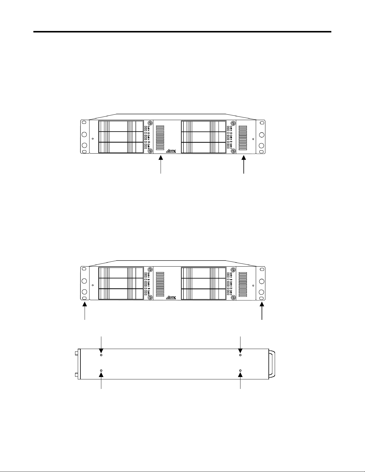
qCompact (2U) rack mount enclosure
qSelf-contained operation. No special host software needed
qUltra160 SCSI host interface with transfer rates up to 160Mbyte/sec.
qComprehensive RAID level support: 0, 1(0+1), 3, 5
qSupports up to 6 EIDE ATA-66/UDMA-66 (and ATA/UDMA-100) disk drives
qCompatibility with most contemporary 3.5" x 1" high EIDE disk drives
qEmploys hot-swappable drive tray assemblies
qIncorporates a Òbuilt-inÓ LCD control panel and status display
qProvides up to 64MB of cache memory
qEasily upgradable firmware (Flash ROM)
qAutomatic RAID Setup function for easy installation
qDual, redundant, hot-swappable power supplies
qDual, independent, front accessible, hot-swappable cooling fan/indicator modules
Note: The K-Series RAID system only supports IDE disk drives. It is not compatible with SCSI
disk drives.

ArrayMasStor K Series
ÒInstallation Instructions and Procedures.Ó
Copyright ÓAdvanced Technology and Systems Co., Ltd., 11/2001 Rev. A 3
Trademarks and Trade names that may appear within this document are the property of their respective owners.
The following sections have been provided to help you set up your new RAID system and have it
operating as quickly as possible. Please follow these instructions carefully. By doing so, you will
be able to benefit from the systemÕs many features and benefits in a minimum amount of time.
Unpacking the RAID system
Each K-Series RAID system is shipped with several components and accessories. Please check
the following packing list and verify that you received each of these items.
Packing List
The box that the K-Series RAID system came in should include the following:
qK-Series RAID Subsystem with up to six (6) Drives and Drive trays
qOne (1) removable front cover
qOne (1) Power Cord
qOne (1) SCSI Cable
qOne (1) SCSI Bus Terminator
qOne (1) pair of rack mount rails
qOne (1) installation guide
Installing the RAID system
After unpacking the RAID system, place it near the host computer Ð preferably in its final location.
(If you will be rack mounting the unit, install the supplied mounting rails into the rack cabinet and
slide the RAID system onto these supporting rails. Note that the mounting rails are of the ÒshelfÓ
type and do not screw to the sides of the RAID system. Finally, secure the RAID system to the rack
cabinet using the brackets on the front of the RAID system - see figure 2.)
1) Make sure that both the RAID system and the host computer are powered OFF.
2) Next, make sure that the RAID systemÕs power switch is in the OFF position (see figure 8).
Connect the RAID system to an appropriate power source using the supplied power cord.
3) If the RAID system will be the last (or only) external SCSI device on the SCSI bus, install the
supplied SCSI terminator onto one of its SCSI connectors (see figure 8).
4) Connect a qualified SCSI cable (supplied) to either of the SCSI connectors on the back of the
RAID systemÕs enclosure.
5) Connect the other end of the SCSI cable to an available SCSI connector on the host computer.
The SCSI port on the host computer is often provided by a host bus adapter (HBA) installed
inside the computer. These HBAs typically provide SCSI connectors for external devices.
6) When all connections are secure, turn the RAID system ON using its rear mounted power
switch (see figure 8). Wait for it to become ready (after about 1 minute, ÒReadyÓ will be
displayed on its LCD display - located on the rear of the unit).
7) Once the RAID system is ÒReadyÓ, power ON the host computer system.
8) Be sure to observe the environmental requirements for the RAID system (see the specifications
section at the end of this manual).

ArrayMasStor K Series
ÒInstallation Instructions and Procedures.Ó
Copyright ÓAdvanced Technology and Systems Co., Ltd., 11/2001 Rev. A 4
Trademarks and Trade names that may appear within this document are the property of their respective owners.
If you are not going to use the supplied SCSI cable, be certain to use a high quality SCSI cable that
is certified for use with Ultra160 SCSI systems.
WARNING: Failure to use a suitable SCSI interface cable can result in poor performance, data
errors, and even loss of data.
Note: Never Òhot plugÓ the SCSI connections. Both the host computer and the RAID system must
be powered OFF while connecting, or disconnecting, the SCSI cabling and terminators.
SCSI Termination
When using SCSI devices, it is always necessary to pay careful attention to SCSI termination. A
SCSI bus must be properly terminated at both ends. The K-Series RAID systems comes with an
external SCSI (LVD) terminator. If the RAID system is the last (or only) external SCSI device on
the bus, it must have this terminator attached to one of the SCSI connectors on the back of the
RAID system. In other words, one of the two (2) SCSI connectors on the back of the RAID system
will have the terminator attached and the other connector will have a SCSI cable attached to it
(connecting to the host). Since the SCSI connectors are wired in parallel inside the RAID system,
either connector can be used for connecting the terminator.
Note: If you will not be using the SCSI terminator supplied with the K-Series RAID system, make
certain to use a high quality LVD terminator that is certified for use with Ultra160 SCSI
systems.
WARNING: Failure to use a suitable SCSI terminator can result in poor performance, data errors,
and even loss of data.
If you want, or need, to daisy chain additional RAID systems or other SCSI devices to your K-
Series system, the terminator will not be connected to the K-Series unit. Instead, the terminator
must be installed onto the last SCSI device in the chain.

ArrayMasStor K Series
ÒInstallation Instructions and Procedures.Ó
Copyright ÓAdvanced Technology and Systems Co., Ltd., 11/2001 Rev. A 5
Trademarks and Trade names that may appear within this document are the property of their respective owners.
Installing the Front panel cover
The RAID system comes with a front cover that can be optionally attached to the front of the
system. To attach the cover, align the two (2) mounting screws with the corresponding threaded
holes in the front of the system. Once aligned, insert and tighten the screw fasteners on the cover.
See figure 1.
Host SCSI Requirements
In order to use the RAID system with a host computer, the host must be equipped with an Ultra160
SCSI connection (bus). Typically, a host bus adapter (HBA) is installed inside of the host as an
add-on card that provides SCSI port(s) for connecting to external SCSI device(s).
Operating the RAID system
Once the RAID system is installed properly, and connected to a host computer, it generally
appears and functions as a large single disk drive - from a hostÕs point of view. After successful
installation, there are primarily two operating conditions to consider: drive failures and powering
OFF the RAID system.
If a drive fails, it should be replaced as soon as possible - even if you have assigned a spare drive
in the configuration. Note that each drive in the RAID system is hot-swappable. As long as only
one drive has a problem, it can be exchanged without powering down and without data loss (for
RAID 1, 3 and 5 configurations only). RAID 0 configurations do not provide any data protection.
Figure 1. Attaching the front cover (optional).

ArrayMasStor K Series
ÒInstallation Instructions and Procedures.Ó
Copyright ÓAdvanced Technology and Systems Co., Ltd., 11/2001 Rev. A 6
Trademarks and Trade names that may appear within this document are the property of their respective owners.
If one drive fails in a RAID 0 system, all data will be lost (or generally inaccessible) on all of the
drives. For information relating to RAID type selection and their appropriateness for particular
applications, see the section ÒAbout RAID levelsÓ in this manual.
In general, RAID systems are not intended to be regularly powered down. The most common
practice for powering down a RAID system is to always power the host(s) down first. By the time
the host is completely powered down, the RAID systemÕs controller will have had time to finish
clearing its cache memory, and writing out final data. Only after the host(s) are completely
powered down should the RAID system be turned OFF.
Figure 2. Rack mounting the RAID
system with the supplied rails.

ArrayMasStor K Series
ÒInstallation Instructions and Procedures.Ó
Copyright ÓAdvanced Technology and Systems Co., Ltd., 11/2001 Rev. A 7
Trademarks and Trade names that may appear within this document are the property of their respective owners.
Front panel status indicators (LEDs)
On the front panel of the RAID system are two (2) display panels. Each corresponds to the group of
three (3) drives to their left. These display panels are removable and contain two (2) drive cooling fans,
along with the a set of LED indicator lights. To remove the display/fan units, unscrew the two (2)
fasteners and carefully pull forward on the panel. Typically, these should not be removed while the
RAID system is powered ON (unless replacing a failed fan).
Along with their display functions, the fans that these panels contain provide cooling for the bank of
three (3) drives to their left. If they are removed while the RAID system is powered ON, the drives
could overheat. See figure 4 for a diagram of the display/fan panels and brief descriptions of their
status indicators.
1
2
Figure 3. Front panel status indicator panels (LEDs)
Removable Display Panels
with integrated drive cooling
fans.
Fasteners
Power indicator for the drive to its left. Normally lit when the system
is powered on.
Activity indicator for the drive to its left. This is lit when the drive
is busy and being accessed.
Drive failure indicator for the drive to its left. This is lit when the
drive has failed.
Fan failure indicator. This is lit when its fan #1 has failed.
Fan failure indicator. This is lit when its fan #2 has failed
Figure 4. Status indicators on front panel.

ArrayMasStor K Series
ÒInstallation Instructions and Procedures.Ó
Copyright ÓAdvanced Technology and Systems Co., Ltd., 11/2001 Rev. A 8
Trademarks and Trade names that may appear within this document are the property of their respective owners.
Front ÒFresh airÓ intakes
Fresh cooling air is supplied to the RAID system through vents in the front panel (see figure 5). It is
important NOT to block or obstruct these vents. Avoid placing ÒstickersÓ or ÒlabelsÓ in these two areas
on the front panel.
Rack mounting the RAID unit
The RAID unit is supplied with adjustable rails (shelf type) that attach to the inside of the intended
rack cabinet. Once installed inside the rack cabinet, the K-Series system slides onto them and secures
to the front of the rack through holes in the front of the RAID unit. Unlike other rail types, the supplied
rails do not attach to the sides of the RAID unit (see figure 2).
Figure 5. Location of fresh air intakes for the RAID unit.
Figure 6. Location of rack mounting holes.
Figure 7. Screw holes for mounting the optional pedestal mounting kit (ordered separately.)
Side view

ArrayMasStor K Series
ÒInstallation Instructions and Procedures.Ó
Copyright ÓAdvanced Technology and Systems Co., Ltd., 11/2001 Rev. A 9
Trademarks and Trade names that may appear within this document are the property of their respective owners.
Identifying rear panel components
Several of the RAID systemÕs components are accessed from the rear of the unit. See figure 8 below
for locations and brief descriptions of these components.
EXIT
ENTER
MUTE
POWER
BUSY
ATTEN
Power Supplies
Power Switch
Power Supply
release latches
Power cord connector
(100 Ð 240V A/C,
50/60 Hz., 1.4A). A
UPS is recommended.
Dual SCSI connectors (68 pin,
pass through). SCSI terminator
(LVD) is required if not chaining
this unit to other devices.
Internally, these connectors are
connected in parallel.
Display panel (LCD).
Used for displaying
system messages
and for configuring
the unit.
Mute button.
Used to
silence the
system alarm.
Main cooling
fan. Serves
as the
primary hot
air exhaust
for the unit.
RS-232C port. Used to
communicate with the
unit via an ASCI
terminal. Also used as
the SNMP message
port. This SNMP can be
connected to a terminal
server or other interface
for remotely monitoring
the unit.
Selection buttons for use with the Display panel above
them. These allow selections to be made from the
status and configuration menus on the Display panel.
When not using the RS-232C port for system access,
these buttons and the Display panel are the primary
interface to the RAID controller in the system.
Status indicators (LEDs). The POWER indicator is lit when power is applied to the unit. BUSY is lit when the
system is powering up and when the unit is processing data and is unable to respond to new requests. ATTEN is
lit when there is a problem or condition requiring user intervention, such as a hardware problem, particularly
those involving the power supplies, fans, or disk drives.
Figure 8. Component
identification on rear panel.
Power Supply
status lights
(LEDs). These
are each lit when
status is good.

ArrayMasStor K Series
ÒInstallation Instructions and Procedures.Ó
Copyright ÓAdvanced Technology and Systems Co., Ltd., 11/2001 Rev. A 10
Trademarks and Trade names that may appear within this document are the property of their respective owners.
Product Components
The K-Series RAID system consists of a RAID controller (SCSI-to-IDE); six IDE drive bays and
drive tray assemblies; redundant, hot-swappable power supplies; redundant, hot-swappable fans;
and an enclosure to house and integrate these components.
RAID Controller
The SCSI-to-IDE controller used in the K-Series RAID system is the central element of the
product. A hardware RAID controller is a Òpurpose builtÓ, and sophisticated, computer that
manages data flow to and from the array of disk drives in the most fault-tolerant manner possible.
The RAID controller used in the K-Series RAID system supports RAID levels 0, 1(0+1), 3, and 5;
and provides the user interfaces for system management, monitoring, and event notification.
IDE Drive Bays and Drive Tray Assemblies
Drive bays are the spaces provided in the K-Series enclosure for disk drives. The drive tray
assemblies are containers that house the individual drives and permit hot-swapping. The bays and
drive assemblies in the product are designed for contemporary 3.5Ó x 1Ó EIDE disk drives.
Power Supplies
The system comes with two (2) redundant, hot-swappable power supplies. Each power supply
provides power to the RAID system simultaneously and each is capable of supplying the required
power to the RAID system - alone if necessary. Note that prolonged single power supply operation
is not recommended (and compromises the high availability intent of the system). Operating the
system with only one power supply should only take place if a power supply failure occurs. Failed
power supplies should be replaced as soon as possible.
Fans
The system comes standard with two (2) redundant, hot-swappable drive cooling fan modules.
Each fan module contains two (2) fans and provides airflow to the three (3) drive bays to their left.
Note that prolonged single fan operation is not recommended (and compromises the high
availability intent of the system). Operating the system with a failed fan should only occur if a fan
fails. Failed fan modules should be replaced as soon as possible.
Enclosure
The ÒenclosureÓ (or system cabinet) houses the controller, drives/drive tray assemblies and bays,
power supplies, and fans. The enclosure effectively combines (or integrates) all of the individual
components to form the complete RAID system. The enclosureÕs controls and features are
described throughout this manual.

ArrayMasStor K Series
ÒInstallation Instructions and Procedures.Ó
Copyright ÓAdvanced Technology and Systems Co., Ltd., 11/2001 Rev. A 11
Trademarks and Trade names that may appear within this document are the property of their respective owners.
RAID Overview
Redundant Array of Inexpensive Disks (RAID) is a storage technology used to improve the
performance, and increase the reliability, of a data storage system. This technology was developed
around the idea of grouping multiple disk drives together (an array) to provide features and
functionality thatÕs not available in a single disk drive.
Two primary concepts underlying RAID are:
a) That distributing data over multiple disk drives can dramatically improve performance
and
b) That using multiple drives properly allows for any one drive to fail without loss of data and
without system downtime. In the event of a disk failure, disk access will continue normally and
the failure will be transparent to the host system.
Though originally conceived with SCSI drives in mind, RAID principles have been very
successfully applied to IDE, Fibre Channel, and other types of drives. The K-Series RAID system
employs IDE drives.
NOTE: The K-Series RAID system has been designed to tolerate a single fault in any major
component except the controller itself. One of any (or even one of ÒeachÓ in a worst case
scenario) redundant component can fail and the data on the system will still be maintained
and available. These redundant components include the drives, fans, and power supplies
within the system.
Non-RAID Storage
One common option for expanding the capacity of standard (non-RAID) disk storage is to simply
install multiple disk drives into the system and then combine (or concatenate) them end to end.
This approach to expanding capacity is generally referred to as disk spanning.
(Note that the K-Series RAID system does not support non-RAID storage.)
With disk spanning, the total disk capacity is equivalent to the sum of the capacities of all drives in
the combination. The combination is then presented to (and appears as) a single logical drive to the
system. Thus, for example, combining four 100 GB drives in this way would create a single
ÒlogicalÓ or ÒvirtualÓ drive with a total disk capacity of 400 GB.
Disk spanning is generally considered non-RAID due to the fact that it provides neither
redundancy nor improved performance. Disk spanning is inexpensive, flexible, and easy to
implement; however, it does not improve the performance of the drive-group and any single disk
failure will result in total data loss.

ArrayMasStor K Series
ÒInstallation Instructions and Procedures.Ó
Copyright ÓAdvanced Technology and Systems Co., Ltd., 11/2001 Rev. A 12
Trademarks and Trade names that may appear within this document are the property of their respective owners.
Since the K-Series RAID system does not support non-RAID storage configurations, a minimum
of two disk drives must be installed into the unit. The following section describes each of the RAID
levels supported by the system.
About RAID levels
RAID generally has six common levels (or defined configurations): RAID 0 ~ 5. RAID levels 0,
1, 3 and 5 are the most commonly used, while RAID levels 2 and 4 are rarely implemented.
The following sections describe in detail each of the commonly used RAID levels.
IMPORTANT: The K-Series RAID system only supports RAID 0, RAID 1, RAID 3, RAID 5,
RAID 3+Spare, and RAID 5 +Spare. ItÕs Auto Setup default RAID settings are
described later in the section ÒAuto RAID SetupÓ.
RAID 0
RAID 0 implements block striping where data is broken into logical blocks and striped across
several drives. Although called ÒRAID 0,Ó this is not a true implementation of RAID because there
is no facility for redundancy. In the event of a disk failure, data is lost and/or generally made
inaccessible.
In block striping, the total disk capacity is equivalent to the sum of the capacities of all the drives in
the array. This combination of drives appears to the system as a single logical Òor virtualÓ drive.
RAID 0 provides the highest performance but offers no data redundancy or drive failure
protection. It is typically faster than the other RAID levels because data can be simultaneously
transferred to/from multiple disks and because there are no complex or time consuming
calculations performed for error correcting hamming code and/or parity generation. Furthermore,
read and write operations to different drives can be processed in parallel.
RAID 1
RAID 1 (or disk mirroring) copies (or writes) the same data onto two sets of drives. By keeping
two copies of data on separate disks or arrays, data is protected against a disk failure. If, at any
time, a disk on either side fails, the remaining good disk (copy) can provide all of the data needed,
thus preventing downtime.
With disk mirroring, the total ÒusableÓ storage capacity is equivalent to half the sum of the
capacities of all drives in the array. Thus, for example, combining four 100 GB drives would create
a single logical or ÒvirtualÓ drive with a total ÒusableÓ disk capacity of 200 GB. This combination
of drives is presented to (and appears as) a single logical drive to the system.

ArrayMasStor K Series
ÒInstallation Instructions and Procedures.Ó
Copyright ÓAdvanced Technology and Systems Co., Ltd., 11/2001 Rev. A 13
Trademarks and Trade names that may appear within this document are the property of their respective owners.
NOTE: One drawback to RAID 1 is that it does not usually allow run-time expansion. Once a
RAID 1 array has been created, to expand it, the data must be backed up elsewhere before
new drive(s) can be added. Other RAID levels generally permit run-time expansion.
RAID 1 is typically simple and easy to implement; however, it is more expensive since twice as
many drives are required for a given amount of usable capacity.
In addition to the data protection RAID 1 provides, this RAID level can also improve performance.
In cases where multiple concurrent I/Os are occurring, these I/Os can be distributed between the
mirrored copies, thus reducing total effective data access time.
RAID 1 (0+1)
RAID 1 (0+1) combines RAID 0 and RAID 1 Ð mirroring and disk striping. RAID (0+1) allows
multiple drive failures because of the full redundancy of the disk drives. If more than two disk
drives are chosen for RAID 1, RAID (0+1) will be performed automatically.
IMPORTANT: RAID (0+1) will not appear in the list of RAID levels supported by the controller.
If you wish to perform RAID 1, the controller will determine whether to perform
RAID 1 or RAID (0+1). This will depend upon the number of drives selected for
the logical drive.
RAID 3
RAID 3 implements block striping with dedicated parity. This RAID level separates data into
logical blocks, the size of a disk block, and then stripes these blocks across several drives. One
drive is dedicated to parity. If a disk fails, the original data can be reconstructed from the parity
information on the dedicated parity drive.
With RAID 3, the total disk capacity is equivalent to the sum of the capacities of all of the drives in
the combination, excluding the parity drive. Thus, for example, combining four 100 GB drives,
would create a single logical drive with a total disk capacity of 300 GB. This combination of drives
is presented to (and appears as) a single logical drive to the system.
RAID 3 provides increased data transfer rates when data is being accessed in large chunks or
sequentially. However, during write operations that do not span multiple drives, performance is
reduced since the information stored in the parity drive needs to be re-calculated and re-written
every time new data is written to any of the data disks.
RAID 5
RAID 5 implements multiple-block striping with distributed parity. This RAID level offers the
same redundancy available in RAID 3; though the parity information is distributed across all disks
in the array. Data and relative parity are never stored on the same disk. If a disk fails, the original
data can be reconstructed using the available parity information that was distributed across the
drives.

ArrayMasStor K Series
ÒInstallation Instructions and Procedures.Ó
Copyright ÓAdvanced Technology and Systems Co., Ltd., 11/2001 Rev. A 14
Trademarks and Trade names that may appear within this document are the property of their respective owners.
RAID 5 offers increased data transfer rates when data is accessed in large chunks (i.e., sequentially)
and reduced data access time for many simultaneous I/OÕs when they do not span more than one
drive.
Spare drives in RAID configurations
RAID implementations include one other basic concept that can be introduced at this point: spare
drives. RAID levels 3 and 5 allow users to assign a drive as a ÒspareÓ. Spare drives are fully
functioning, ÒON and readyÓ, disk drives that a RAID controller will use to replace a failed drive as
soon as the failure is detected. The purpose of this, obviously, is to enhance the existing fault-
tolerant capabilities (and High Availability intent) of a RAID data storage system. Implementing
and assigning a spare drive is discussed later in this manual.
The K-Series RAID system permits you to assign a hot-spare drive that will be used in the event of
a drive failure. When a drive has been installed and configured in the array as a spare, any drive
failure will cause an automatic rebuild of the array without data loss or any need for user
management (for RAID levels 3 and 5 only). Spare drives are indicated by a cross (+) on the LCD
display panel.
RAID Rebuilding
If your array has a drive failure without an installed spare, it will be necessary for you to remove
the failed drive and install a good replacement as soon as possible.
Once you have replaced the failed drive, the array will automatically rebuild data onto the new
drive without data loss (for RAID 1, 3, and 5 only). The percentage of rebuild completion will be
displayed on the LCD display panel.
After the rebuild is complete, the RAID system will return to normal operation and will again be
capable of sustaining a drive failure without a loss of function or data (for RAID 1, 3, and 5 only).
Ready ×
RAID5 +

ArrayMasStor K Series
ÒInstallation Instructions and Procedures.Ó
Copyright ÓAdvanced Technology and Systems Co., Ltd., 11/2001 Rev. A 15
Trademarks and Trade names that may appear within this document are the property of their respective owners.
Removing a Drive from the RAID system (with power off)
WARNING Ð Unless you are replacing a failed drive, the RAID system should be powered OFF
before performing the following procedure. Removing a ÒgoodÓ drive with the
system while the system is powered ON will cause the RAID system to enter a
degraded mode for RAID levels 1, 3, and 5 (and engage the spare drive if one has
been assigned). In degraded mode, the data on the system will no longer be
protected. If the drives are configured for RAID 0 operation, removing a good
drive will cause permanent data loss.
Additionally, removing a drive, that is still spinning, can be difficult to grasp due to the centripetal
forces created by the rotating disks inside of the drive. This can make the drive hard to handle,
possibly causing it to slip from your hand and fall. If you must remove a spinning drive, donÕt pull
it all the way out of the system in one motion. Instead, disengage the latch by swinging it
completely forward. Then pull the drive partially forward to disengage its power connection. Wait
for the drive to spin down completely (approx. 30 seconds). Once the drive has spun down, you can
remove it carefully.
To remove a drive from the system, pull the Òlatch leverÓ forward on the front of the drive that you
wish to extract (see figure 9). Be sure to swing the latch handle until it is fully extended
(perpendicular to the front panel). Then, carefully pull the drive tray forward and out of the unit.
When removed from the system, drives are susceptible to damage from static electricity. Extracted
drives must be place on, or in, antistatic materials immediately after removal. Take care not to
touch any of the exposed circuitry or connectors on the drive. Do not expose extracted drives to
dust, moisture, or excessive heat.
To reinsert a drive tray into the system, carefully slide it into the unit (with the latching lever fully
extended) until the drive is near its final position. Then, swing the latch toward its closed position
until it snaps the drive into place. If any noticeable resistance is felt, do not force the latch or drive
tray into the unit. Instead, pull the tray back out and carefully retry its insertion Ð being careful to
line up its guide rails with those in the slot. If the drive tray still gives resistance and wonÕt slide
smoothly into the bay, check that the guide rails within the drive bay are secure and properly
aligned.

ArrayMasStor K Series
ÒInstallation Instructions and Procedures.Ó
Copyright ÓAdvanced Technology and Systems Co., Ltd., 11/2001 Rev. A 16
Trademarks and Trade names that may appear within this document are the property of their respective owners.
WARNING: Be sure that the drive is replaced into the same slot, or bay, that it came from. Mixing
up drive positions can result in permanent data loss!
To remove a ÒFailedÓ drive from the system (with or without power applied), refer to the section
titled ÒRemoving a Failed driveÓ.
Figure 9. Removing a drive tray

ArrayMasStor K Series
ÒInstallation Instructions and Procedures.Ó
Copyright ÓAdvanced Technology and Systems Co., Ltd., 11/2001 Rev. A 17
Trademarks and Trade names that may appear within this document are the property of their respective owners.
Removing a Power Supply from the RAID system (with power off)
WARNING Ð The RAID system must be powered OFF before performing the following procedure.
Redundant Power Supplies
The K-Series RAID system has two independent, redundant power supplies. Each power supply
receives current from the same power cable, and each supply is capable of providing all necessary
power to the array and enclosure. Both power supplies provide power to the system when both are
functioning.
Each power supply provides power to the RAID system simultaneously and each is capable of
supplying the required power to the RAID system - alone if necessary. Note that prolonged single
power supply operation is not recommended (and compromises the high availability intent of the
system). Operating the system with only one power supply should only take place if a power
supply failure occurs. Failed power supplies should be replaced as soon as possible
If a power supply fails, the failure will be detected by the RAID controller, the failure will be
recorded in the Event Log, the Attention LED will light, and the alarm will sound. Each power
supply also has two (2) status lights (LEDs). The LEDs are both green when the power supply is
operating properly and turns amber (or extinguishes completely) if the power supply has failed.
To remove a power supply from the system, push down on the ÒlatchÓ on the top of the power
supply that you wish to extract (see figure 10). Continue pressing down on the ÒlatchÓ while
pulling on the power supplyÕs handle. Then, carefully pull the power supply out of the unit. When
removed from the system, power supplies are susceptible to damage from static electricity.
Extracted power supplies must be placed on, or in, antistatic materials immediately after removal.
Take care not to touch any of the exposed circuitry or connectors on the power supply. Do not
expose extracted power supplies to dust, moisture, or excessive heat.
Before sliding a new power supply into the unoccupied bay, you must suspend data transmissions
from the array host. In general, to do this requires pausing all services, software and I/O operations
that may be accessing the data on the array.
WARNING Ð If data is still being sent or received when a new power supply is installed in the unit,
it is possible you will encounter data errors.
Once data I/O has been suspended by the host, a new power supply can then be gently slid into the
unoccupied space. We recommend that you keep a spare power supply handy should a replacement
be needed. Spare power supplies can be obtained from the supplier of your K-Series RAID system.
Having two (2) working power supplies in the system maintains the security and High Availability
provided by redundant power supplies.

ArrayMasStor K Series
ÒInstallation Instructions and Procedures.Ó
Copyright ÓAdvanced Technology and Systems Co., Ltd., 11/2001 Rev. A 18
Trademarks and Trade names that may appear within this document are the property of their respective owners.
To reinsert a power supply into the system, carefully slide the power supply into the unit until the
locking latch ÒsnapsÓ the power supply into position. The power supply fits snuggly and can
require a firm push, at the end of its travel, to engage the securing latch.
To replace a ÒFailedÓ power supply in the system (with power applied), refer to the section titled
ÒRemoving a Failed power supplyÓ.
Figure 10. Removing a Power Supply
Press down on, and Òhold downÓ, the locking latch while pulling on the power supply handle.
This manual suits for next models
4
Table of contents
Other ADTX Storage manuals
Popular Storage manuals by other brands

Seagate
Seagate BlackArmor WS 110 quick start guide

Eaton
Eaton xStorage 400 Installation and operation manual

nStor
nStor NexStor 4200F Series user guide

IBM
IBM System Storage DS3400 Specifications

Panasonic
Panasonic RP-SDZA64GAK owner's manual

Sun Microsystems
Sun Microsystems Sun StorEdge T3 Configuration guide