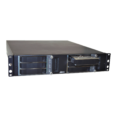
ADTX ArrayMasStor J Series User manual

ArrayMasStor
J Series
(19”Rack Model, Tower Model )
USER’S MANUAL
P/N A208233
Revision 1.2e


Advanced Technology and Systems Co., Ltd.
II
WARNING
lThe AC power cord must be connected to a grounded outlet. In case of a short-circuit,
electrical shock or fire may occur.
lDo not use the ArrayMasStor in hot, humid or dusty environments. Usage under such
conditions may result in a short circuit, electrical shock or fire.
lThe ArrayMasStor's cover must be securely attached to the chassis. If the cover is not
properly installed, ventilation could be impaired and this may cause a short circuit,
electrical shock or fire.
lDo not block the ventilation opens. Without proper ventilation, the ArrayMasStor will
malfunction or fail.
lUse the supplied AC power cord. In case of a short circuit, electrical shock or fire may
occur.
CAUTION
lRapid temperature changes may cause condensation of humidity to form on the
ArrayMasStor. Do not use the subsystem where it will not evaporate.
lDo not install the ArrayMasStor near electronic components with strong
electromagnetic fields, such as televisions or loud speakers.
lTurn off the power before moving, connecting or disconnecting the ArrayMasStor.
This will prevent vibrations or mechanical shocks from damaging the hard disk drives
(HDD) and other internal components.
lDo not remove the drive unit during normal operation, as this may cause damage,
malfunction or data loss. The drive unit should be removed when they have failed and
need to be replaced.
lUse the appropriate SCSI host card for ArrayMasStor in accordance with single-ended
or low voltage differential (LVD) SCSI interface. Using the wrong card may damage
the subsystem or cause a malfunction to occur.
lUse only the approved replacement drive unit in the ArrayMasStor. Please see
Appendix D for a list of approved replacement parts.

ArrayMasStor J Series User’s Manual
III
lDo not turn on and off in a rapid succession manner. Leave at least 15 seconds
between turning on and off. This may avoid damage or malfunction. The HDD
requires about 15 seconds to completely stop after turning off the ArrayMasStor.
lInsert to push the drive unit firmly. A loose connection may damage the
ArrayMasStor or cause it to malfunction.
lDo not turn the ArrayMasStor off by unplugging the AC power cord from the rear
panel. This may result in data loss. The ArrayMasStor’s firmware is designed to
detect the status of the power switch and synchronize the data in the cache and the
drives before shutdown. To control the power from the AC line, send a ‘synchronize
cache’1command from the host computer to the ArrayMasStor.
lWhen unplugging the AC power cord, leave one minute further before plugging it
again. This may prevent fuse damage.
IMPORTANT !
lFor optimum performance, the total length of the SCSI bus should be as short as
possible. The total cable length must be less than 1.5 mfor single-ended mode and
12m for LVD mode.
lA maximum of two host computers can be connected to the ArrayMasStor in a dual
host configuration.
lSet the ArrayMasStor’s UNIX2C/H/S mode before connecting it to the operating
systems shown below. Changing the UNIX C/H/S mode after installation may cause
data loss.
Solaris3(SPARC) 2.X
IRIX45.X
lThe backlight on the liquid crystal display (LCD) turns off automatically when the
operation buttons are not used for a period of time. The backlight will turn on when
the operation button is pressed. The backlight will stay on when a drive fails, when
the ArrayMasStor is in data reconstruction mode, and during data initialization.
1A SCSI command which ensures that logical blocks in the cache have their most recent data
value recorded in the drives.
2UNIX has two known standards, System V by AT&T and BSD4.x by Berkeley University.
3Solaris™and Spark™is a Trademark of SUN Microsystems.
4IRIX ™is a Trademark of Silicon Graphics Inc.

Advanced Technology and Systems Co., Ltd.
IV
lIt is strongly recommended that up to two ArrayMasStors be connected to the same
bus in the single-ended SCSI.
lIt is strongly recommended that the data be regularly backed up. In RAID levels 1 and
5, the ArrayMasStor will be operative when a drive fails. However, if two or more
drives fail, all of the data may not be recoverable. And, if any other parts of the
ArrayMasStor malfunction, there is possibility of data loss.
lIt is strongly recommended that the surface verification check implement before
dynamic data reallocation.
lIt is strongly recommended that an interruptible power supply (UPS) be used with the
ArrayMasStor to avoid data loss when the power line is unstable and power outrage
happens.

ArrayMasStor J Series User’s Manual
V
Table of Contents
Foreword ..……………………………………...………………………………………………………………….………I
Safety Notice ..………………………………...………………………………………………………………….………I
WARNING....………………………………...………………………………………………………………….………II
CAUTION....…………….…………………...………………………………………………………………….………II
IMPORTANT……….…………………………………………………………………………………………………..III
1INTRODUCTION TO THE ARRAYMASSTOR J SERIES............................................................1
1.1 FEATURES......................................................................................................................................1
1.2 ABOUT RAID LEVELS ....................................................................................................................2
1.2.1 RAID Level 0..........................................................................................................................2
1.2.2 RAID Level 1..........................................................................................................................3
1.2.3 RAID Level 5..........................................................................................................................4
1.3 MIXED RAID LEVELS ....................................................................................................................5
1.4 HOT SPARE FEATURE .....................................................................................................................6
1.5 WRITE BACK CACHE FUNCTION .....................................................................................................7
1.6 DYNAMIC DATA REALLOCATION....................................................................................................8
2 NAMING CONVENTION...................................................................................................................9
2.1 FRONT VIEW ..................................................................................................................................9
2.2 REAR VIEW.................................................................................................................................13
3INSTALLING THE ARRAYMASSTOR J SERIES.......................................................................15
3.1 CONNECTING THE POWER LINE CORD...........................................................................................15
3.2 CONNECTING THE SCSI CABLE ....................................................................................................15
3.3 TURNING THE POWER ON.............................................................................................................15
3.4 SETTING THE PASSWORD..............................................................................................................16
3.5 SETTING THE TIME & DATE..........................................................................................................16
3.6 SETTING THE SCSI ID..................................................................................................................16
3.7 SETTING THE SPARE MODE AND RECONFIGURING THE LUN ..........................................................16
3.8 FORMATTING...............................................................................................................................16
3.9 CONNECTION TO A MACINTOSH ...................................................................................................16
3.10 CONNECTION TO THE UNIX SYSTEMS.......................................................................................17
4ARRAYMASSTOR J SERIES OPERATIONS ..............................................................................18
4.1 OPERATION BUTTONS ..................................................................................................................18
4.2 STATUS DISPLAY (MAIN MENU)...................................................................................................19
4.2.1 Normal Mode .......................................................................................................................19
4.2.2 Degraded Mode (drive failure)..............................................................................................20
4.2.3 Drive Replacement ...............................................................................................................21
4.2.4 Data Reconstruction.............................................................................................................21
4.2.5 Data Initialization ................................................................................................................22
4.2.6 Data Reallocation.................................................................................................................22
4.2.7 Double Fault (Failure of two or more drives)........................................................................23
4.2.8 Forced Data Reconstruction.................................................................................................24
4.2.9 System Halt ..........................................................................................................................25
4.2.10 Fan Failure.......................................................................................................................26
4.2.11 Power Supply Failure........................................................................................................27
4.2.12 Surface Check...................................................................................................................28
4.3 LUN CONFIGURATION .................................................................................................................29
4.4 CHS INFORMATION......................................................................................................................29
4.5 SCSI ID INFORMATION ................................................................................................................30
4.6 DISPLAY SYSTEM CONFIGURATION...............................................................................................30

Advanced Technology and Systems Co., Ltd.
VI
4.6.1 Number of Drives.................................................................................................................30
4.6.2 Hot Spare Drive...................................................................................................................30
4.6.3 Buzzer Mode........................................................................................................................30
4.6.4 Automatic Reconstruction Mode........................................................................................... 30
4.6.5 Write Cache Mode ............................................................................................................... 31
4.6.6 AIX Error Notice Mode........................................................................................................31
4.6.7 UNIX C/H/S Mode ............................................................................................................... 31
4.6.8 Ultra SCSI Mode..................................................................................................................31
4.6.9 Initiator Mode...................................................................................................................... 31
4.6.10 Background Surface Check...............................................................................................31
4.6.11 DPO/FUA Bit...................................................................................................................32
4.7 SYSTEM STATUS.......................................................................................................................... 33
4.7.1 System Status.......................................................................................................................33
4.7.2 Serial Number...................................................................................................................... 34
4.7.3 Microcode Revision.............................................................................................................. 34
4.7.4 System Status Code ..............................................................................................................34
4.7.5 System Status Time and Date................................................................................................ 34
4.8 DRIVE STATUS............................................................................................................................35
4.9 CHANGING SYSTEM CONFIGURATION........................................................................................... 36
4.9.1 Entering the Password .........................................................................................................36
4.9.2 Changing the Date and Time Setting ....................................................................................37
4.9.3 Changing the SCSI ID.......................................................................................................... 38
4.9.4 Reconfigure .........................................................................................................................39
4.9.5 Buzzer Test .......................................................................................................................... 41
4.9.6 Changing the Buzzer Mode...................................................................................................41
4.9.7 Configuring the Write Cache Mode ......................................................................................42
4.9.8 Changing the Automatic Reconstruction Mode .....................................................................43
4.9.9 Maximum SCSI Transfer Rate ..............................................................................................44
4.9.10 DPO/FUA Bit...................................................................................................................45
4.9.11 Changing the AIX Error Notice Mode............................................................................... 46
4.9.12 Changing the UNIX C/H/S Mode ......................................................................................47
4.9.13 Performing Surface Check................................................................................................48
4.9.14 Stopping Surface Check....................................................................................................49
4.9.15 Background Surface Check...............................................................................................50
4.9.16 Setting Initiator Mode....................................................................................................... 51
4.9.17 Error Insertion.................................................................................................................52
4.9.18 Displaying the System Trace Data ....................................................................................53
4.9.19 Erasing the System Trace Data......................................................................................... 53
4.10 ADDING DRIVE UNITS..............................................................................................................54
4.10.1 Adding Unit as Hot Spare Drive........................................................................................ 55
4.10.2 Adding Unit as Data Drive...............................................................................................56
4.10.3 Adding Unit as New LUN.................................................................................................. 57
4.11 REMOVING ON-LINE DRIVES.....................................................................................................58
5TROUBLESHOOTING ..................................................................................................................59
5.1 DRIVE FAILURE...........................................................................................................................59
5.2 POWER SUPPLY MODULE FAILURE............................................................................................... 60
5.3 FAN MODULE FAILURE................................................................................................................ 61
5.4 OTHER FAILURES......................................................................................................................... 62
APPENDIX A SPECIFICATIONS.......................................................................................................63
APPENDIX B ACCESSORIES............................................................................................................65
APPENDIX C DEFAULT CONFIGURATION..................................................................................66

ArrayMasStor J Series User’s Manual
VII
APPENDIX D REPLACEMENT PARTS............................................................................................67
APPENDIX E FEATURE SETTING ...................................................................................................68
ELECTRONIC EMISSION NOTICES..................................................................................................69
FEDERAL COMMUNICATIONS COMMISSION (FCC) STATEMENT................................................................69
FCC WARNING...................................................................................................................................69
INFORMATION.....................................................................................................................................70
- MANUFACTURER..................................................................................................................................70


ArrayMasStor J Series User’s Manual
1
1Introduction to the ArrayMasStor J Series
The ArrayMasStor J Series is a compact, high performance, redundant array of independent disks.
The subsystem includes up to four hard disk drives (HDD) and offers high availability and an
excellent data transfer rate. The subsystem is easy to install and use, and has a unique interoperability
feature that allows it to work through a simple SCSI interface and be recognized as a single drive by a
host computer.
1.1 Features
The ArrayMasStor J Series
lStores a large capacity data securely with excellent performance and data availability.
lAllows afailed drive to replace without interrupting system operation. Data
reconstruction starts automatically upon drive replacement.
lData reconstruction onto the spare drive starts immediately when a drive fails. (hot spare
mode)
lImproves write performance with large-capacity cache buffer.
lRecognized as a single drive on the SCSI bus. The ‘daisy chained’SCSI connection can
be extended extremely a large storage capacity.
lComplies with the standard SCSI-3 interface.
lProvides dynamic data reallocation and background surface verification for maximum
system availability.
lAllows mixed RAID levels within the one product.

Advanced Technology and Systems Co., Ltd.
2
1.2 About RAID levels
The ArrayMasStor J Series supports three RAID levels, so you can choose the optimal level for your
application. The default setting is RAID Level 5 if at least 3 hard disk drives are online. The default
setting is RAID Level 1 if 2 hard disk drives are online. In the following examples, four drives are
assumed to be online.
IMPORTANT ! All stored data will be erased when the RAID level is
changed. Back-up the data before changing the RAID level.
1.2.1 RAID Level 0
In this level, data is striped over all of the drives in the array. This provides the maximum storage
capacity, since the entire array is used solely for data storage, and the ArrayMasStor’s input/output
performance is maximized because of the drives’parallel processing ability.
IMPORTANT ! In RAID Level 0, there is no data redundancy. Data will be
lost if a drive fails.
The effective storage capacity of this RAID level is as follows:
(Effective storage capacity) = (Capacity of one drive) x (Number of drives)
This RAID level is suitable for applications that require high performance and the largest available
storage capacity, without the need for data protection.
BLOCK 0 BLOCK 1 BLOCK 2 BLOCK 3
4 5 6 7
8 9 10 11
12 13 14 15
16 17 18 19
DRIVE 1 DRIVE 2 DRIVE 3 DRIVE 4
0
4
8
°
1
5
9
°
2
6
10
°
3
7
11
°


Advanced Technology and Systems Co., Ltd.
4
1.2.3 RAID Level 5
In RAID Level 5, parity data is generated and stored on the equivalent of one drive. If one drive fails,
the lost data can be reconstructed using data recorded on the other drives and the parity data. Parity
data is written on all of the drives in order to avoid performance degradation due to the intensive
access requirements that would result from using a single or specific parity drive.
The effective storage capacity of this RAID level is as follows:
(Effective storage capacity) = (Capacity of one drive) x (Number of drives - 1)
This RAID level is most appropriate when data protection is the primary consideration.
BLOCK 0 BLOCK 1 BLOCK 2 PARITY 0 - 2
345PARITY 3 - 5
678PARITY 6 - 8
°
°°
°°
°°
°
BLOCK 0 BLOCK 1 BLOCK 2 PARITY 0-2
4 5 PARITY 3-5 3
8PARITY 6-8 6 7
°
°
°
°
°
°
°
°
°
°
°
°
°
°
°
°
DRIVE 1 DRIVE 2 DRIVE 3 DRIVE 4
0
4
8
°
°
1
5
P
°
°
2
P
6
°
°
P
3
7
°
°

ArrayMasStor J Series User’s Manual
5
1.3 Mixed RAID Levels
The ArrayMasStor supports mixed RAID levels. This means that the ArrayMasStor can be
configured to handle multiple logical units (LU), and that a different RAID level can be assigned to
each LU. The ArrayMasStor can support up to seven separate LU (0 –6) and separate RAID levels.
A sample configuration is shown below:
LUN DESIGNATION HOST CONFIGURATION
LUN 0 - RAID 0
LUN 1 - RAID 1
LUN 2 - RAID 5
LUN 3 - RAID 0
LUN 3
LUN 2
LUN 1
LUN 0
LUN 3
LUN 2
LUN 1
LUN 0
LUN 3
LUN 2
LUN 1
LUN 0
LUN 3
LUN 2
LUN 1
LUN 0

Advanced Technology and Systems Co., Ltd.
6
PHYSICAL DRIVE 1 2 3 4
LOGICAL DRIVE 1 2 3 SPARE
1.4 Hot Spare Feature
When the hot spare feature is activated, background data recovery onto the spare drive starts
immediately after the failure of an on-line drive. This feature reduces the effective storage capacity of
the ArrayMasStor, since one drive is reserved as a hot spare. However, the hot spare feature improves
the ArrayMasStor’s reliability and its ability to protect data. After the data recovery process is
complete, the ArrayMasStor is redundant (fault tolerant) again.
In the following example, there are four drives in the ArrayMasStor. The hot spare feature is only
available when more than three drives are used.
When one of the on-line drives fails, the data recorded on the failed drive is re-generated and written
onto the spare drive. After the data recovery process is complete, the spare drive takes the place of
failed drive. For example, if drive #3 fails, the hot spare drive (physical drive #4) becomes logical
drive #3.
When the failed drive is replaced, the replacement drive becomes the spare drive.
PHYSICAL DRIVE 1 2 3 4
LOGICAL DRIVE 1 2 SPARE 3

ArrayMasStor J Series User’s Manual
7
1.5 Write Back Cache Function
When used in RAID Level 5, the write operation for small data blocks causes a data bottleneck. This
is because, before it can write the new data, the ArrayMasStor must read the old data and parity,
which are needed to generate the new parity5. This phenomenon, which is called the write penalty,
impairs performance when the host computer accesses the ArrayMasStor in a random write pattern.
The ArrayMasStor uses a large buffer as a write-back cache to compensate for the write penalty
problem. When data is acquired into the cache buffer by a ‘write’command issued by the host
computer, the ArrayMasStor returns a ‘complete’command to the host computer. The ArrayMasStor
gathers the small amounts of write data to the cache buffer and writes this data onto the drives at one
time.
When shutting down the ArrayMasStor using the power switch on the front panel, the ArrayMasStor‘s
firmware detects the power switch status, flushes the data in the cache to the drives, and then turns off
the power. When powering down from the AC line, a ‘synchronize cache’command must be sent
from the host computer to the ArrayMasStor before the power is turned off. Failure to use the
‘synchronize cache’command can result in data loss.
IMPORTANT ! Push Power Switch to turn off except for emergency. Turning
off by pulling out Power Line Cord may cause data loss in the
cache buffer.
Plugging AC power cord can’t be POWER-ON condition of ArrayMasStor J series.
IMPORTANT ! It is strongly recommended that an interruptible power
supply (UPS) be used to avoid data loss when the power
line is unstable and power outrage happens.
5This is called “Read Modify Write”.

Advanced Technology and Systems Co., Ltd.
8
1.6 Dynamic Data Reallocation
The ArrayMasStor J Series supports dynamic data reallocation, which allows the expansion of the
ArrayMasStor’s capacity by adding new drives without data loss. The additional storage capacity is
assigned a new LUN.
The original data is reallocated to suitable locations, and the parity data (for RAID Level 5) is
automatically regenerated. For RAID Level 1, the mirror data is written alongside the original data
and the original drive information is re-striped over the new drives. RAID Level 0 also offers this
feature, but there is no data redundancy when the re-stripping or reallocation procedure is executed.
Increasing the number of drives allows the same total storage capacity to be accessed faster, because
four (rather than three) drives are concurrently accessing the 40 MB of data in each LUN. Each new
LUN is treated as an individual drive by the host computer, and is easily configured from the
operating system for immediate use.
IMPORTANT ! It is strongly recommended that the surface verification
check implement before dynamic data reallocation.
IMPORTANT ! ArrayMasStor won’t permit to access from the host computer
while carrying out dynamic data reallocation.
CURRENT CONFIGURATION NEW DRIVE
NEW CONFIGURATION
LUN 0 LUN 0 LUN 0
LUN 1
LUN 0
LUN 1
LUN 0
LUN 1
LUN 0
LUN 1
LUN 0
REALLOCATION
PROCEDURE

ArrayMasStor J Series User’s Manual
9
2 Naming Convention
2.1 Front view
Front cover (rackmount type)
1. Screw for Front Cover
2. Drive Access/Status LED
3. Display Panel

Advanced Technology and Systems Co., Ltd.
10
Removal of Front cover (rackmount type)
1. Power LED
2. Host Access LED
3. Power switch
4. Drive lock
5. Drive unit #1
6. Drive unit #2
7. Drive unit #3
8. Drive unit #4
9. Drive access LED
10.Operation buttons
11.Fan Module
12.Fan module screw

ArrayMasStor J Series User’s Manual
11
Front cover (tower type)
1. Screw for Front Cover
2. Drive Access/Status LED
3. Display Panel
This manual suits for next models
20
Table of contents
Other ADTX Storage manuals
Popular Storage manuals by other brands
Transcend
Transcend TS4/8GUSDHC6-P3 Specifications
Intenso
Intenso 3823430 user manual
Garner
Garner HD-2 Series Operation and installation manual

Glyph
Glyph Companion-120 Brochure & specs
National Instruments
National Instruments HDD-8261 Getting started guide
Brainzsquare
Brainzsquare SECUDRIVE USB CAD user guide
