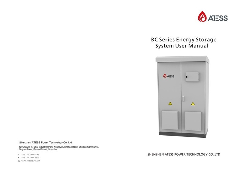
Eaton xStorage 400 User manual

p/n: P-164001032
Revision 01
400 kW Battery Energy Storage System
Installation an Operation Manual
Eaton®® xStorage 400

Eaton reserves the right to change specifications without prior notice. Samsung is a registere tra emark of Samsung Electronics Co.,
Lt . Mo bus is a registere tra emark of Schnei er Automation, Inc. MOXA is a registere tra emark an MGate is a tra emark of
MOXA, Inc. Spiralock is a registere tra emark of Spiralock Corporation. KIRK is a registere tra emark of Kirk Key Interlock company,
LLC, a subsi iary of Halma plc. National Electrical Co e an NEC are registere tra emarks of National Fire Protection Association, Inc.
ERIFLEX an FLEXIBAR are registere tra emark of Erico International Corporation. Hilti an Hilti PROFIS Engineering are registere
tra emarks of Hilti AG, Schaan. All other tra emarks are property of their respective companies.
©Copyright 2022 Eaton, Raleigh, NC, USA. All rights reserve . No part of this ocument may be repro uce in any way without the
express written approval of Eaton.
IMPORTANT SAFETY INSTRUCTIONS - SAVE THESE INSTRUCTIONS
This manual contains important instructions that you should follow during installation and maintenance
of the Battery Energy Storage System and batteries. Please read all instructions before operating the
equipment and save this manual for future reference.
To ensure you have the most up-to-date content and information for this product, please review the
latest manual revision on our website, www.eaton.com/Energy ware.

Eaton xStorage 400 Installation an Operation Manual P-164001032—Rev 01 iii
TTaabbllee ooff CCoonntteennttss
11 IInnttrroodduuccttiioonn....................................................................................................................................................................................................................................................................................................11
1.1 System Description.....................................................................................................................................1
1.1.1 Inverter System....................................................................................................................................2
1.1.2 Battery System ....................................................................................................................................2
1.1.3 Cooling and Heating ..............................................................................................................................2
1.1.4 Inverter Cooling System ......................................................................................................................... 2
1.1.5 Hydrogen Detection .............................................................................................................................3
1.1.6 Digital Dashboard .................................................................................................................................3
1.2 Using This Manual ......................................................................................................................................3
1.3 Conventions Used in This Manual .................................................................................................................. 3
1.4 Symbols, Controls, and Indicators .................................................................................................................. 4
1.5 For More Information ..................................................................................................................................4
1.6 Getting Help..............................................................................................................................................4
22 SSaaffeettyy WWaarrnniinnggss........................................................................................................................................................................................................................................................................................55
2.1 Safety Warnings.........................................................................................................................................5
33 IInnssttaallllaattiioonn PPllaann aanndd UUnnppaacckkiinngg ..........................................................................................................................................................................................................................................77
3.1 Installation Plan and Unpacking...................................................................................................................... 7
3.1.1 Creating an Installation Plan ....................................................................................................................7
3.2 Preparing the Site .......................................................................................................................................7
3.2.1 Environmental Conditions....................................................................................................................... 7
3.2.2 Installation Considerations .....................................................................................................................7
3.2.2.1 System nchoring Preparation....................................................................................................... 17
3.2.3 Power Wiring Considerations ................................................................................................................ 19
3.2.4 Interface Wiring Preparation.................................................................................................................. 20
3.3 Inspecting and Unpacking .......................................................................................................................... 21
IInnssttaallllaattiioonn .................................................................................................................................................................................................................................................................................................. 2233
4.1 Preliminary Installation Information............................................................................................................... 23
4.2 Unloading and Placement of the Eaton xStorage 400........................................................................................ 23
4.3 Battery System Installation ......................................................................................................................... 26
4.4 Two-Hole Barrel Lug Terminations to Bus Bar Installation .................................................................................. 26
4.5 External C Power Wiring Installation ........................................................................................................... 28
4.6 Installing Interface Wiring Connections ......................................................................................................... 31
4.7 Initial Startup ........................................................................................................................................... 33
4.8 Completing the Installation Checklist ............................................................................................................ 33
4.8.1 Installation Checklist............................................................................................................................ 33
55 UUnnddeerrssttaannddiinngg tthhee xxSSttoorraaggee 0000 OOppeerraattiioonn........................................................................................................................................................................................................ 3355
5.1 System Subassemblies and Component Locations .......................................................................................... 35
5.2 Eaton xStorage 400 Overview ..................................................................................................................... 37

iv Eaton xStorage 400 Installation an Operation Manual P-164001032—Rev 01
5.3 Charging Mode ........................................................................................................................................ 38
5.4 Discharging Mode .................................................................................................................................... 39
5.5 Standby Mode ......................................................................................................................................... 40
66 OOppeerraattiinngg IInnssttrruuccttiioonnss .................................................................................................................................................................................................................................................................. 11
6.1 System Controls and Indicators ................................................................................................................... 41
6.1.1 Control and Monitoring Panel ................................................................................................................ 41
6.2 Emergency Power Off (EPO)....................................................................................................................... 42
6.3 Utility Outage .......................................................................................................................................... 42
6.4 Extended Shutdown.................................................................................................................................. 42
6.5 Startup fter Extended Blackout .................................................................................................................. 42
6.6 Shutdown and Decommissioning................................................................................................................. 43
6.7 Fire Procedure ......................................................................................................................................... 43
6.8 Hydrogen Mitigation Procedure .................................................................................................................. 44
77 OOnneelliinneess aanndd SScchheemmaattiiccss.......................................................................................................................................................................................................................................................... 77
7.1 Onelines and Schematics ........................................................................................................................... 47
88 CCoommmmuunniiccaattiioonn ...................................................................................................................................................................................................................................................................................... 99
8.1 Communication........................................................................................................................................ 49
8.1.1 Communication Protocols..................................................................................................................... 51
8.2 Demand Response ................................................................................................................................... 51
8.3 Predict Pulse Dashboard ............................................................................................................................ 53
8.3.1 PredictPulse Features ......................................................................................................................... 53
8.3.2 Installing PredictPulse ......................................................................................................................... 54
8.3.3 PredictPulse Dashboard ...................................................................................................................... 54
99 MMaaiinntteennaannccee.............................................................................................................................................................................................................................................................................................. 5577
9.1 Energy Storage System Maintenance ........................................................................................................... 57
9.1.1 Important Safety Instructions ................................................................................................................ 57
9.2 Preventive Maintenance Schedule ............................................................................................................... 57
1100 PPrroodduucctt SSppeecciiffiiccaattiioonnss.............................................................................................................................................................................................................................................................. 5599
10.1 Introduction ........................................................................................................................................... 59
10.2 Models ................................................................................................................................................. 59
10.3 Input Specifications ................................................................................................................................. 59
10.4 Output Specifications .............................................................................................................................. 59
10.5 Environmental Specifications..................................................................................................................... 60
10.6 Battery Characteristics ............................................................................................................................. 60
10.7 Eaton Corporation End User License greement for the xStorage 400 ............................................................... 61
1111 WWaarrrraannttyy...................................................................................................................................................................................................................................................................................................... 7755
11.1 Warranty............................................................................................................................................... 75
1122 AAppppeennddiixx...................................................................................................................................................................................................................................................................................................... 7777
Table of Contents

Eaton xStorage 400 Installation an Operation Manual P-164001032—Rev 01 vii
LLiisstt ooff FFiigguurreess
Figure 1. Eaton xStorage 400 System ............................................................................................................. 1
Figure 2. xStorage 400 Cabinet Dimensions (Front View) ....................................................................................8
Figure 3. xStorage 400 Cabinet Dimensions (Right Side View) ............................................................................. 9
Figure 4. xStorage 400 Cabinet Dimensions (Top View) .................................................................................... 10
Figure 5. xStorage 400 Cabinet Dimensions (Bottom View) ............................................................................... 11
Figure 6. xStorage 400 Clearances — Top View .............................................................................................. 12
Figure 7. xStorage 400 Clearances — Front View ............................................................................................ 13
Figure 8. xStorage 400 Clearances — Right Side View...................................................................................... 14
Figure 9. xStorage 400 Center of Gravity —Front View ..................................................................................... 15
Figure 10. xStorage 400 Center of Gravity — Right Side View .............................................................................. 16
Figure 11. xStorage 400 Center of Gravity — Top View....................................................................................... 17
Figure 12. xStorage 400 Floor nchoring — Concrete Pad Installation.................................................................... 18
Figure 13. Conduit Box and nchor Point Locations ........................................................................................... 24
Figure 14. Forklift Opening Cover Plate Installation ............................................................................................ 25
Figure 15. Typical Bus Bar Barrel Lug Mounting – Hardware ssembly Sequence .................................................... 27
Figure 16. xStorage Dead Front Location ......................................................................................................... 28
Figure 17. C Power Terminal Locations ......................................................................................................... 29
Figure 18. C Power Terminal Detail .............................................................................................................. 30
Figure 19. Control and Monitoring Panel Installation Location — Example............................................................... 31
Figure 20. System Subassembly Locations ...................................................................................................... 35
Figure 21. Inside of Door Components and Locations......................................................................................... 36
Figure 22. Main Elements of the xStorage 400 ................................................................................................. 37
Figure 23. Path of Current Through xStorage 400 — Charging Mode ..................................................................... 38
Figure 24. Path of Current Through xStorage 400 — Discharging Mode ................................................................. 39
Figure 25. Path of Current Through xStorage 400 — Standby Mode ...................................................................... 40
Figure 26. Control and Monitoring Panel.......................................................................................................... 41
Figure 27. Eaton xStorage 400 System Oneline Schematic.................................................................................. 47
Figure 28. Eaton xStorage 400 Communication Network Diagram ........................................................................ 48
Figure 29. xStorage 400 Communication Diagram ............................................................................................. 49
Figure 30. Wireless Communications ntenna Location ..................................................................................... 50
Figure 31. PredictPulse Dashboard — t Glance Page ..................................................................................... 55
Figure 32. PredictPulse Dashboard — Fleet View .............................................................................................. 55

Eaton xStorage 400 Installation an Operation Manual P-164001032—Rev 01 ix
LLiisstt ooff TTaabblleess
Table 1. Cabinet Weights..............................................................................................................................7
Table 2. Input/Output Ratings and External Wiring Recommendations ................................................................. 19
Table 3. External Power Cable Terminations ................................................................................................... 20
Table 4. 480V Power Cable Conduit Requirements .......................................................................................... 20
Table 5. Recommended Feeder Circuit Breaker Ratings .................................................................................... 20
Table 6. Control and Monitoring Panel Interface Wiring ..................................................................................... 32
Table 7. Device Communication Protocol Detail............................................................................................... 51
Table 8. Demand Response Configurable Options ........................................................................................... 52
Table 9. Maintenance Schedule ................................................................................................................... 57

Eaton xStorage 400 Installation an Operation Manual P-164001032—Rev 01 1
CChhaapptteerr 11 IInnttrroodduuccttiioonn
11..11 SSyysstteemm DDeessccrriippttiioonn
The Eaton®xStorage 400 provides advanced energy storage capabilities used to minimize a customer’s
exposure to high demand charges from the local utility company. The xStorage 400 allows customers to reduce
operating costs through energy market participation. The xStorage 400 can draw power from the batteries as
needed to decrease the load seen by the utility at a specific time.
The xStorage 400 is protected by a weathertight cabinet. The cabinet has been tested to IP24 standards as part
of its UL listing and is designed to meet 3R requirements. Constructed primarily of aluminum, the cabinet is
designed for corrosion resistance. The external panels are fixed to the frame, and the four front doors provide
internal access for trained service personnel.
The cabinet is custom-designed to preclude contact with internal energized equipment and to prevent the entry
of dirt, rain, sleet, and snow. The all-weather cabinet design ensures the internal components are kept within
their operating temperature range.
Eyelets are provided on the roof of the cabinet for use during manufacture of the equipment. The eyelets are
not rated to lift the cabinet once it has been populated with equipment. Once populated with equipment,
the cabinet must be lifted using the forklift openings near the bottom of the cabinet.
Electrical penetrations are made in the bottom of the enclosure. Refer to paragraph
4.5 External AC Power Wiring Installation for conduit and cable entry location information.
Figure 1. Eaton xStorage 400 System

2 Eaton xStorage 400 Installation an Operation Manual P-164001032—Rev 01
11..11..11 IInnvveerrtteerr SSyysstteemm
The inverter system consists of two individual bi-directional inverters, referred to as Energy Conversion
Modules (ECMs), paralleled to each other, in order to provide the required power output to the load. The
inverters are designed to run in parallel with the incoming utility to the customer load. Under charging mode,
the inverter directs energy from the utility and charges the battery system. During high loading events, the
inverter converts DC energy from the battery to C power to supplement the utility load.
The inverter system is housed in a metal frame with its associated power electronics, separate from the
battery system.
The inverter system also contains an input/output (IO) section which acts as a landing point for external power
and control connections as well as the battery connections. This section also contains control and monitoring
hardware to connect to Eaton’s PredictPulse dashboard and provide energy service control.
11..11..22 BBaatttteerryy SSyysstteemm
Electrical energy storage is provided by the Samsung®lithium-ion battery system. The battery system is
composed of 36 battery modules installed in four battery racks. The batteries are monitored and controlled by
the Samsung Battery Management System (BMS).
11..11..33 CCoooolliinngg aanndd HHeeaattiinngg
The battery system and select portions of the inverter system are normally cooled by roof-mounted HV C
units. For select systems located in areas subject to frequent temperatures below freezing, a cold weather kit
may be installed. Heaters are integrated into the roof-mounted HV C units.
The HV C units recirculate internal air to keep the internal equipment below the maximum value permitted by
the battery compartment temperature specifications detailed in paragraph 10.5 Environmental Specifications.
The HV C cooling operation is expected during battery charging, battery discharging, and standby operation
with high ambient temperatures. The HV C units are controlled by a common thermostat and controller
installed on the inner surface of a cabinet door.
The cold weather kit includes louvers, actuators, and sensors that cool the batteries using a portion of the
airstream from the inverter cooling system (described in paragraph 1.1.4 Inverter Cooling System). When
outdoor temperatures fall below approximately -7°C (20°F), the cold weather kit will operate in lieu of the
rooftop HV C units to keep the internal equipment below the maximum value permitted by the battery
compartment temperature specifications detailed in paragraph 10.5 Environmental Specifications. Cold
weather kit cooling operation is expected during battery charging and battery discharging with low ambient
temperatures.
Heaters are integrated into the HV C units and keep the internal equipment above minimum value permitted
by the battery compartment temperature specifications detailed in paragraph
10.5 Environmental Specifications. Heater operation is expected during low ambient temperatures.
11..11.. IInnvveerrtteerr CCoooolliinngg SSyysstteemm
The inverter system is cooled by filtered, unconditioned external air. External air is pulled from the front of the
cabinet, through the filters, blowers, and inlet plenum; this filtered air is then passed through the equipment
and exhausted through another set of filters located on the roof of the cabinet. Each of the two inverter
sections is cooled by a dedicated blower.
The inlet and outlet filters are designed to maintain the weathertight performance of the cabinet. The inlet
filters also serve to preclude the introduction of dust or debris into the equipment during cooling. n air
pressure sensor is included to provide early warning of a dirty or clogged inlet filter.
System Description

Eaton xStorage 400 Installation an Operation Manual P-164001032—Rev 01 3
11..11..55 HHyyddrrooggeenn DDeetteeccttiioonn
The Samsung lithium-ion batteries installed in the xStorage 400 have been tested to UL 9540 standards to
ensure that flammable gas will not be released in the event of a battery cell thermal runaway. In the unlikely
event that battery failure that causes a battery module rupture, hydrogen gas may be released. Hydrogen gas
can ignite if allowed to build to the lower flammability limit. To preclude this, the xStorage 400 is equipped with
a hydrogen venting system that continuously monitors the cabinet atmosphere for hydrogen concentration. If
hydrogen is detected, the xStorage 400 will automatically shut down and the two dampers will open to
ventilate the enclosure.
11..11..66 DDiiggiittaall DDaasshhbbooaarrdd
The dashboard provided by Eaton PredictPulse offers 24x7 insight into the health of the xStorage 400
system. The dashboard will offer information and control for the system, including:
• System-level status, alarms, and telemetry
• bility to view and change energy service configuration parameters
11..22 UUssiinngg TThhiiss MMaannuuaall
This manual describes how to install and operate the Eaton xStorage 400. Read and understand the procedures
described in this manual to ensure trouble-free installation and operation.
The information in this manual is divided into sections and chapters. The system, options, and accessories
being installed dictate which parts of this manual should be read. t a minimum, Chapters 1 Introduction
through Chapter 4 Installation and Chapter 6 Operating Instructions should be examined.
Read through each procedure before beginning the work.
11..33 CCoonnvveennttiioonnss UUsseedd iinn TThhiiss MMaannuuaall
This manual uses these type conventions:
•Bold type highlights important concepts in discussions, key terms in procedures, and menu options, or
represents a command or option that you type or enter at a prompt.
• Italic type highlights notes and new terms where they are defined.
•Screen type represents information that appears on the screen or LCD.
Icon Description
Note Information notes call attention to important features or instructions.
[Keys] Brackets are use when referring to a specific key, such as [Enter] or [Ctrl].
In this manual, the term xStorage 400 refers only to the cabinet and its internal elements.
Using This Manual

4 Eaton xStorage 400 Installation an Operation Manual P-164001032—Rev 01
11.. SSyymmbboollss,, CCoonnttrroollss,, aanndd IInnddiiccaattoorrss
The following are examples of symbols used on the xStorage 400 or accessories to alert you to important
information:
Special Symbols
The following are examples of symbols used on the UPS or accessories to alert you to important
information:
RISK OF ELECTRIC SHOCK - Observe the warning associated with the risk of
electric shock symbol.
CAUTION: REFER TO OPERATOR'S MANUAL - Refer to your operator's manual for
additional information, such as important operating and maintenance
instructions.
This symbol indicates that you should not discard the UPS or the UPS batteries
in the trash. This product contains sealed, lead‐acid batteries and must be
disposed of properly. For more information, contact your local recycling/reuse or
hazardous waste center.
This symbol indicates that you should not discard waste electrical or electronic
equipment (WEEE) in the trash. For proper disposal, contact your local
recycling/reuse or hazardous waste center.
Eaton, Powerware, and BladeUPS are registered trademarks of Eaton Corporation or its subsidiaries and affiliates.
Phillips and Pozidriv are registered trademarks of Phillips Screw Company.
ECopyright 2008–2010 Eaton Corporation, Raleigh, NC, USA. All rights reserved. No part of this document may be
reproduced in any way without the express written approval of Eaton Corporation.
RISK OF ELECTRIC SHOCK - Observe the warning associate with the risk of electric shock symbol.
Special Symbols
The following are examples of symbols used on the UPS or accessories to alert you to important
information:
RISK OF ELECTRIC SHOCK - Observe the warning associated with the risk of
electric shock symbol.
CAUTION: REFER TO OPERATOR'S MANUAL - Refer to your operator's manual for
additional information, such as important operating and maintenance
instructions.
This symbol indicates that you should not discard the UPS or the UPS batteries
in the trash. This product contains sealed, lead‐acid batteries and must be
disposed of properly. For more information, contact your local recycling/reuse or
hazardous waste center.
This symbol indicates that you should not discard waste electrical or electronic
equipment (WEEE) in the trash. For proper disposal, contact your local
recycling/reuse or hazardous waste center.
Eaton, Powerware, and BladeUPS are registered trademarks of Eaton Corporation or its subsidiaries and affiliates.
Phillips and Pozidriv are registered trademarks of Phillips Screw Company.
ECopyright 2008–2010 Eaton Corporation, Raleigh, NC, USA. All rights reserved. No part of this document may be
reproduced in any way without the express written approval of Eaton Corporation.
CAUTION: REFER TO OPERATOR S MANUAL - Refer to your operator's manual for a itional
information, such as important operating an maintenance instructions.
Special Symbols
The following are examples of symbols used on the UPS or accessories to alert you to important
information:
RISK OF ELECTRIC SHOCK - Observe the warning associated with the risk of
electric shock symbol.
CAUTION: REFER TO OPERATOR'S MANUAL - Refer to your operator's manual for
additional information, such as important operating and maintenance
instructions.
This symbol indicates that you should not discard the UPS or the UPS batteries
in the trash. This product contains sealed, lead‐acid batteries and must be
disposed of properly. For more information, contact your local recycling/reuse or
hazardous waste center.
This symbol indicates that you should not discard waste electrical or electronic
equipment (WEEE) in the trash. For proper disposal, contact your local
recycling/reuse or hazardous waste center.
Eaton, Powerware, and BladeUPS are registered trademarks of Eaton Corporation or its subsidiaries and affiliates.
Phillips and Pozidriv are registered trademarks of Phillips Screw Company.
ECopyright 2008–2010 Eaton Corporation, Raleigh, NC, USA. All rights reserved. No part of this document may be
reproduced in any way without the express written approval of Eaton Corporation.
This symbol in icates that you shoul not iscar waste electrical or electronic equipment (WEEE) in
the trash. For proper isposal, contact your local recycling/reuse or hazar ous waste center.
11..55 FFoorr MMoorree IInnffoorrmmaattiioonn
Refer to the Eaton®xStorage 400 Service Manual for the following additional information:
• Battery system installation instructions, start-up processes, sub-assembly removal and replacement
procedures, wiring, and safety information.
• Detailed illustrations of the cabinet, connection point drawings and detailed schematics.
NOTE The Eaton xStorage 400 Service Manual is made available to customer service
engineers and authorized service technicians after completing the Eaton xStorage 400
Product Service Training.
Visit www.eaton.com/powerquality or contact an Eaton service representative for more information, see
paragraph 1.6 Getting elp.
11..66 GGeettttiinngg HHeellpp
If help is needed with any of the following:
• Scheduling initial startup
• Regional locations and telephone numbers
• technical question about any of the information in this manual
• question this manual does not answer
Please call the Customer Reliability Center at:
Unite States: 1-800-843-9433 or 1-919-870-3028
Cana a: 1-800-461-9166 ext 260
All other countries: Call your local service representative
Please use the following e-mail address for manual comments, suggestions, or to report an error in this
manual:
Symbols, Controls, an In icators

Eaton xStorage 400 Installation an Operation Manual P-164001032—Rev 01 5
CChhaapptteerr 22 SSaaffeettyy WWaarrnniinnggss
22..11 SSaaffeettyy WWaarrnniinnggss
IMPORTANT SAFETY INSTRUCTIONS - SAVE THESE INSTRUCTIONS
This manual contains important instructions that should be followed during installation and maintenance of the
Eaton xStorage 400 system. Read all instructions before operating the equipment and save this manual for
future reference.
The Eaton xStorage 400 system is designed for outdoor usage, and contains safety shields behind the door and
front panels. However, the system is a sophisticated power system and should be handled with appropriate
care.
This system contains LETH L VOLT GES. ll repairs and service should be performed by UTHORIZED
SERVICE PERSONNEL ONLY. There are NO USER SERVICE BLE P RTS inside the Eaton xStorage 400.
Doors are to be kept closed and opened by UTHORIZED SERVICE PERSONNEL ONLY.
• The xStorage 400 system is powered by its own energy source (batteries). The output terminals may carry
live voltage even when the system is disconnected from an C source.
• s a result of the connected loads high leakage current is possible. Connection to earth ground is required
for safety and proper product operation. Do not check xStorage 400 system operation by any action that
includes removal of the earth (ground) connection with loads attached.
• Ensure all power is disconnected before performing installation or service.
• ELECTRIC ENERGY H Z RD. Do not attempt to alter any battery wiring or connectors. ttempting to alter
wiring can cause injury.
• Do not open or mutilate batteries. Released electrolyte is harmful to the skin and eyes. It may be toxic.

6 Eaton xStorage 400 Installation an Operation Manual P-164001032—Rev 01
• Installation or servicing should be performed by qualified service personnel knowledgeable of battery
systems, and required precautions. Keep unauthorized personnel away from equipment. Consider all
warnings, cautions, and notes before installing or servicing equipment. DO NOT DISCONNECT the
batteries while the xStorage 400 is in service/online.
• Keep the cabinet doors closed and front panels installed to ensure proper cooling airflow and to protect
personnel from dangerous voltages inside the unit.
• Do not install or operate the system close to gas or electric heat sources.
• Operating temperatures above the recommended range will result in decreased battery life and
performance, and will reduce or void the battery warranty. Refer to Terms and Conditions of Sale with
Battery Replacement Coverage and the Battery Replacement Price Book for more information. These
documents can be found at www.eaton.com/powerquality or contact your service representative for
information on how to obtain copies.
• Observe all D NGER, C UTION, and W RNING notices affixed to the inside and outside of the
equipment.
Safety Warnings

Eaton xStorage 400 Installation an Operation Manual P-164001032—Rev 01 7
CChhaapptteerr 33 IInnssttaallllaattiioonn PPllaann aanndd UUnnppaacckkiinngg
33..11 IInnssttaallllaattiioonn PPllaann aanndd UUnnppaacckkiinngg
Use the following basic sequence of steps to install the Eaton xStorage 400:
1. Create an installation plan for the xStorage 400.
2. Prepare your site for the xStorage 400.
3. Inspect and unpack the xStorage 400.
4. Unload and install the xStorage 400, and wire the system.
5. Have authorized service personnel install the batteries.
6. Complete the Installation Checklist.
7. Have authorized service personnel perform preliminary operational checks and start up the system.
33..11..11 CCrreeaattiinngg aann IInnssttaallllaattiioonn PPllaann
Before installing the xStorage 400, read and understand how this manual applies to the system being installed.
Use the procedures and illustrations in paragraph 3.2 Preparing the Site and paragraphs
4.2 Unloading and Placement of the Eaton xStorage 400 through 4.6 Installing Interface Wiring Connections to
create a logical plan for installing the system.
33..22 PPrreeppaarriinngg tthhee SSiittee
33..22..11 EEnnvviirroonnmmeennttaall CCoonnddiittiioonnss
The xStorage 400 is intended for outdoor installations only.
Make sure that the environment for the xStorage 400 meets the following operating restrictions:
• Outdoor temperatures as specified in paragraph 10.5 Environmental Specifications.
• The xStorage 400 shall not be installed in a location where it is exposed to floodwater.
• The xStorage 400 shall not be installed in a location where it is exposed to saltwater spray or marine
environment.
33..22..22 IInnssttaallllaattiioonn CCoonnssiiddeerraattiioonnss
The xStorage 400 must be installed on a level concrete pad suitable for the weight of the system.
The xStorage 400 installation site must meet the maximum weight requirements shown in Table 1 and the size
requirements shown in Figure 2 through Figure 5. Dimensions are in millimeters (inches).
The xStorage 400 has not been tested for exposure to seismic activity.
Table 1. Cabinet Weights
Model
Weight kg (lb)
Shipping Installed
Eaton xStorage 400 2722 (6000) 4627 (10200)
NOTE Installe cabinet weight inclu es weight of installe batteries.
Table of contents
Other Eaton Storage manuals
Eaton
Eaton xStorage Compact User manual

Eaton
Eaton xStorage Home 3P User manual
Eaton
Eaton C-632X User manual

Eaton
Eaton Cutler-Hammer SRAM PC104 User manual
Eaton
Eaton xStorage Compact 20 kW User manual

Eaton
Eaton xStorage Home 3P User manual
Eaton
Eaton xStorage Home 3P User manual

Eaton
Eaton RE Series User manual

Eaton
Eaton Cutler Hammer SRAM PC104 User manual

Eaton
Eaton xStorage Home 3P User manual


