© MDM INCORPORATED
WWW.MDMINC.COM
Corrosion-resistant, non-metallic pumps.
PROUDLY MADE
IN THE USA
4000
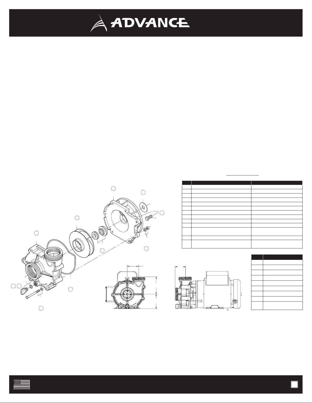
VOLUTE
IMPELLER
WASHER &
LOCK NUT
BRACKET
MBOL
LARGE
O-RING
SEAL
P-BOLT
& WASHER
N PLUG
& O-RING
SLINGER
12
3
4
5
6
8
9
9
PUMP END ASSEMBLY
1. Electrically connect the motor so that the impeller will rotate counterclockwise when facing the pump with the motor toward the rear. Warning: Incorrect
rotation will damage the pump and void the warranty. For 3 Phase Power: Electrically check rotation of impeller with volute disassembled from bracket If
pump end is assembled and rotation is incorrect, serious damage to pump end assembly can occur even if the switch is “quickly bumped.” If rotation is
incorrect, simply exchange any two leads.
2. Clean and inspect all pump parts (0-ring, seal seats, motor shaft, etc.).
3. Apply sealant to the bracket bore ID wall and around the seal case - follow sealant mfg. instructions. We recommend using Gasgacinch®, Permatex® or 3M®
1300L. Silicone sealant can also be used for seals with metallic casings (not for Impenatra®seal).
4. Press seal head into bracket using a tool that is 1.5’’ (38mm) in width that will apply pressure to the seal case shoulder. Warning: Do not apply pressure to the
carbon or silicon carbide seal head.
5. Step A: Place slinger (rubber washer) over motor shaft. Step B: Mount bracket to motor using four M bolts supplied using a 9/16” (15mm) ratchet wrench.
Step C: Tighten bolts in a cross pattern to 60 in-lbs.
6. Step A: Carefully, lubricate the seal seat elastomer OD and impeller hub ID with water. Step B: Press the seal seat into the impeller hub making certain that
the ceramic is in evenly - the sealing surface should be parallel with the impeller hub.
7. Carefully lubricate carbon-graphite and ceramic sealing surfaces with clean water. Warning: Do not use silicon lubricants or grease.
8. Step A: Thread impeller onto shaft and tighten! If required, remove motor end-cap and use a screwdriver on the back of motor shaft to prevent shaft rotation
while tightening. Step B: Replace motor end cap.
9. Step A: Seat large O-ring in volute O-ring channel. Step B: Assemble volute to bracket with the 1/4-20 x 2 ¾” hex cap screws, washers and nuts using two (x2)
7/16” (12mm) ratchet wrenches. Step C: Tighten in a cross pattern (60 in-lbs).
10. Install drain plug with its O-ring in volute drain hole.
11. Before operating pump, allow a proper cure time for the sealant used in step 3.
DISASSEMBLY
1. Step A: Shut off power to motor before disconnecting any electrical wiring from the back of the motor. Step B: Remove drain plug to drain or empty out pump
2. Disassemble volute from bracket by removing the seven 1/4” - 20 x 2 3/4” hex cap screws with a 7/16” (12mm) wrench.
3. Remove cap covering shaft at back of motor and with a large screwdriver. Warning: Prevent shaft rotation while unscrewing impeller.
4. Remove ceramic piece from impeller with either a flat head screw driver or pliers. Warning: Eye protection is recommended when replacing the seal.
5. Detach bracket from motor using a 9/16” (15mm) wrench.
6. Remove mechanical seal from bracket by pressing out from the back. Warning: If you are replacing the seal, do not dig out from the front.
QTY TOOLS / MATERIALS USAGE
1 9/16” (15mm) WRENCH TIGHTEN BRACKET BOLTS
2 7/16” (12mm) WRENCH TIGHTEN VOLUTE BOLTS
2 1/2” (13mm) WRENCH ** FOR 3000’S TIGHTEN BOLTS
1 FLATHEAD SCREWDRIVER HOLD SHAFT IN PLACE
1 PLIERS HOLD SHAFT IN PLACE
1 ROLL OF PAPER TOWELS CLEAN HANDS AND PARTS
1 BOX OF LINT FREE TISSUE CLEAN SEAL FACE SURFACES
1 CAN / TUBE GASGACINCH®, SILICONE SEALANT FOR SEAL INSTALLATION
1 BOTTLE OF LUBRICANT, P-80, 3N1 OIL FOR SEAT INSTALLATION
1 BOTTLE OF RUBBING ALCOHOL CLEAN SEAL FACE SURFACES
1 ARBOR PRESS 1. TO PRESS SEAL INTO BRACKET
2. PRESS SEAT INTO IMPELLER
1 **HAMMER/ MALLET **IF ARBOR PRESS IS NOT AVAILABLE
1 CHAMFERING TOOL 1. CHAMFER IMPELLER BORE EDGE
2. CHAMFER BRACKET BORE EDGE
P.3
NO. DESCRIPTION
1 DRAIN PLUG
2 O-RING (DRAIN PLUG)
3 VOLUTE
4 LARGE O-RING
5 IMPELLER
6 MECHANICAL SEAL
7 BRACKET
8 SLINGER
9 (7) P-BOLT, (7) PUMP NUT,
(14) WASHER, (4) *M-BOLT
Pump end and motor illustrations are for reference only.
2.75” 2.43”
3.50”
4.22”
TOOLS & MATERIALS