ADVANCE Easy Moving FIREPOD universal Quick setup guide

SYSTEM
FIRE POD UNIVERSAL
ASSEMBLY, USE AND
MAINTENANCE MANUAL
26


20/10/21 Rev:1.0.1 (LINGUA ORIGINALE)
3
• Type: Supply system for solid fuel fireplaces
• Model: FIREPOD universal
• Revision 1.0.1
System
FIREPOD universal
INSTRUCTION MANUAL
1 INTRODUCTION 4
1.1 Using the manual 4
2 WARNINGS 4
3 PRODUCT DIMENSIONS AND TECHNICAL DATA 5
3.1 Identification plate 6
3.2 Safety symbols 6
4 KIT AND ACCESSORIES 7
5 INSTALLER’S RESPONSIBILITIES 8
6 INTENDED USE OF THE SYSTEM 8
6.1 Installation diagram 8-9
7 INSTALLATION of the basic components 10
7.1 Control panel 10
7.2 dispenser tank 10
7.3
Installation of the dispenser on tanks and compartments with controlled pressure
11
7.4 Motor 11
7.5 Suction inlet 12
7.6 Antistatic flexible piping Ø 45 mm 12
7.7 Flexible pipe with suction lance 13
7.8 electrical connection cables 14
8 ACCESSORIES - OPTIONAL 14
8.1 Minimum level sensor for tank 14
8.2 Air exhaust silencer 15
8.3 Dust separator filters 15
8.4 Antistatic PU flexible pipe Ø 45 mm 15
8.5 Sleeve Ø 45 mm for joints 15
8.6 Adjustable shelf for rectangular dispenser tank 16
8.7 Electrical wiring extensions 16
9 PIPES CONNECTIONS 16
10 ELECTRICAL WIRING 17
11 SUMMARY OF THE INSTALLATION PHASES 17
12 FIRST START-UP AND COMMISSIONING 17
13 CORRECT USE OF THE SYSTEM 18
14 MAINTENANCE AND END OF LIFE 19
14.1 End of life 19
15 TROUBLESHOOTING 20
16 WARRANTY 21
17 CERTIFICATION 22
INDEX

Universal system instruction manual
125/10/21 Rev:1.0.1
4
1 INTRODUCTION
Dear Customer,
We would like to thank you for choosing to purchase an our product, the technical characteristics of
which are certain to satisfy your needs.
Our products have been designed and built according to current regulations, having chosen the best
materials in order to obtain a user friendly and highly durable product.
We therefore ask you to read this manual carefully, completely and to meticulously follow the instructions
contained herein.
1.1 Using the manual
This manual is a document prepared by the manufacturer and is an integral part of the product: it
combines the norms of the sector of application and the general rules concerning the safety of people,
objects and animals.
In the event that the product is resold, given, rented or passed over to others, it must always be
accompanied by this manual; it is therefore recommended to use it and keep it carefully for the entire
operating life of the product.
The main objective of this manual is to familiarise the product and its correct, safe use.
Nopartofthismanualmaybereproducedorcopiedwithoutthewrittenauthorisationofthemanufacturer.
The manufacturer reserves the right to make improvements and modifications to this manual and to the
product itself without having the obligation to notify third parties in advance.
2 WARNINGS
• Do not use the product improperly.
• Do not let children near the product.
• This appliance must not be used by people (including children) with reduced psychological, sensory
or mental abilities, or by inexperienced/uninformed people, unless they are supervised or instructed to
use the appliance by people responsible for their safety.
• Use only original spare parts.
• Do not allow any parts of the body to make contact with the equipment before disconnecting the power
supply
• Disconnect the power supply when an extended period of inactivity is expected.
The Manufacturer declines any form of liability or guarantee if the buyer or their agent make any
changes, or even minor adjustments to the product as puchased.
5
English
20/10/21 Rev:1.0.1
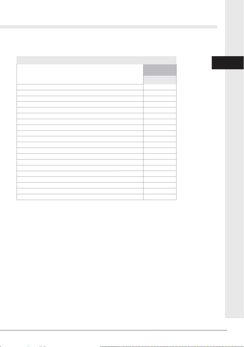
3 PRODUCT DIMENSIONS AND TECHNICAL DATA
Firepod
Model
Item
FIRE POD
AP3400.00.20
Attachments Ø mm 45
Electric motor protection level IP 20
Level of electrical protection control panel
IP 40
Level of electrical protection suction inlet
IP 40
Operating temperature min/max °C 0 ÷ 50
Min/max humidity level % 30 ÷ 95
Supply V ac 230
Frequency Hz 50
Motor power kW 1,35
Absorption A 5,8
Thermal circuit breaker A 8
Max dosing capacity l 6
dispenser tank weight kg 2,2
Control panel weight kg 0,45
Motor weight kg 1,8
Motor plate weight kg 0,55
Weight of complete suction inlet kg 0,15
Weight of antistatic hose kg/m 0,35
Weight of connection cables kg/m 0,15
Noise dB(A) < 70
N. B: Nominal noise values. The values may vary according to the environment in
which the product is installed and the type of installation

Universal system instruction manual
125/10/21 Rev:1.0.1
6
3.1 Identification plate
The CE identification plate is present on each component of the system Universal.
Do not remove or damage the nameplate.
....................................
.........................................................................
Model:
P/N: S/N:
System type Identification of the manufacturer
CE conformity
marking
Electric motor technical data
Serial number
Article number
We remind you to pay maximum attention to pictograms and danger/prohibition warnings
found on various parts of the product: if not observed, it is possible to encounter unsafe
situations.
DANGER FROM VOLTAGE OR ELECTRIC CURRENT
Danger of serious personal injury.
During maintenance operations, disconnect the electricity and make sure that the
power supply cannot be restored.
CUTTING HAZARD
Danger of serious personal injury.
During maintenance operations, disconnect the electricity and ensure that the
power supply cannot be restored.
AUTOMATIC STARTING HAZARD
Danger of serious personal injury.
During maintenance operations, disconnect the electricity and ensure that the
power supply cannot be restored.
DANGER TO THE HAND FROM THE AUGER IN OPERATION
Danger of serious personal injury.
During maintenance operations, disconnect the electricity and ensure that the
power supply cannot be restored.
3.2 Safety symbols
ADVANCE
EasyMoving
MIN
MAX
+
7
English
20/10/21 Rev:1.0.1
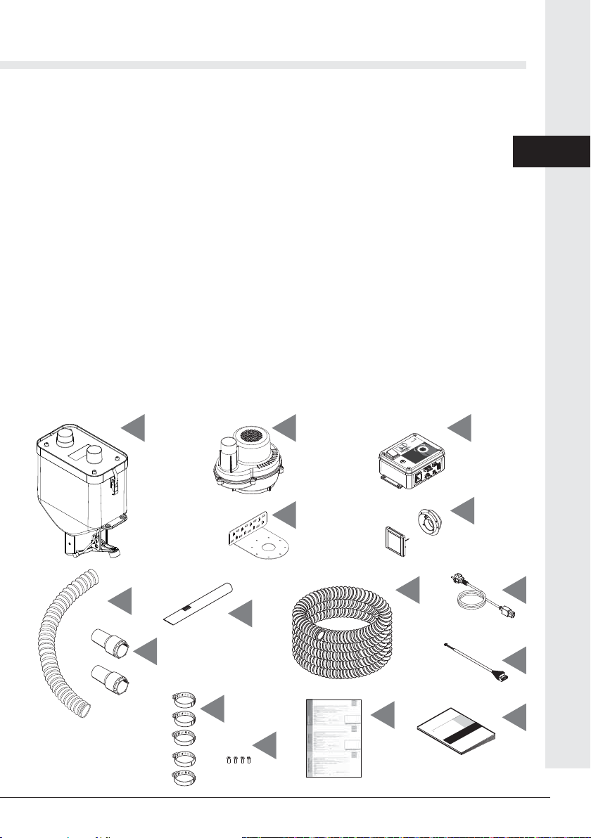
4 KIT AND ACCESSORIES
The system sales package includes:
1) 1 x rectangular dispenser tank
2) 1 x motor
3) 1 x motor fixing plate
4) 1 x control panel
5) 1 x complete suction inlet
6) 1 x flexible pipe 1,5 meters
7) 2 x fittings for flexible pipe
8) 1 x metal lance
9) 1 skein 6 meters antistatic flexible P.U.
10) 1 x cable for control panel power supply
11) 1 x cable for suction inlet-control panel connection
12) 5 x metal hose clamps
13) 4 x TCC5x12SP screws for fixing the motor / plate
14) 1 x guarantee form
15) 1 x assembly, use and maintenance manual
Check that the control unit, its accessories and the kit correspond to what was ordered and that they
do not show obvious signs of transport damage.
If this is not the case, notify the Dealer immediately.
12
13
15
MANUALE TECNICO
ADVANCE
EasyMoving
MIN
MAX
+
1 2 4
9 10
11
5
3
6
7
8
14

Universal system instruction manual
125/10/21 Rev:1.0.1
8
5 INSTALLER’S RESPONSIBILITIES
To ensure proper operation of the product, follow these guidelines:
• Only perform the activities described in these instructions
• Perform all activities in accordance with applicable regulations
• Explain to the user the operation and use of the product
• Explain to the user how to maintain the product
• Report to the user the potential dangers related to the use of the product
6 INTENDED USE OF THE SYSTEM
The system is a system that fills the fuel tanks of pellet operated fireplaces, thermo-fireplaces, inserts,
stoves, etc.
It can also transport other granular fuels, obtained from biomass such as pomace, corn, shredded dried
fruit shells, etc.
The system achieves maximum performance when used for EN-plus A1 certified pellets.
Thesystem sucks the pellets directly from rigid containers orbags, using the lance supplied and deposits
it in the stove tank automatically. It stops by itself when the fuel inside the tank prevents the discharge
door from closing. doser (see point 6.2).
Its components can also be installed inside the furnishings that integrate inserts and fireplaces
aesthetically, provided they remain accessible for maintenance purposes.
The system cannot vacuum products with too fine (<2mm) or too large (> 10mm) granulometry, or
excessively dusty, damp and liquid (flour, household dust, sawdust, unshredded shells, liquids, etc.)
It is useful to know that any object which is sucked in could inevitably be released into the chimney tank
with the associated consequences.
All the components, pipes and accessories of the system cannot be installed in extremely humid/ dusty
environments or positions, those exposed to bad weather, where dripping or flooding can occur, where
temperatures below 0° c or above 50° c may occur.
6.1 INSTALLATION DIAGRAM
Key:
1 - Fuel suction lance
2 - Suction inlet with backplate for wall fixing
3 - Fuel suction antistatic pipe Ø 45 mm
4 - Doispenser
5 - Air / dust suction antistatic flexible hose Ø 45 mm
6 - Motor
7 - Control panel
8 - Air / dust discharge antistatic flexible hose Ø 45 mm
9 - Burner

9
English
20/10/21 Rev:1.0.1
1
2
34
56
7
8
9
IN OUT
OUT
IN
Universal system instruction manual
125/10/21 Rev:1.0.1
10
7 INSTALLATION OF THE BASIC COMPONENTS
Before commencing installation of the system, it is useful to know that some of its components require
particular precautions regarding their positioning, in particular the control panel. It is essential that it is
easily visible by the system user, to facilitate ignition and adjustment procedures.
The air filter (optional) must also be accessible to facilitate cleaning. The motor must be installed in a
position where the surrounding air temperature does not exceed 50 ° c.
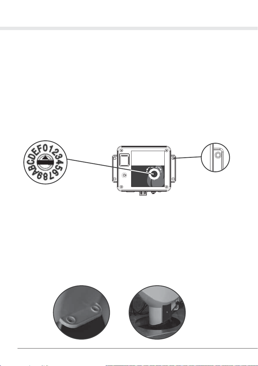
7.1 Control panel
The control panel contains all the controls and adjustments of the system. It must therefore be installed in
an easily accessible position to proceed with the on / off and adjustment operations.
The adjustment of the suction cycle times takes place via the 16-position switch located on the front, which
varies the cycles from 2 to 32 seconds (see figure 1)
The panel must be permanently fixed by its anchor points (see figure 2), away from sources of excessive
heat and protected from water.
Figure 1 Figure 2
0
1
7.2 Dispenser tank
The dispenser tank must be permanently fixed by its anchor points (see figure 3), above the fuel tank,
taking care that it is perfectly level. Alternatively the multiposition shelf (optional) can be used.
Where possible, the dispenser tank should be installed in a position that does not obstruct any neces-
sary manual filling of the tank.
To facilitate the complete filling of the tank, it is advisable that the lower discharge door of the dispenser
tank is positioned at the same level as the mouth of the tank but never higher than this (see figure 4).
It is equally possible to install the dispenser tank with the lower discharge door positioned inside the
tank itself.
However, it is essential that the dispenser tank unit discharge door is positioned in such a way that when
the tank is full of fuel it cannot close by itself.
This way you can ensure that the filling of the tank stops automatically.
Figure 3 Figure 4

11
English
20/10/21 Rev:1.0.1
Before proceeding with the final fixing of the dispenser tank, make sure that it is easy to open its
upper cover by means of the two hooks, to facilitate access to its interior for any maintenance.
Also check that the lower discharge door of the dispenser tank can be completely opened and closed
without impact on the tank walls.
7.3 Installation of the dispenser on tanks and compartments with controlled pressure
It is important to remember that pneumatic conveying systems work by modifying the state of
pressures present in the various components of the system itself: in this case, during the operation
of our systems, inside the dispenser there can be a pressure varying between about -0,080 to -0,24
bar (-1,16 to -3,48 psi).
Particularly during the operating phases of the plant, due to the features of the dispenser, a slight
extraction of air from the fuel discharge point may take place.
These suctions, due to small particles of dust that prevent the perfect sealing between the discharge
outlet and the rubber plate, do not compromise the proper functioning of the transport system, instead
they could change the internal pressure of the tank or that of the compartment where the chimney is
installed, compromising its safety.
It is possible to solve this problem mainly by programming the working time of the fuel transfer system
only when:
A) The brazier of the boiler is switched off and cold
B) The loading door of the tank is open and there is an air inlet between the closing compartment of
the chimney and the outside;
C)The communication channel between the fuel tank and the boiler brazier is completely closed;
D) the exhaust fan of the chimney works at maximum power;
E) On the boiler tank is present an electrical valve, with proper dimensions, connected to the fuel
feeding transport system, which allows an easy compensation of the air sucked.
7.4 Motor
The motor must be installed using the supplied mounting plate (see figure 5), it must be fixed to a
robust support, in an accessible position for any maintenance, away from sources of excessive heat
and protected from water.
The ventilation grilles, visible on its casing, must always remain completely free from dust and / or
foreign objects (see figure 6)
Figure 6
Figure 5

Universal system instruction manual
125/10/21 Rev:1.0.1
12
7.5 Suction inlet
The suction inlet is designed to be positioned on a masonry or plasterboard wall and is composed of:
- the mounting plate, to be applied in the masonry or to be fixed firmly on the back of the plasterboard
wall (see figure 7).
- the inlet with flap, which after the wall remedial work must be screwed to the mounting plate and will
remain visible (see figure 8).
The flexible hose with lance must be connected to the suction inlet every time the fuel suction operation
is performed.
This inlet must be installed firmly.
It is recommended to place it in an area near the fireplace. For ergonomic comfort it is recommended to
place it at a height between 40 and 70 cm from the ground.
In the suction inlet there is a red LED to signal low fuel level in the tank. The LED is only operational if a
minimum level sensor is installed in the fireplace tank (optional).
7.6 Antistatic flexible piping Ø 45 mm
The pipe supplied with the system is flexible (see figure 24), made of thick polyurethane and is equipped
with a copper strand. It should be cut to size, to connect the various components of the system.
The maximum recommended lengths for connecting the various system components are as
follows:
- 2.5 meters from the suction inlet to the dispenser tank (max 3.30 m)
- 2 meters from the doser to the motor (max 3 m)
- 1.5 meters from the motor to the air discharge point (max 2.30 m)
To obtain the maximum efficiency of the system, it is however advisable that the sum of the
lengths of the pipes does not exceed 9 meters, and in particular that the length of the fuel pipe
between the suction inlet and the dispenser tank must be as short as possible.
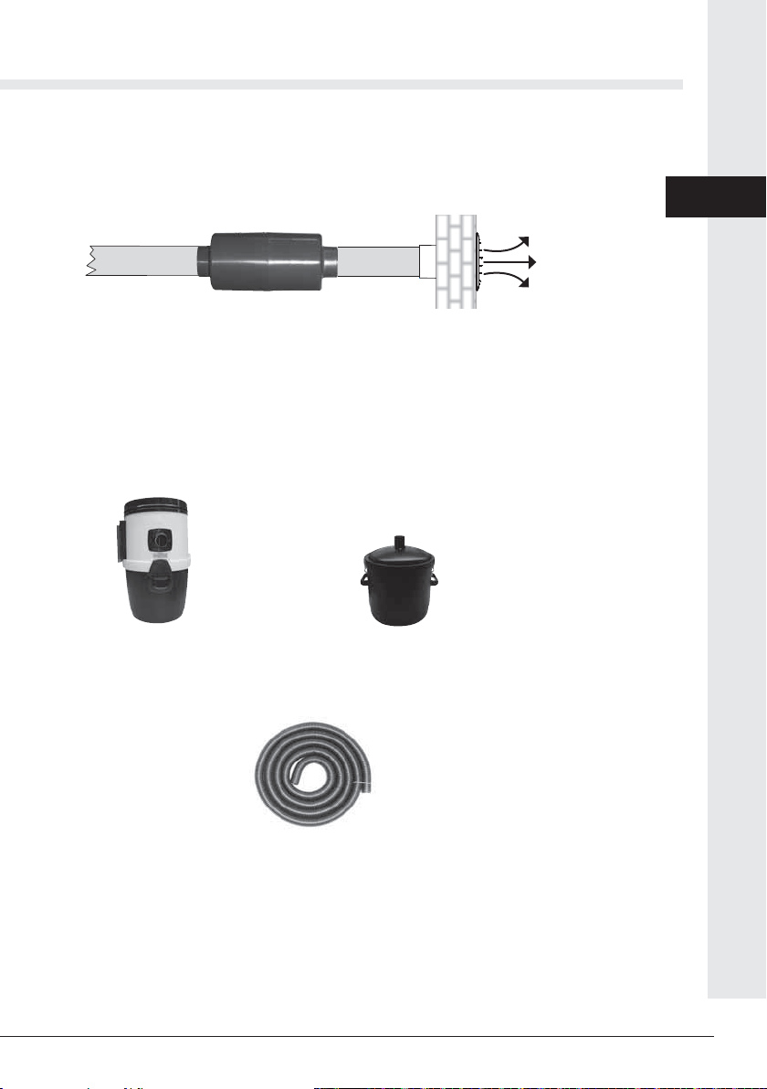
Air can be discharged directly to the outside, with or without the use of the silencer (optional see figure
9), or internally by connecting to a dust filter (optional see figure 10)
In the event of external expulsion, the section of air discharge pipe can be a maximum length of 5 me-
ters, but only when using pipes of ø 50 mm or more.
All sections of the pipe must be connected to the components and fixed using the hose clamps supplied
for maximum air tightness.
Figure 9 Figure 10
Figure 8 Figure 7
Figure 24

13
English
20/10/21 Rev:1.0.1
Using the copper filament inside it, each section of pipe must be connected to an grounding
point of the electrical system, to ensure the dispersion of static charges (see figure 11).
7.7 Flexible pipe with suction lance
This 1.5 meter pipe must be assembled by screwing in the rubber fitting that will support the
steel lance to one end (see figure 12)
on the other end, screwing in the fitting that will be used for the connection in the suction inlet
(see figure 13).
The hose will only be connected to the suction socket before each loading operation and dis-
connected once completed (see figure 14).
Figure 13
Figure 14
Figure 12
Figure 11
Universal system instruction manual
125/10/21 Rev:1.0.1
14
8 ACCESSORIES - OPTIONAL
8.1 Minimum level sensor for tank
The minimum level of the tank can be monitored by a sensor equipped with a cable for connection to the
control panel.
By installing the sensor in the appropriate position inside the tank (see figure 19)
and connecting it to the control panel, the LED function on the suction inlet will automatically be activated
(see figure 20), the red LED lights up to indicate that the minimum fuel level in the tank has been reached.
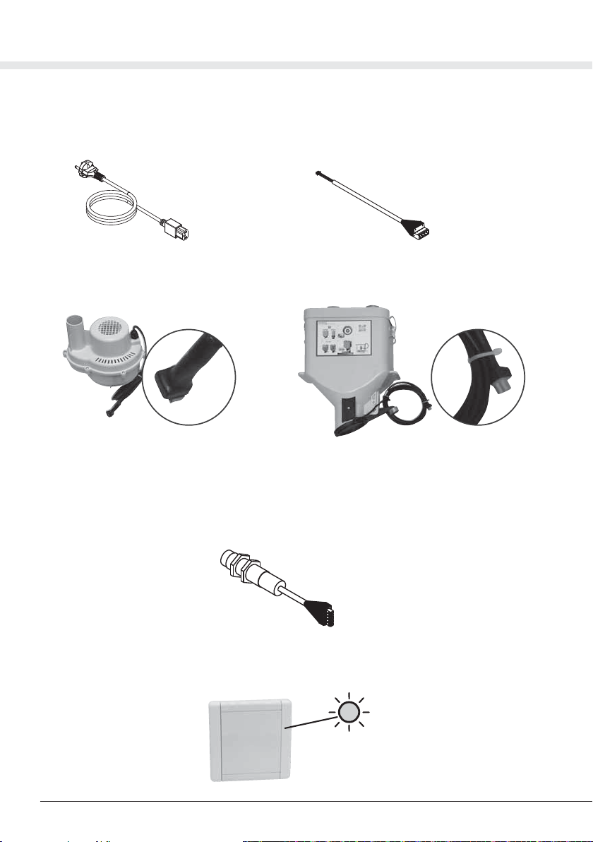
7.8 Electrical connection cables
The electric cables supplied are all equipped with different wiring to avoid positioning errors. The cables
allow the connection of power supply to the control panel (see figure 15) and the connection of the suc-
tion inlet to the control panel (see figure 16 ).
The other components of the system are already equipped with a cable with relevant wiring to be con-
nected to the control panel using the corresponding socket (see figure 17 - 18).
Figure 17 Figure 18
Figure 19
Figure 20
figure 15 figure 16
15
English
20/10/21 Rev:1.0.1
8.2 Air exhaust silencer
The silencer has the task of damping the noise caused by the expulsion of air. If it is conveyed
as it is towards the outside, it must be connected to the end of the air discharge pipe just before
the expulsion outlet (see figure 21)
8.3 Dust separator filters
The dust filters have the task of filtering dust filled air expelled during the operating phases of
the system.
The expelled air will therefore be clean and free of dust particles, making this accessory suitable
for releasing air in an indoor environment.
A filter has a fixed wall mounting (see figure 22) and another smaller, lighter model with handles
and feet, (see figure 23) can be positioned more easily on the ground or on a shelf, also just
during loading operations.
8.4 Antistatic PU flexible hose Ø 45 mm
The 6 m length hose (see figure 24)
it can be useful if the distances to be covered between the various components of the system
are greater than the standard. However the length limits allowed for the various sections
must always be respected (see point 6.5).
8.5 Sleeve Ø 45 mm for joints
This rubber sleeve with steel shell is used to make joints of the antistatic flexible piping ø 45 mm
and includes 1 rubber sleeve, 1 steel band with clamping screws, 1 electrostatic continuity plate.
Figure 22
Figure 24
Figure 23
Figure 21

Universal system instruction manual
125/10/21 Rev:1.0.1
16
For the component connections, the system includes a skein of antistatic polyurethane hose, equipped
with a rib and a grounding copper cord.
The different hose sections are shown in the diagram in paragraph 6.1 of this manual, and are:
-a section from the vacuum socket to the IN connector of the dosing unit
-a section from the OUT connector of the dosing unit to the IN connector of the motor
-a section from the OUT connector of the motor to the dust filter or to the outside
Maximum lengths and tolerances allowed for hoses:
-vacuum socket - dosing unit section m 2.5 + max 30%
-dosing unit - motor section m 2 + max 50%
-motor - air exhaust section m 1.5 + max 50%
To maximise system efficiency, however, the total length of the hoses should never exceed 9 metres;
the length of the hose conveying the fuel from the vacuum socket to the dosing unit, in particular, should
never exceed 3.6 m.
It is important that all hose connection points are fastened with steel hose clamps, and that there are no
cracks or air leaks. Any junctions must be made using the specially designed rubber sleeves (optional).
The different hose sections must be firmly fastened to a wall or to a stable surface, and must have no
dips or excessive bends. Any bends must have a minimum radius of 50 cm.
Keep the hoses away from heat sources like funnels, combustion chambers, air/flue heat
exchangers.
All hose sections must be connected to an electrical system grounding point, through the
copper filament they contain.
9 PIPES CONNECTIONS
8.6 Adjustable shelf for rectangular dispenser tank
The pair of shelves is suitable for easy dispenser tank mounting above the tank loading mouth, allowing
a series of adjustments that permit the dispenser tank to be positioned level and correctly (see figure 25)
8.7 Electrical wiring extensions
The extension cables are supplied with the relevant connectors to extend the wiring from the motor to the
control panel (3 m) from the metering unit to the control panel (3 m) and from the minimum level sensor
(optional) to the control panel ( 4 m).
Figure 25
Max 168 mm
Min 103 mm
Max 86 mm

17
English
20/10/21 Rev:1.0.1
The control panel is equipped with a cable which guarantees the power supply to the entire
system. In the control panel there are also connectors for the other components of the system
to be made using the cables supplied. To avoid incorrect connections, each cable has a
unique connector (see figure 26).
10 ELECTRICAL WIRING
a) mount the components in suitable positions (see point 6)
b) connect the components with the pipes supplied (see point 7)
c) connect the components with the electrical cables supplied (see point 8)
d) connect the pipes to an electrical system grounding point
e) proceed to point 11 for the first start up
Check that the operations listed in the previous points have been carried out correctly.
Before connecting to the electrical network, check that the voltage supply corresponds to the
required voltage and that the electrical system is built in compliance with current regulations.
Connect the control panel power supply cable to a power outlet, set the 0-1 switch on the control
panel to 1 and check that the switch lights up, open the suction inlet flap and insert the flexible pipe
equipped with lance.
The system will now start operating with 2-second suction cycles and short, consecutive, repetitive
shutdowns (the shutdown phases allow the fuel to be discharged from the metering unit into the
tank).
After a few empty cycles you can start sucking the fuel by placing the lance on the fuel. At this point
in each suction cycle a small amount of fuel will be transported to the doser which in turn will fall
into the tank.
The optimum suction cycle time is that which allows enough fuel to flow up to the doser, occupying
about half of its volume (optimal times vary between 10 and 16 seconds on average)
11 SUMMARY OF THE INSTALLATION PHASES
12 FIRST START-UP AND COMMISSIONING
Then connect the cables to the respective control panel connectors, avoiding their passage near
sources of excessive heat such as chimneys, combustion chambers, exchangers, etc. Then
mount the cables on fixed supports to avoid unwanted movement.
Figure 26
Power supply
230 V Minimum tank level
sensor (optional)
Suction inlet
Motor
dispenser tank
Minimum tank level reached signal (optional)
normally open contact

Universal system instruction manual
125/10/21 Rev:1.0.1
18
When you want to fill the tank, proceed as follows:
a) set the illuminated switch on the control panel to 1 and check that the switch lights up
b) open the suction inlet flap and insert the flexible hose equipped with a lance
c) c)when the system starts the suction cycles, position the lance in the bag or in any other
container of the fuel to be aspirated. The suction lance must never be completely immersed
in the fuel to be sucked, the fluidization grille placed in the front of the lance must always be
left free to suck air (see figure 27)
d) topping up can be interrupted at any time simply by lifting the lance from the fuel and
extracting the flexible pipe from the suction inlet. Regardless, when the tank is full, the
suction cycles are interrupted automatically.
e) at the end of the operation, disconnect the flexible pipe from the suction inlet and make sure
that the inlet flap is properly closed. In this way the system stops functioning.
f) if you do not intend to use the system for a long period, set the illuminated switch on the
control panel back to 0.
13 CORRECT USE OF THE SYSTEM
Figure 27
Now check that the duration of each suction cycle is long enough to fill the dispenser tank with the right
amount of fuel, at least up to half of its internal volume.
To make this check at the end of a suction cycle, keep the outlet door closed after completing a cycle
and turn off the system, then open the lid of the dispenser tank and check the contents.
Now use the trimmer located in the center of the control panel to change the time of the suction
cycles, at each click the time of the suction cycle changes by 2 seconds. Turning it clockwise with a
small screwdriver will lengthen the time and bring more fuel in the metering unit, vice versa, turning it
anticlockwise with each click, the time will shorten by 2 seconds and less fuel will be brought into the
metering unit.
There are 16 trimmer positions and they regulate the time of the suction cycles from 2 to 32 seconds.
The 0 seconds position is not present.
To completely fill the tank, continue holding the lance on the bulk fuel, until the operating cycles stop
automatically on their own.
The operating cycles cease when there is such a quantity of fuel in the tank that the lower door of the
dispenser tank is not closed.
At the end of the operation, always disconnect the flexible hose from the wall inlet and make sure that
the inlet flap closes properly.

19
English
20/10/21 Rev:1.0.1
Good maintenance of your system will guarantee a long operating life and reduce its electricity
consumption.
Always keep the dust filter bag clean where installed, replacing it when full.
Clean the lower fuel discharge flap of the metering device if dust or deposits settle on it. (see
figure 28)
14 MAINTENANCE AND END OF LIFE
Figure 28
Clean the mesh filter installed inside the dispenser tank, which can be reached by opening the
lid using the two hooks positioned on both sides. (see figure 29)
Blow the motor ventilation grids annually with low pressure compressed air to eliminate any
dust deposits.
To ensure the optimum and long-lasting operation of the system, in the event of breakdowns,
it is recommended to contact an authorized service center and to use only original spare parts.
14.1 End of life
The disposal of the packaging, accessories and the out-used system must be carried out according
to the regulations in force locally, ensuring the recycling of the raw materials of which they are
composed.
Figure 29
Universal system instruction manual
125/10/21 Rev:1.0.1
20
The suction force is reduced or zero
- there is a blockage of material in the lance holder hose or in the connection pipe between the
suction inlet and the dispenser tank
- there is a split, a hole, a cut, or an air leak, in the lance holder hose, or in the connection pipe
between the suction inlet and the doser, or in the connection pipe between the doser and the
motor
- the air outlet is blocked
- the air filter (if installed) is blocked
- the lower dispenser tank discharge flap has remained slightly open
- the dispenser tank top lid is not closed correctly
- the mesh filter inside the dispenser tank is clogged
The system works even if the lance holder hose is not inserted in the suction socket
- the door of the suction socket is not perfectly closed
- the micro switch of the suction inlet does not work
Suction does not work
- the lower dispenser tank discharge flap is open
- the micro switch of the doser does not work
- the switch light 0-1 is off and therefore there is no power supply to the system
- the thermal circuit breaker has tripped
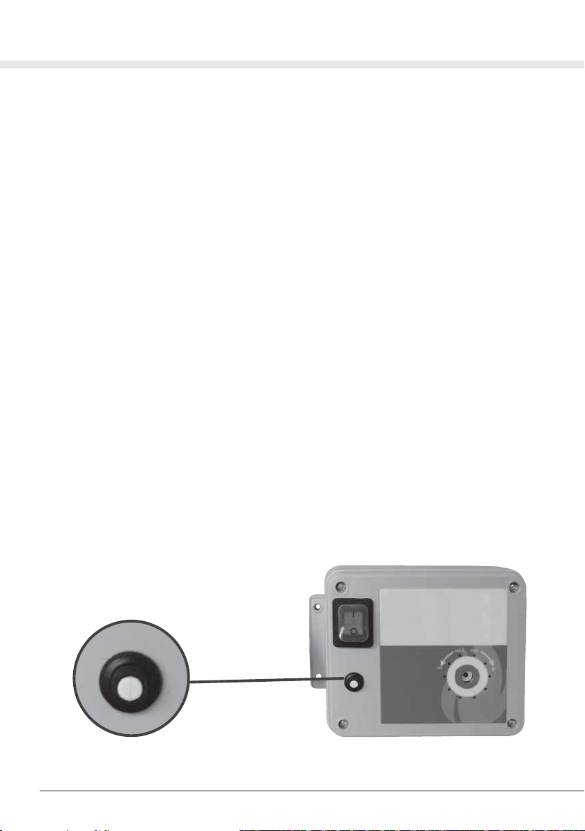
The thermal breaker 8 A (thermal switch) positioned on the control panel (see figure 28) has the
task of protecting the electrical and electronic parts of the system from any current surges and short
circuits. During correct operation, the circuit-breaker button will be positioned inside its seat, while in
the event of protection intervention, the button will come out of its seat. The reset is done manually by
pressing the button, this operation is effective only if the cause of the break has first been eliminated.
If this circuit breakage occurs repeatedly, the intervention of a specialized technician is necessary
to ascertain the causes.
15 TROUBLESHOOTING
Figure 28
Table of contents
Popular Fireplace Accessories manuals by other brands

Focal Point
Focal Point FPFBQ395 Assembly and installation instructions

RealFlame
RealFlame C11810 manual

Quadra-Fire
Quadra-Fire EXPEDITION-I installation manual

New Buck Corporation
New Buck Corporation ZCBB owner's manual

Travis Industries
Travis Industries 98500677 quick start guide

Boulevard
Boulevard DVP72LKR-1 installation instructions

Hearth & Home
Hearth & Home BRICK-MI30 Refractory Installation Instructions

Hearth & Home
Hearth & Home Outdoor Lifestyles LPTK-ODPLAZA-L installation instructions

kozy heat
kozy heat NCK-LX22L-S30 quick start guide

IHP
IHP PCBE-42 quick start guide

FMI
FMI Mantel and Base W36TO Assembly and installation instructions

Selkirk
Selkirk DSP installation instructions


