6
RESOLUCIÓN DE PROBLEMAS
GRIFO DE UN MANGO
PARA LAVAMANOS
Modelos 528224, 527747, 528109
529081, 529115, 529214, 527440
525998, 525980, 525972
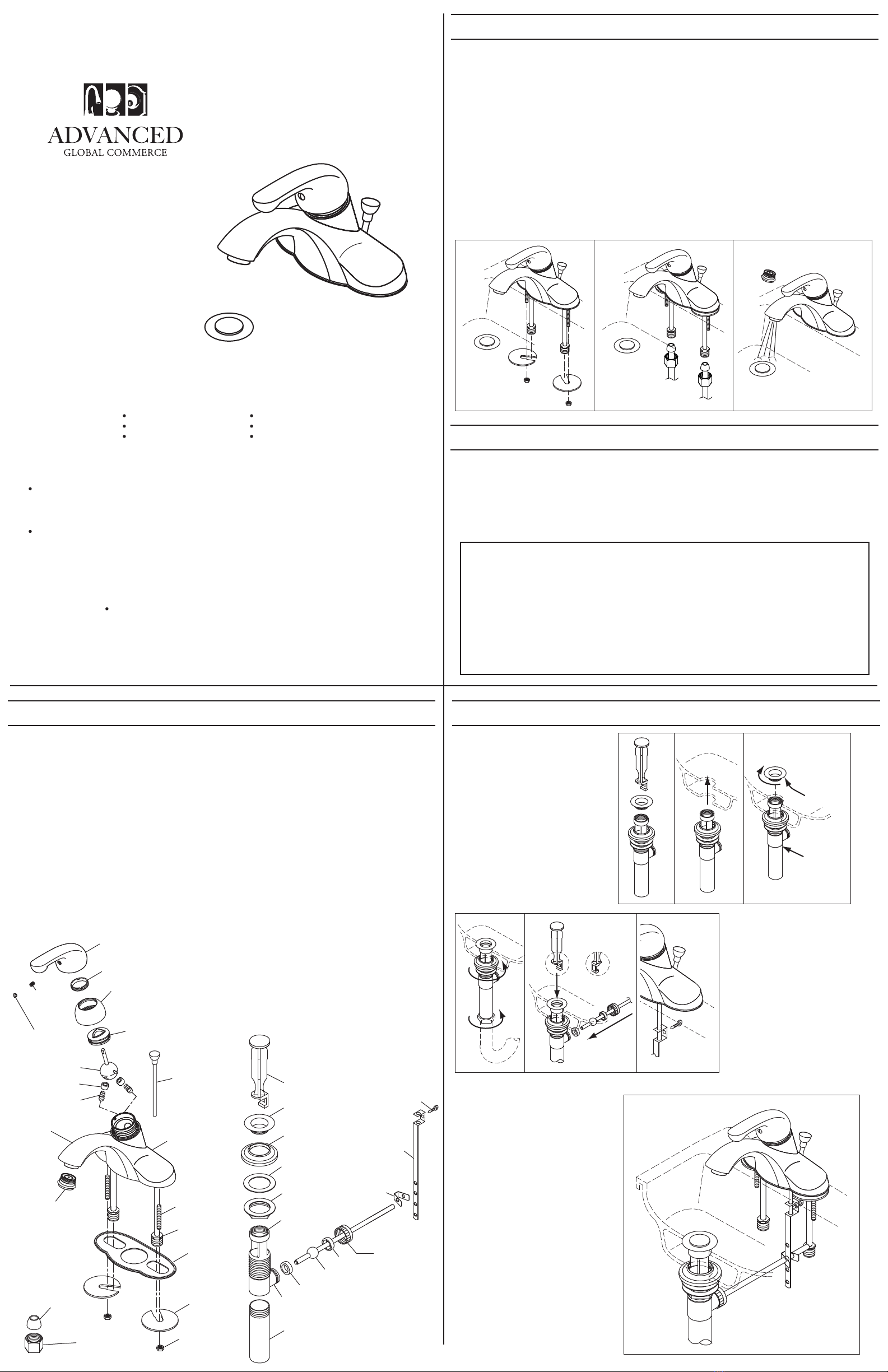
PROCEDIMIENTO DE INSTALACIÓN
EMPAQUE
CONTRATUERCA
ARANDELA
ARMAZÓN
DEL GRIFO
VARILLA
ROSCADA
ENTRADA
DE COBRE
RESORTE
BOQUILLA
ASIENTO
ENSAMBLAJE
DE LA BOLA
ENSAMBLAJE
DE LA LEVA
VARILLA DE
ELEVACIÓN
TUERCA DE TAPA
MANGO
TORNILLO
DE FIJACIÓN
TAPA
DEL INDICADOR
DE FRÍO/CALIENTE
AIREADOR
Muchas de estas partes ya vienen preensambladas.
Este diagrama expandido es para ayudarle
en la resolución de problemas.
PROCEDIMIENTO DE INSTALACIÓN CON EL DESAGÜE LEVADIZO (OPCIONAL)
TAPÓN DEL DESAGÜE
BRIDA
ARANDELA HELICOIDAL
ARANDELA
PLÁSTICA DE FRICCIÓN
CONTRATUERCA
PIEZA DE EXTREMO
BUJE
BUJE
VARILLA DE PIVOTE
CON BOLA
TUERCA
DE RETENCIÓN
PRENSA
DE
RESORTE
TIRA DE LA VARILLA
ABERTURA DE LA VARILLA DE PIVOTE
ARMAZÓN
DEL DESAGÜE
LEVADIZO
1. Quite el tapón y desenrosque la
brida del ensamblaje levadizo.
2. Inserte el armazón del desagüe
levadizo con la arandela helicoidal,
arandela plástica de fricción (no
incluida con los levadizos de plástico)
y contratuerca a través de la parte
inferior del desagüe del lavamanos.
3. Aplique sellador de silicona a la
parte inferior de la brida y enrósquela
en la parte superior del armazón del
desagüe levadizo. Desenrosque la
pieza de extremo. Agregue cinta de
teflón a la rosca de la pieza de
extremo y vuelva a acoplarla.
4. Apriete la contratuerca
asegurándose de que la arandela
helicoidal quepa en el agujero del
desagüe. Inserte la pieza de extremo
en el tubo de desagüe y apriete la
tuerca deslizante.
5. Inserte el tapón en la abertura del
desagüe en una posición en la que se
pueda quitar o no. Coloque el buje de
pivote dentro de la abertura de la
varilla de pivote. Coloque la varilla
de pivote con bola y el segundo buje
dentro de la abertura. Asegure con la
tuerca de retención. No apriete en
exceso.
6. Inserte la varilla de elevación a
través de la tira de la varilla. Apriete
con el tornillo de mano.
7. Inserte la varilla de pivote en el
primer agujero de la abrazadera de
resorte. Pase la varilla de pivote a
través de uno de los agujeros de la
tira de la varilla y asegúrela en el
segundo agujero de la abrazadera de
resorte.
8. Ajuste la altura de la varilla de
elevación aflojando el tornillo de mano,
posicionando la varilla de elevación y
reajustando firmemente el tornillo de
mano.
TORNILLO
DE MANO
INSTALACIÓN CON
DESAGÜE LEVADIZO
PARTES EXPANDIDAS
Sellador
de silicona
Cinta
de teflón
H
1
4 5
7,8
2 3
NON-
REMOVABLE
REMOVABLE
Problema: el grifo gotea alrededor del aireador o tiene un
flujo de agua incorrecto.
Causa: el aireador está sucio o inadecuadamente colocado.
Acción:
1. Destornille el aireador. Asegúrese de que todas las partes
internas estén colocadas de forma horizontal.
2. Si hay escombros, lave con cuidado todas las partes
internas.
3. Reinstale el aireador.
1. Desconecte el suministro del agua caliente y fría bajo el fregadero. Tape el drenaje con un trapo para evitar
perder partes pequeñas. Quite el grifo viejo.
2. Enrosque ambas varillas roscadas en
los receptáculos roscados ubicados
debajo del armazón del grifo.
3. COLOQUE EL EMPAQUE EN LA
PARTE INFERIOR DEL ARMAZÓN DEL
GRIFO ANTES DE INSTALAR EL
GRIFO EN EL LAVAMANOS.
Instale el grifo con el empaque a través
de los agujeros del lavamanos. Por
debajo del lavamanos, deslice las
arandelas de metal en las varillas
roscadas con las ranuras abiertas
alrededor de las entradas de cobre.
Luego enrosque las contratuercas en las
varillas roscadas. Asegúrese de que el
grifo esté en la posición correcta y
apriete las contratuercas.
4. ENVUELVA LA SECCIÓN
ROSCADA DE LAS LÍNEAS DE
COBRE CON CINTA DE TEFLÓN
ANTES DE CONECTAR LAS
LÍNEAS DE SUMINISTRO DE
AGUA.
Conecte la entrada de cobre a las
líneas de agua fría y caliente usando
tuercas de acoplamiento y
elevadores de ser necesario. Tenga
cuidado de no doblar ni plegar las
entradas de cobre. Las entradas
dobladas o plegadas anularán la
garantía.
5. Quite el aireador y abra las llaves del
agua. Permita que tanto el agua caliente
como la fría corran durante al menos un
minuto para desaguar el sistema de
cualquier escombro. Cierre las llaves y
vuelva a colocar el aireador.
6. Revise si hay fugas. Corríjalas
apretando levemente las conexiones. SI
LAS FUGAS PERSISTEN, CONSULTE
LA RESOLUCIÓN DE PROBLEMAS.
2,3 45
ANILLO DE AJUSTE
Problema: el chorro no se cierra completamente.
Causa: el asiento de hule de la válvula está sucio,
gastado o el anillo de ajuste o la tapa se han aflojado.
Acción:
1. Cierre las llaves del agua debajo del fregadero.
2. Quite el mango retirando el indicador de frío/caliente y
aflojando el tornillo de fijación con una llave allen.
3. Desenrosque la tuerca de tapa. Quite el ensamblaje de
la leva y de la bola.
4. Inspeccione si los dos asientos de hule de la válvula
tienen daños o basura. Reemplácelos de ser necesario.
5. Empuje los asientos de hule y los resortes hacia
adentro con los extremos más pequeños hacia arriba. Al
reemplazar la bola metálica, tenga cuidado de alinear la
clavija de metal ubicada a un lado del armazón con la
ranura oblongada de la bola metálica.
6. Vuelva a ensamblar el grifo teniendo cuidado de
colocar la lengüeta de alineación pequeña de la leva
dentro de la ranura.
7. Vuelva a apretar el anillo de ajuste. Vuelva a colocar el
mango y apriete el tornillo de fijación.
8. Abra las llaves del agua bajo el fregadero.
Problema: el grifo gotea bajo el mango.
Causa: está flojo el anillo de ajuste o el ensamblaje de
la tuerca de tapa.
Acción:
1. Quite el mango aflojando el tornillo de fijación con
una llave allen.
2. Apriete el anillo de ajuste girándolo en sentido de las
manecillas del reloj con un destornillador pequeño.
Mueva el tallo en bola a la posición de encendido y
apriete continuamente el anillo de ajuste hasta que el
goteo se detenga alrededor del tallo en bola.
3. Si el goteo no se detiene, afloje el tornillo de ajuste y
apriete el ensamblaje de la tapa girándolo en sentido
de las manecillas del reloj. Vuelva a apretar el anillo de
ajuste como estaba.
4. Vuelva a colocar el mango y apriete el tornillo de
fijación.
TUERCA
DE ACOPLAMIENTO (2)
ELEVADOR (2)
MANTENIMIENTO
Su nuevo grifo de Design House está diseñado para darle años de funcionamiento sin problemas.
Manténgalo viéndose como nuevo limpiándolo periódicamente con un paño suave. Evite usar
limpiadores abrasivos, lana de acero y químicos fuertes que opacarán el acabado y anularán la
garantía.
Los acabados en latón están pulidos y luego protegidos con una capa de laca para ayudar a prevenir
su pérdida de lustre. Limpie estas superficies solamente con un paño húmedo y suave.
GARANTÍA DE PROTECCIÓN DEL CONSUMIDOR
Bajo la Ley de Agua Potable Segura, la Agencia de Protección Ambiental de Estados Unidos
restringe la cantidad de plomo usado en el latón y la soldadura. Su nuevo grifo está hecho
cumpliendo estrictamente con todos los estándares gubernamentales.
Los materiales usados en la fabricación de este grifo son de calidad con estándar industrial y son
similares a otros productos de plomería que tienen conectores de latón.
Para reducir la cantidad de plomo en su agua potable, permita que el agua corra por un momento
antes de llenar su vaso y recuerde siempre usar agua fría para tomar.
Su nuevo grifo de Design House le dará años de funcionamiento sin problemas. Gracias por
escoger nuestro producto para su hogar. Por favor lea todas estas instrucciones con cuidado
antes de instalar su nuevo grifo.
Herramientas útiles para instalar este grifo:
PUNTOS IMPORTANTES
Cuando instale su nuevo grifo, apriete a mano las tuercas de conector, luego use una llave para
anclar el conector y otra para apretar la tuerca una vuelta más. Las conexiones que estén
demasiado apretadas reducirán la integridad del sistema.
Envuelva todas las conexiones roscadas (salvo la rosca del aireador en la boquilla) con cinta de
teflón - disponible en su ferretería local o en la tienda de suministros de plomería. Envuelva
siempre en dirección opuesta a la de las manecillas del reloj.
CONSEJOS DE SEGURIDAD
Proteja SIEMPRE sus ojos con gafas de seguridad.
Llave para lavabo
Cinta de teflón
Dos (2) llaves
Sellador de silicona
Linterna
Tubos de suministro para grifo


