manuals.online logo
Brands
  1. Home
  2. •
  3. Brands
  4. •
  5. Advanced ICE
  6. •
  7. Automobile Accessories
  8. •
  9. Advanced ICE 1324-1 User manual

Advanced ICE 1324-1 User manual

FOLLOW US
ADVANCEDICE1 ADVANCEDICE ADVANCEDICE ADVANCEDICE
WWW.ADVANCEDICE.COM.AU
This system is specically designed for adding a caravan camera to the factory screen and it will automatically switch to
the caravan camera once it is connected to the vehicle and the camera is powered up and generating a video signal.
When the caravan is unplugged from the car the system will revert to the normal factory reverse camera operation.
Jeep/Dodge Caravan
Camera Integration
1324-1_INS_V1.2
• This product comes with a 2 year warranty against manufacturer related defects.
• Only use with an NTSC camera. Some Jeep/Dodge Screens are not compatible with PAL type cameras.
• If this Installation requires opening the factory monitor or radio to insert ribbon cables or sub boards, Advanced
ICE Pty Ltd advises that the installation be carried out by an installer with experience working with electronic circuit
boards. Advanced ICE highly recommends the use of a suitable workbench with Antistatic Mat and Earth Strap to avoid
possible damage from a static charge. Advanced ICE Pty Ltd does not accept any responsibility for damaged
caused either to the components in the vehicle or the product, so please do not proceed with the installation if
you do not accept these terms.
• All labels on the product including software versions and serial numbers must not be covered, damaged or re-
moved. This may void the warranty on the product.
• Ensure that all left over accessories, including remote controls and cables, are given to the customer. If replace-
ments are required in the future they will be charged.
• Please ensure the installation of this product will not interfere with any factory safety equipment (e.g. Airbags)
• If working with Airbags, be sure to disconnect the vehicle Battery before beginning work. This product and the following
instructions are designed for installation by a qualied 12v installer, car audio installer or auto electrician.
• Interfaces and Navigation modules must not be installed in a location where they will be exposed to extreme
temperatures including, but not limited to, installation on top of a vehicles radio, transmission tunnel or rewall.
Damage caused by exposure to heat is not covered under warranty.
• If a navigation product is being installed, the end user will need access to the SD Card so as to perform navigation
software updates. Please ensure the navigation module is installed in an easy to access location.
• If the Navigation SD card is not easily accessible by the end user, you the seller, will be responsible for any labour
to assist the customer to access the SD card to perform navigation updates.
Important Product Information
Overview
PLEASE READ BEFORE BEGINNING INSTALLATION
Installation Terms & Conditions
Fig. 1 - CAN Box
Fig. 2 - Power Cable
Kit Content
Wiring Information
Fig. 4 - VSW Fig. 5 - V2P-II
Fig. 3 - USB Cable
PIN Description Colour
112 v (+) Constant Yellow
2INPUT 1: VIM Activation Red
3* NOT USED * Blue
4INPUT 3: Front CAM/Cargo
Cam (selectable) Pink
5RX (not present) --
6RCA MALE --
7RCA Sheild --
8CAN HI (Radio Side) Brown/White
9CAN HI (Car Side ) Blue/White
10 Ground (-) Black
PIN Description Colour
11 OUTPUT 1 Provides 12v (+)
ACC Out White/Red
12 OUTPUT (2) when AUX is
activated (AVSW V1 Trigger) Blue/White
13
OUTPUT (3) when Front
Camera is activated (AVSW
V2 Trigger)
Purple
14 TX INPUT (UART control to
SVS-6 RX) White/Brown
15 RCA Femal (Normally Open) --
16 RCA Female (Normally Closed) --
17 CAN LO (Car Side) Brown
18 CAN LO (Car Side) Blue
Fig. 6
Mode Change and Operation
Press the Back CAM icon to activate the camera while driving forwards Fig. 7
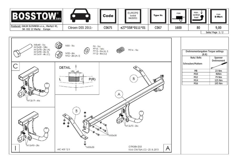
yGain access to the back of the monitor.
yUnplug the quad lock connector from the factory monitor and insert provided Plug and Play Quad Lock T Harness.
yIn the Plug and Play Harness, there are two yellow RCA connectors joined together. Disconnect these and do
the following:-
hConnect the female RCA from the vehicle side of the harness to the Male Video Output of VSW Video
Switch
hConnect the male RCA from the vehicle side of the harness to the VSW Video 1 Input
hThe Blue/White Trigger wire is not used for this installation and should be isolated.
hConnect the Black wire of the VSW to ground along with the Black wire from the V2P-II Interface
yConnect the White/Red Video 2 Trigger of the VSW to the Red Switched Power wire Output of the V2P-II
Interface. When a video signal is present on the RCA this wire will output 12v.
yConnect the Yellow 12v (+) of the V2P-II to ACC or Ignition.
yConnect the RCA Video Output of the V2P-II to the Video 2 Input of the VSW Video Switch.
yConnect the RCA Video cable from the caravan camera to the video female input of the V2P-II
To activate the front camera while driving forward simply double tap REAR Defrost Button on the radio.
Please refer to the wiring diagram on the next page (Figure 6) for more information.
Installation Guide
Tip: you can press and hold the icon on and drag to the bottom screen panel - this
keeps the camera button accessible at all times.
VSW V2P-II
CHRY
UNI-CAM v2
Video 1 Input
Video 2 Input
Video 3 Input
Video Output 12v (+)
ACC Input
Second Camera
Input
Red/White Video 2 Tr igger Connect to
ground
Connect to
ground
Blue/White
not used
Audio RCA
pass-through:
keep connected
unless using
Plug & Play T-Harness
Input 1
Input 3
Output 1
VIM & CIM
Enable
Input 2
Force Rear
Cam
Force Front
Cam
12v (+)
REV OUT
Output 2
12v (+)
FVC OUT
Output 3
12v (+)
ACC OUT
From OEM
Harness
Video Output
Switched Power
PLEASE NOTE:
Wire colours are subject to change without
notice. Please refer to PIN LOCATION
and/or Label for reference instead of colour.
Join wires
Not required for this application
Installation Overview - Caravan Camera
Fig. 8

Other Advanced ICE Automobile Accessories manuals

Advanced ICE 1435 User manual

Advanced ICE

Advanced ICE 1435 User manual

Advanced ICE NAV-FCA-P2 User manual

Advanced ICE

Advanced ICE NAV-FCA-P2 User manual

Advanced ICE 1435-1 User manual

Advanced ICE

Advanced ICE 1435-1 User manual

Advanced ICE 1469 User manual

Advanced ICE

Advanced ICE 1469 User manual

Advanced ICE 1409-2 User manual

Advanced ICE

Advanced ICE 1409-2 User manual

Popular Automobile Accessories manuals by other brands

Simple TranzitBLU HF Installation & operation manual

Simple

Simple TranzitBLU HF Installation & operation manual

Hiniker C-PLOW 8801 Operator's manual

Hiniker

Hiniker C-PLOW 8801 Operator's manual

Lampa SnowDrive Pilot-Pro Series Fitting instructions

Lampa

Lampa SnowDrive Pilot-Pro Series Fitting instructions

Whispbar K429W Fitting instructions

Whispbar

Whispbar K429W Fitting instructions

Rydeen DG240 Installation & user manual

Rydeen

Rydeen DG240 Installation & user manual

CrimeStopper CS-880.OEM install guide

CrimeStopper

CrimeStopper CS-880.OEM install guide

HOLDEN H831 instruction sheet

HOLDEN

HOLDEN H831 instruction sheet

BENDIX VORAD VS-400 Driver Instructions

BENDIX

BENDIX VORAD VS-400 Driver Instructions

Thule 4002XT manual

Thule

Thule 4002XT manual

Cequent Reese Elite Assembly instructions

Cequent

Cequent Reese Elite Assembly instructions

DK2 BCR790E user manual

DK2

DK2 BCR790E user manual

Enthuze ENT4078 manual

Enthuze

Enthuze ENT4078 manual

Germid QK-073A-1H4W-T23 user manual

Germid

Germid QK-073A-1H4W-T23 user manual

Fortin PASSLOCK-SL2 installation guide

Fortin

Fortin PASSLOCK-SL2 installation guide

Prorack K786 Fitting instructions

Prorack

Prorack K786 Fitting instructions

MAD DA2002 instruction manual

MAD

MAD DA2002 instruction manual

Hamron 326-052 User instructions

Hamron

Hamron 326-052 User instructions

Fortin EVO ONE THAR-ONE-HON6 Installation

Fortin

Fortin EVO ONE THAR-ONE-HON6 Installation

manuals.online logo
manuals.online logoBrands
  • About & Mission
  • Contact us
  • Privacy Policy
  • Terms and Conditions

Copyright 2025 Manuals.Online. All Rights Reserved.