Advanced ICE 1469 User manual

Page 1
1469_INS_V1.1
• All labels on the product including software versions and serial numbers must not be covered, damaged or removed. This
may void the warranty on the product.
• Ensure that all left over accessories, including remote controls and cables, are kept for future use. If
replacements are required in the future they will not be provided free of charge.
• Please ensure the installation of this product will not interfere with any factory safety equipment (e.g. Airbags).
• If working with Airbags, be sure to disconnect the vehicle Battery before beginning work. This product and the following
instructions are designed for installation by a qualied 12v installer, car audio installer or auto electrician.
• Interfaces and Navigation modules must not be installed in a location where they will be exposed to extreme
temperatures including, but not limited to, installation on top of a vehicles radio, transmission tunnel or rewall.
Damaged caused by exposure to heat is not covered under warranty.
PLEASE READ BEFORE BEGINNING INSTALLATION
Installation Terms & Conditions
This is a completely plug and play system and has been designed for the following vehicles and features:
2022 - Current Ford Ranger and Everest with the Sync 4A 12 Inch Screen. This system allows for the addition of up to four (4)
cameras to the factory screen
• This product comes with a 2 year warranty against manufacturer related defects. Please read the included
warranty card and register the device on the Advanced ICE Pty Ltd website.
• This installation manual covers a range of products and vehicles.
Overview
Important Product Information
Ford Ranger/Everest Camera
Integration Installation Guide
1469
Contents
Kit Contents 2
Interaction Connection Ports 2
Required Tools for Installation 2
Interface Dip Switch Settings 2
Camera Installation Scenarios 3
Wiring Information 4
Installation Process 4
Step 1 - Dash Removal 4
Step 2 -Multimedia Interface Installation 5
Step 3 - Test and Check 5
Mode Change and Operation 6
Interface Menu Settings 7
PARK Menu 8
Trouble Shooting & FAQs 9
Handle Button (Activation Button) 9
Page 2
• Dash and Trim Removal tools
• 7mm Socket Set
• Dash Protection Tape (Recommended)
• Picking Tool
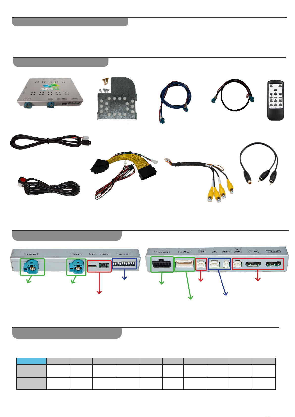
Infrared Eye (For Remote)
Interface
Mode Switch
LVDS Cable
LVDS Extension
Cable
Required Tools for Installation
Kit Contents
Please Note: You must remove power to the unit prior to making adjustments to the dipswitches.
When power is reconnected after the dip switch adjustment, the new settings will be stored into memory.
Interface Dip Switch Settings
Interaction Connection Ports
Dip SW: 1 2 3 4 5 6 7 8 9 10
UP/OFF -- OFF - OFF OFF - OFF - OFF
ON/DOWN ON ON -ON - - ON - ON -
Remote
Mounting Bracket
(6 x screws included)
LVDS
Extension
Cable
LVDS
Cable
90 Degree Programming
Ports
Not Used
Dipswitches
(see page 2) Connect
Power/CAN
T Harness Camera
AV Cable
Connection
Not Used
May be required
for product Setup
(see page 6)
Not Used
Power & CAN T
Harness Video Input Harness
WA7058
- RCA Y Adapter
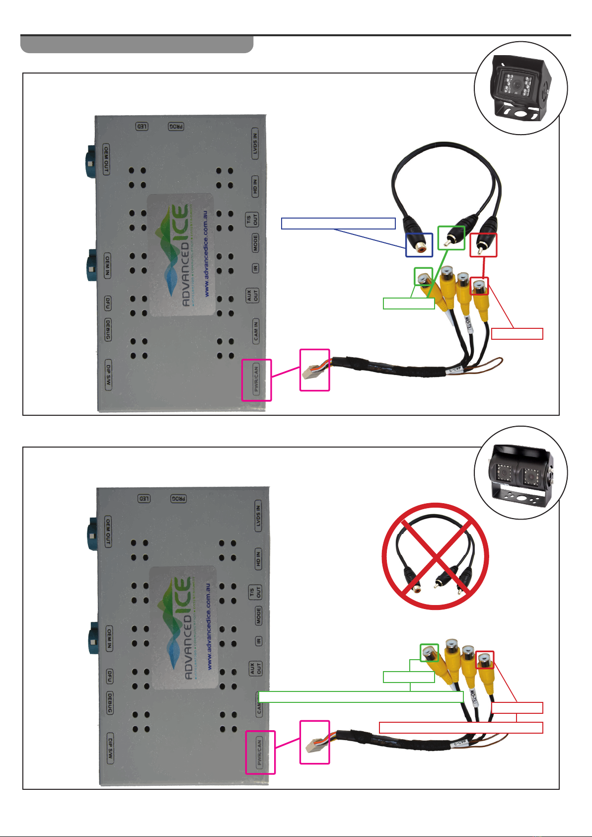
Page 3
Camera Installation Scenarios
SINGLE CAMERA INSTALLATION
Connect to Camera RCA
R - CAM
F - CAM
DUAL CAMERA INSTALLATION
R - CAM
F - CAM
Connect to Driving Forwards Caravan Camera
Connect to Reverse Caravan Camera
Page 4
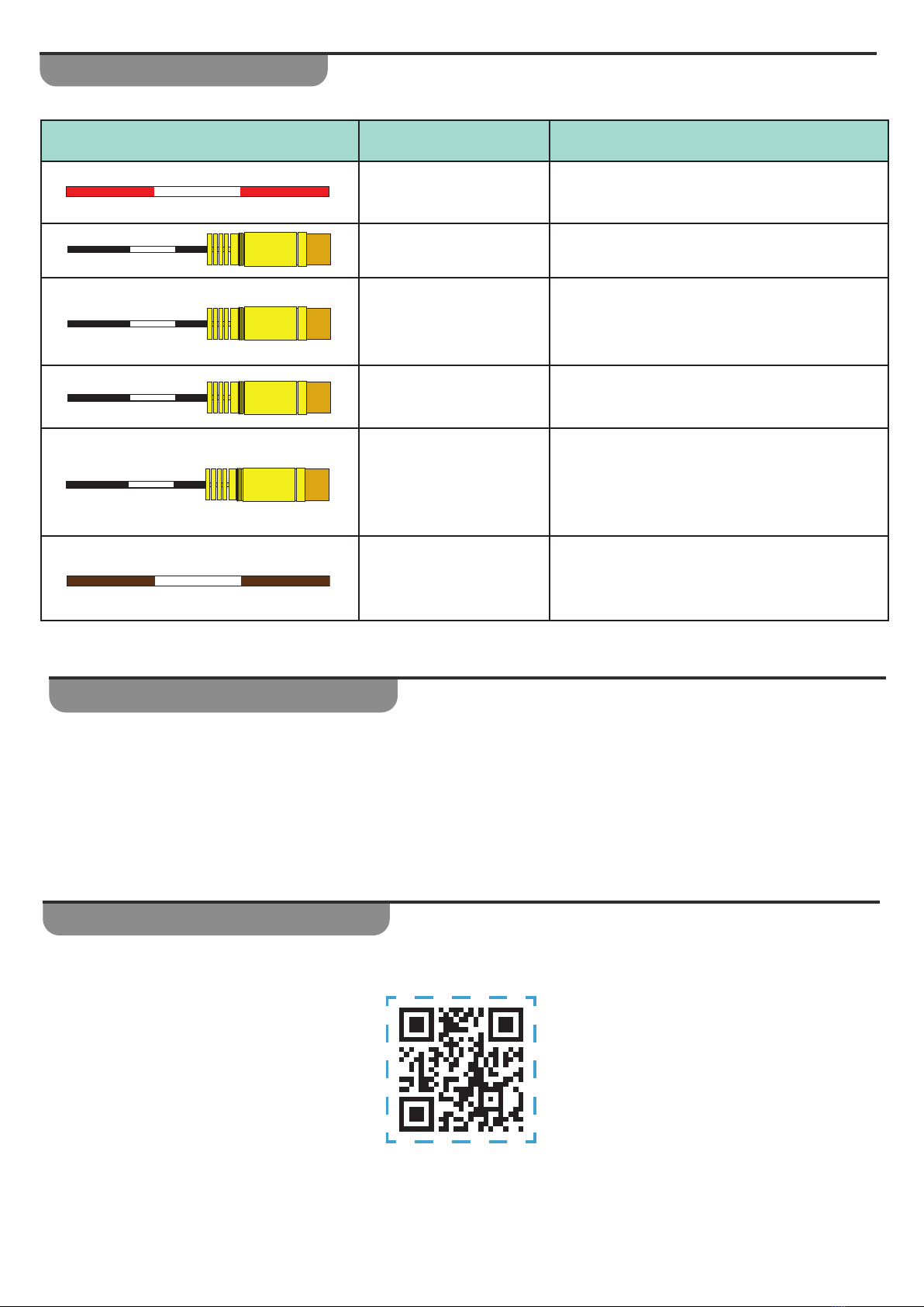
Wiring Information
Description Used For
ACC Power Wire This wire can be used to power up your
cameras
Video Input (F CAM) Connect Camera video signal for cameras
that can be viewed when driving
Video Input (R CAM)
Connect Camera video signal for cameras
that can be viewed when in reverse using
RTC (see user manual)
Video Input
(LET CAM)
Second or Left Camera video input that can
be viewed when driving
Video Input
(RGT CAM)
Third or Right Camera video input that can
be viewed when driving
Highbeam Output
This is a CAN-Bus generated Highbeam
output for use when installing Spot Lights or
Light Bars
ACC
LEFT CAM
LR-PWR
RIGHT CAM
R - CAM
F - CAM
Installation Process
PLEASE READ BEFORE CONTINUING
We strongly recommend taking appropriate steps (i.e. Masking Tape) to protect the factory screen, dash, steering
wheel and console. We also recommend covering the upholstery on the front seats.
Step 1 - Dash Removal
• Scan or click on the QR Code to watch the video on how to perform the dash removal in order to prepare for
the installation.
This video is a guide only and does not represent the exact process
on all Ranger & Everest Year/Model Variants.

Page 5
Step 2 -Multimedia Interface Installation
Please watch the entire video before beginning the installation.
If you are not comfortable with the technical nature of this installation,
we recommend taking it to a 12 volt professional to perform the installation for you.
• Scan or click on the QR Code to watch the video on how to prepare the product for installation and how to
connect it to the vehicle.
• Scan or click on the QR Code to watch the video on how to prepare the product for installation and how to
connect it to the vehicle.
• Before putting the vehicle back together we recommend making the following checks to make sure everything is
operating correctly
Check the factory system is powering on and working correctly
Check the Reverse Camera is working
Activate the Caravan Camera in Drive or Park (See Mode Change Instructions)
Check RTC Function is Working in Reverse (See Mode Change Instructions)
• When putting the Dash back together, remember to reconnect all disconnected plugs and make a test phone call
to ensure everything is functioning correctly
Ambient Light (if installed)
2 x USB Hub
Wireless Charging Pad (if installed)
Step 3 - Test and Check
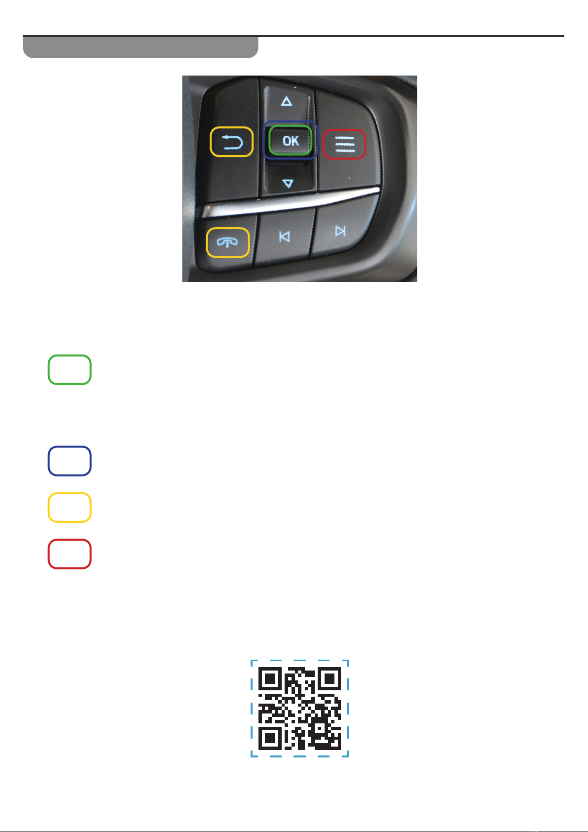
Page 6
When Driving
Long Press the OK button which is the systems Default Activation button to turn on the
Camera Source. If additional camera inputs have been activated, then additional long press of
this button will cycle through the camera inputs.
In Reverse
Long Press the OK button to switch from the vehicles factory reverse camera to the Camera
input of our interface.
These buttons can be used instead of the OK button to activate video sources.
(See Interface Menu Settings)
Short Press the OK button to return to the factory screen and switch o the camera source.
If the camera system stops responding a Longer 5 second Press of the Menu Button (Red) will
reset the camera system.
Scan or Click on the QR Code to see how the system operates
Mode Change and Operation
Page 7
Interface Menu Settings
In order to access the menu’s of our interface you will need to connect the Infrared
Eye to the interface and use the remote control.
1. Activate the camera interface so it is on the camera input
(a camera does not need to be reconnected)
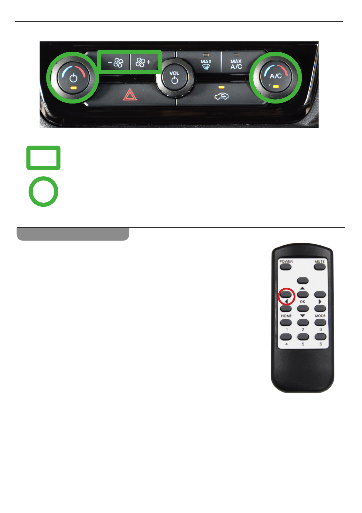
2. Point the Remote at the Infrared Eye and Long Press the Red Arrow Button
to access the menus
3. Use the Arrow Buttons on the Remote to navigate the menus and the OK
Button to conrm a change.
Do not make any other changes other than the ones listed below.
Climate Adjustments
When the Camera source is activated and one of the highlighted climate control functions are
adjusted, the system will automatically switch back to display the adjustment. After 5 seconds
from the last adjustment made, the system will automatically switch back to the camera
source.

Page 8
PARK Menu
In the Park Menu the following changes can be made
1. Side Type
Chne this from IRE DET to C -DET to enble the Left nd/or Riht Cmer inputs to be
ctivted with the crs Indictor.
Please note:
• Left and/or Right Camera’s need to be activated for this to function - see next step
• RTC (Camera in Reverse) function needs to be activated before the camera’s will turn on with the
indicators.
2. Side Function
This menu allows you to activate additional camera inputs
• CAM OFF - Default
One Camera input activated - This camera is always activated
• CAM2 (R)
This adds a second camera input visible when driving forwards and allows the right camera to be turned on by
indicator
• CAM3 (L)
This activates a second camera input and allows the left camera to be turned on by indicator
• CAM ALL
This activates all three camera inputs and allows the left and right camera to be turned on by the indicators
IMAGE
PARK
FUNC
UTIL
INFO
PAS TYPE
PAS SETUP
REAR TYPE
AUTO FCAM
SIDE TYPE
SIDE FUNC
NOT USED
CAN
OFF
WIRE DET
CAM OFF
:
:
:
:
:
Page 9
Trouble Shooting & FAQs
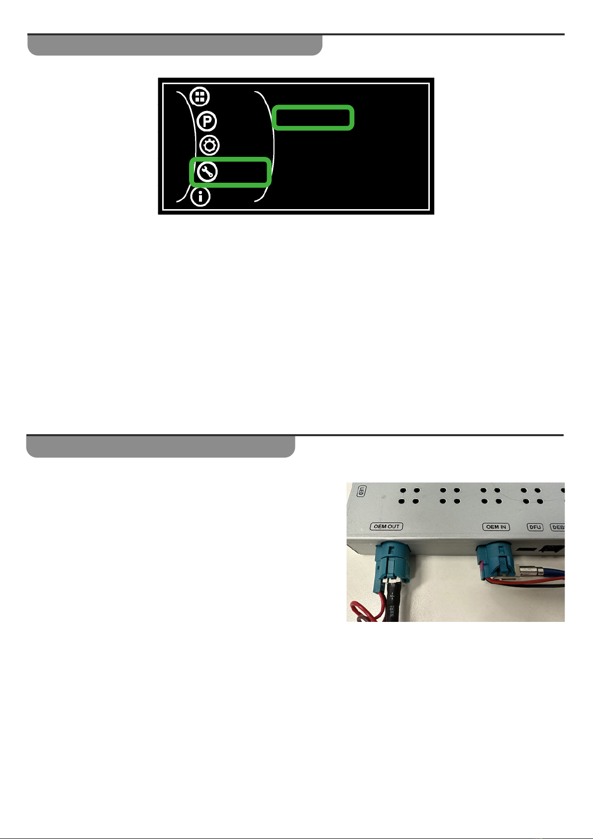
Q- After Installation the factory screen is blank and has not image.
A- Check the following:
• Ensure the LVDS Connections are correct as per the image.
• Ensure the dipswitches are set correctly
Handle Button (Activation Button)
Under the UTIL menu you can change the button on the steering wheel that is used to activate the camera source.
The options include the following:
1. OK - Default
2. PHONE - Phone button*
3. BACK - Return button
If the Phone button is selected as the activation button, then please note that if you are on a phone
call it will be ended if you long press the Phone button to activate the camera.
IMAGE
PARK
FUNC
UTIL
INFO
RESET ALL
HANDLE BTN
ACC OUT
NO
OK
HBEAM
:
:
:
Table of contents
Other Advanced ICE Automobile Accessories manuals


Popular Automobile Accessories manuals by other brands


FILTRON
FILTRON K 1096 installation instructions

SpeedTech Lights
SpeedTech Lights K-FORCE MICRO TOW 50 instruction manual

Or-Fab
Or-Fab HD Bumper installation instructions

Speedsignal
Speedsignal B-339MZ01 installation guide

Skoda
Skoda 000 072 549F user manual

Dakota Digital
Dakota Digital VHX Series Installation


