Advanced Navigation Certus OEM Owner's manual
Certus OEM
Certus Evo OEM
Supplement

Certus OEM Supplement
Page 1 of 23
Version 1.0
22 Jan 2021
Table of Contents
1 Revision History......................................................................................................................... 2
2 Firmware Changelog..................................................................................................................3
3 Hardware Changelog..................................................................................................................4
4 ntroduction.................................................................................................................................5
5 OEM Development Kit................................................................................................................6
5.1 Certus OEM Development Kit Contents..............................................................................7
6 Part Numbers and Ordering Options..........................................................................................8
6.1 Development Kits................................................................................................................8
6.2 Standalone Units.................................................................................................................8
6.3 Antennas.............................................................................................................................9
6.4 Accessories.........................................................................................................................9
7 Specifications........................................................................................................................... 11
7.1 Mechanical Drawings........................................................................................................11
7.1.1 Certus OEM Mechanical Drawings............................................................................11
7.1.2 Certus Evo OEM Mechanical Drawings.....................................................................12
7.2 Communication Specifications..........................................................................................13
7.3 Hardware Specifications...................................................................................................14
7.3.1 Certus OEM Hardware Specifications.......................................................................14
7.3.2 Certus Evo OEM Hardware Specifications................................................................14
7.4 Electrical Specifications....................................................................................................15
8 OEM ntegration.......................................................................................................................16
8.1 OEM Mechanical Mounting...............................................................................................16
8.2 OEM Electrical Connection...............................................................................................16
8.2.1 Connection Layout....................................................................................................17
8.2.2 Connection Schematic...............................................................................................17
8.2.3 Electrical connectors.................................................................................................18
8.2.4 Connection pin allocation..........................................................................................19
8.2.5 nteroperability with Different Voltage Systems..........................................................19
8.3 MMCX RF Connector........................................................................................................20
8.4 Onboard Memory Logging................................................................................................20
9 nstallation................................................................................................................................21
9.1 nstallation Checklist.........................................................................................................21
9.2 Power Supply....................................................................................................................21
9.2.1 9-30 V nput...............................................................................................................22
9.2.2 Regulated 5 V nput...................................................................................................22
9.3 Electrical Domains............................................................................................................22
9.4 Environmental Exposure...................................................................................................22
9.4.1 Temperature.............................................................................................................. 22
9.4.2 Water, Dirt and Dust..................................................................................................22
9.4.3 Shocks...................................................................................................................... 22

Certus OEM Supplement
Page 2 of 23
Version 1.0
22 Jan 2021
1 Revision History
Version Date Changes
1.0 22 January 2021 First Release
Table 1: Revision history

Certus OEM Supplement
Page 3 of 23
Version 1.0
22 Jan 2021
2 irmware Changelog
Certus OEM uses the same firmware as Certus Rugged, refer to the Certus Reference Manual for
change notes.
Note: Certus OEM requires a minimum firmware version of v1.44. Do not attempt to downgrade to
a lower firmware version as the unit may become unrecoverable.

Certus OEM Supplement
Page 4 of 23
Version 1.0
22 Jan 2021
3 Hardware Changelog
Version Date Changes
1.1 November 2020 nitial release
Table 2: Hardware changelog

Certus OEM Supplement
Page 5 of 23
Version 1.0
22 Jan 2021
4 Introduction
Certus OEM is a next-generation miniature GNSS / NS & AHRS system that provides accurate
position, velocity, acceleration and orientation under the most demanding conditions. t combines
temperature calibrated accelerometers, gyroscopes, magnetometers and a pressure sensor with a
dual antenna RTK GNSS receiver. These are coupled in a sophisticated fusion algorithm to deliver
accurate and reliable navigation and orientation.
Certus OEM will provide outstanding results when mounted, configured and operated correctly.
Please read through this manual carefully to ensure a successful outcome for your application.
The Certus OEM supplement is intended to be read in conjunction with the Certus Reference
Manual.
Certus is available in a number of variants. Any reference to Certus OEM can be assumed to refer
to either, with any specific exceptions noted.
•Performance: Certus, and Certus Evo base units are available with different MEMS
sensors, offering differing levels of Pitch & Roll, and Heading performance
•GNSS receiver: the standard GNSS receiver is an Advanced Navigation Aries. A Trimble
BD992 variant is also available
A Certus Development Kit is available that includes all the cables you will need to get you started
quickly. Optional antennas and accessories are also available for pruchase.
f you have any questions please contact [email protected].
Attention
Certus OEM is an electrostatic sensitive device and must be handled with care.
Precautions must be taken when operating the unit.

Certus OEM Supplement
Page 6 of 23
Version 1.0
22 Jan 2021
5 OEM Development Kit
Certus OEM is available in a Development kit contains everything required to get started operating
the system right away. The Development Kit is supplied in a rugged transport case to protect the
equipment during transit.
Note: Antennas and antenna cables are not included in the development kit, see section 6.3 for
ordering of antenna and antenna cable options
Illustration 1: Certus OEM Develo ment Kit trans ort case

Certus OEM Supplement
Page 7 of 23
Version 1.0
22 Jan 2021
5.1 Certus OEM Development Kit Contents
Part Number Quantity Description Notes
CERTUS-OEM,
CERTUS-OEM-BD992,
CERTUS-EVO-OEM,
CERTUS-EVO-OEM-
BD992
1 Certus OEM unit Model varies depending on kit
ordered
OEM unit includes non-
removable breakout board
BRL5521-JST 1 Power Socket 5.5x2.1 to
JST 35cm
DC power breakout cable to
barrel
RJ45FEM-MOLEX 1 RJ45 female to Molex
30cm
Ethernet breakout cable to RJ45
socket
MOLEX-P CO-3P N-30 5 Molex Pico-Spox cable,
3pin, female to female,
30cm
3-pin data breakout cable to
female Molex plug
Minimum Order Quantity 5
BF046WS140116-04 2 Female SMA to MMCX
Cable Assembly
For connecting external antenna
cable
SUPPLY-24V 1 24V DC Power Supply 100-240V AC Mains to 24V DC
Power Supply (DC jack)
ncludes 2-pin plug types A/C/G/
CERTUS-EK-CASE 1Transport case Rugged transport case

Certus OEM Supplement
Page 8 of 23
Version 1.0
22 Jan 2021
6 Part Numbers and Ordering Options
6.1 Development Kits
All OEM development kits include the items listed in section 5.1.
Note: antennas are not supplied as part of the development kit, see section 6.3 for antenna
selection
Part Number Description Notes
CERTUS-OEM-DK Certus OEM
Development Kit
Certus OEM Aries GNSS Development Kit
CERTUS-OEM-BD992-DK Certus BD992 OEM
Development Kit
Certus OEM BD992 GNSS Development Kit
CERTUS-EVO-OEM-DK Certus Evo OEM
Development Kit
Certus Evo OEM Aries GNSS Development Kit
CERTUS-EVO-OEM-
BD992-DK
Certus Evo BD992
OEM Development
Kit
Certus Evo OEM BD992 Development Kit
Table 3: Develo ment kit art numbers
6.2 Standalone Units
Part Number Description Notes
CERTUS-OEM Certus OEM Unit Certus OEM unit
Aries GNSS Receiver
CERTUS-OEM-BD992 Certus OEM BD992
Unit
Certus OEM unit
Trimble BD992 GNSS Receiver
GPS, GLONASS, L-band constellations
30cm RTK
CERTUS-EVO-OEM Certus Evo OEM
Unit
Certus Evo OEM unit
Aries GNSS Receiver
CERTUS-EVO-OEM-
BD992
Certus Evo OEM
BD992 Unit
Certus Evo OEM unit
Trimble BD992 GNSS Receiver
GPS, GLONASS, L-band constellations
30cm RTK
Table 4: Standalone unit art numbers

Certus OEM Supplement
Page 9 of 23
Version 1.0
22 Jan 2021
6.3 Antennas
The antennas listed below are available for purchase, for more information on antenna selection
see the section titled ‘GNSS Antennas’ of the reference manual for more details.
Part Number Description Notes
Cables
BF046WS140116-04 SMA to MMCX Cable
Assembly
SMA female panel mount to MMCX,
10cm cable
Connects breakout board to common
antenna connections
BF046WS180427-03 GNSS antenna cable 4
m
4 metre RG-58A/U SMA male to TNC
female antenna cable
Antennas
G5ANT-53A4T1 Antcom GNSS Antenna Antcom G5 L1/L2/L5 GNSS antenna
with survey mount, TNC Female
connector
Use with BF046WS180427-03
VSP6337L Tallysman VeroStar
GNSS Antenna
VeroStar GNSS Antenna - L1/L2/L5
plus L-band, pole mount, TNC Female
connector
Use with BF046WS180427-03
Antenna accessories
MOUNT-SUCT Suction Cup Antenna
Mount
Suction cup 5/8” GNSS antenna survey
mount for easy installation of GNSS
antenna on vehicles
6.4 Accessories
Part Number Description Notes
BRL5521-JST Power Socket 5.5x2.1 to
JST 35cm
Power Socket 5.5x2.1 to JST 35cm for
DC input power
RJ45FEM-MOLEX RJ45 Female to Molex
30cm
RJ45 female to Molex 30cm for
Ethernet connnection
MOLEX-P CO-3P N-30 Molex 3-pin F-F 30cm Molex Pico-SPOX cable, 3pin, female
to female, 30cm, for data connections
Up to 5 may be required
CERT-992-L C-10CM Upgrade Certus BD992
to 10cm RTK
Applicable for Trimble BD992 GNSS
Receiver variant

Certus OEM Supplement
Page 10 of 23
Version 1.0
22 Jan 2021
Part Number Description Notes
CERT-992-L C-8MM Upgrade Certus D992
to full RTK (8mm) with
Galileo and eiDou
Applicable for Trimble BD992 GNSS
Receiver variant
Adds Galileo and BeiDou GNSS
constellation support
SUPPLY-24V 24V DC Power Supply 100-240V AC Mains to 24V DC Power
Supply (DC barrel jack)
ncludes 2-pin plug types A/C/G/
CAR12VPWR Car auxiliary power
outlet supply
Car auxiliary power supply to DC jack
power supply
OBD -ODOMETER OBD Odometer OBD Odometer nterface
See the section “OBD Odometer
nterface” of the reference manual for
details
AD-UN T-LS (Low Speed)
AD-UN T (Standard)
AD-UN T-HS (High Speed)
Air Data Unit Air data unit provides pitot and static
air velocity data aiding for Certus in
fixed wing aircraft
Table 5: Accessories art numbers

Certus OEM Supplement
Page 11 of 23
Version 1.0
22 Jan 2021
7 Specifications
7.1 Mechanical Drawings
7.1.1 Certus OEM Mechanical Drawings
Illustration 2: Mechanical drawings of Certus OEM
4 x 3.1
75
68
61
93101.5
3.29
28.10
49.08
22.72
23.25
Primary MMCX
Secondary MMCX

Certus OEM Supplement
Page 12 of 23
Version 1.0
22 Jan 2021
7.1.2 Certus Evo OEM Mechanical Drawings
75
68
61
4 x 3.10
101.5 93
3.29
28.10
49.08
23.25
40.14
Primary MMCX
Secondary MMCX
Illustration 3: Mechanical drawings of Certus Evo OEM

Certus OEM Supplement
Page 13 of 23
Version 1.0
22 Jan 2021
7.2 Communication Specifications
Parameter Value
nterfaces Ethernet
UART
CAN
1PPS
Speed 100Mbit (Ethernet)
4800 to 4M baud (UART)
125000 to 1M baud (CAN)
Protocols AN Packet Protocol
NMEA 0183
NMEA 2000
TSS1
Simrad
Peripheral nterface 2x GP O for serial, timing, digital inputs/ outputs
GP O Operating Voltage Levels Disabled, 3.3 V, 5 V or RS232
GP O Port Serial nterface RS232
GP O Port Serial Speed 4800 to 250K baud
Default Primary, Auxiliary, GP O Serial Speed 115200 baud
Table 6: Communication s ecifications for OEM variants

Certus OEM Supplement
Page 14 of 23
Version 1.0
22 Jan 2021
7.3 Hardware Specifications
7.3.1 Certus OEM Hardware Specifications
Parameter Value
Operating Voltage 9 to 30 volts
nput Protection None
Power Consumption (typical) 2.64 W
Power Consumption (maximum) 4.5 W
Hot Start Battery Capacity > 48 hours
Hot Start Battery Charge Time 30 minutes
Hot Start Battery Endurance > 10 years
Operating Temperature -40 °C to 85 °C
MTBF 140,000 hours
Shock Limit 2000 g
Dimensions 75 x 101.5 x 24 mm
Weight 110 grams
Table 7: Hardware s ecifications for Certus rugged variant
7.3.2 Certus Evo OEM Hardware Specifications
Parameter Value
Operating Voltage 9 to 30 volts
nput Protection None
Power Consumption (typical) 2.9 W
Power Consumption (maximum) 5.0 W
Hot Start Battery Capacity > 48 hours
Hot Start Battery Charge Time 30 minutes
Hot Start Battery Endurance > 10 years
Operating Temperature -40 °C to 85 °C
MTBF 140,000 hours
Shock Limit 2000 g
Dimensions 75 x 101.5 x 40.2 mm
Weight 125 grams
Table 8: Hardware s ecifications for Certus Evo rugged variant

Certus OEM Supplement
Page 15 of 23
Version 1.0
22 Jan 2021
7.4 Electrical Specifications
Parameter Minimum Typical Maximum
UART
Tx Voltage Low 0 V
Tx Voltage High 3.3 V
Tx Short Circuit Current ±60 mA
Rx Threshold Low 0.6 V 1.2 V
Rx Threshold High 1.5 V 2.0 V
GPIO when set to 5 V
Output Voltage Low 0 V 0.3 V
Output Voltage High 4.8 V 5 V
nput Voltage -20 V 20 V
nput Threshold Low 1.5 V
nput Threshold High 3.5 V
Output Current 5 mA
1PPS when set to 5 V
Output Voltage Low 0 V 0.3 V
Output Voltage High 4.5 V 5 V
Output Current 50 mA
GPIO when set to 3.3 V
Output Voltage Low 0 V 0.3 V
Output Voltage High 3 V 3.3 V
Output Current 5 mA
nput Voltage -5 V 5 V
nput Threshold Low 0.8 V
nput Threshold High 2 V
1PPS when set to 3.3 V
Output Voltage Low 0 V 0.1 V
Output Voltage High 3 V 3.3 V
Output Current 50 mA
GNSS Antenna
Active Antenna Supply Voltage 4.5 V 4.6 V
Antenna Supply Current 200 mA
Table 9: Electrical s ecifications

Certus OEM Supplement
Page 16 of 23
Version 1.0
22 Jan 2021
8 OEM Integration
8.1 OEM Mechanical Mounting
The mechanical structure of Certus OEM forms an integral part of the OEM product in order to
provide rigidity, ensure factory calibration repeatability and performance accuracy. No mechanical
pieces should be removed from the Certus OEM product.
Certus OEM is secured using four M3 screws and washers and nuts on the back side of the
mounting surface. The length of the M3 screws will be depended on the thickness of the mounting
surface.
8.2 OEM Electrical Connection
The electrical connection to the Certus OEM is through Molex and JST connectors to board
mounted connectors.
Illustration 4: Mechanical drawing of Certus OEM mounting late
101.5
75
68
93
4 x 3.1
34
46.5
Certus OEM Supplement
Page 17 of 23
Version 1.0
22 Jan 2021
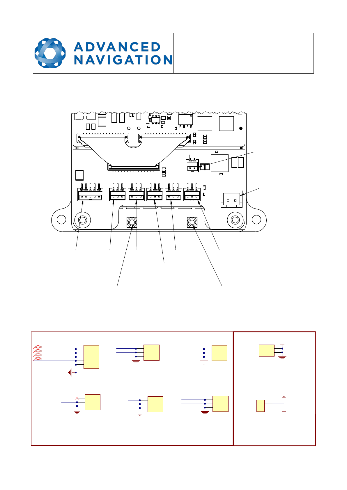
8.2.1 Connection Layout
The following illustration shows the connection locations on the Certus OEM unit.
8.2.2 Connection Schematic
The following illustration shows the schematic of the breakout connections.
Illustration 5: Certus OEM breakout connectors
Primary MMCX Secondary MMCX
Ethernet 1PPS
5
Power Input
AuxiliaryPrimary
CAN
GPIO
Illustration 6: Certus OEM breakout connectors
IO CONNECTORS
ETH
R_P
R_N
T_P
T_N 1
1
2
2
3
3
4
4
5
5
H2
0874370573
GND_ETH
Mating Connecto s
------------------------------
5pin: Molex 0874390500 (Digikey WM2089-ND)
3pin: Molex 0874390300 (Digikey WM2087-ND)
P ec imped wi es:
30cm: Molex 0797580016 (Digikey WM15726-ND)
15cm: Molex 0797580008 (Digikey WM12936-ND)
Mating Connecto s
------------------------------
2pin: JST XHP-2 (Digikey 455-2266-ND)
P ec imped wi es:
30cm: JST ASXHSXH22K305 (Digikey 455-3241-ND)
15cm: JST ASXHSXH22K152 (Digikey 455-3240-ND)
5cm: JST ASXHSXH22K51 (Digikey 455-3239-ND)
+5V
11
22
H8
0874370273
5V
GND
1PPS
1PPS
1
12
23
3
H3
0874370373
GND
GPIO1
GPIO2
GPIO
1
12
23
3
H4
0874370373
GND
CANL
CANH
CAN
1
12
23
3
H5
0874370373
GND
PRIM_TX
PRIM_RX
PRI
1
12
23
3
H6
0874370373
GND
AUX_RX
AUX_TX
AUX
1
12
23
3
H7
0874370373
GND
+SUPPLY
11
22
H1
B2B-XH-AM
9-30V
GND
POWER CONNECTORS

Certus OEM Supplement
Page 18 of 23
Version 1.0
22 Jan 2021
8.2.3 Electrical connectors
The following table describes the function of each connection and the type and ordering
information for connection. Certus OEM PCB Connector is the connector supplied on the Certus
OEM PCB ready for customer connection. Mating Connector for Cables is the manufacturers
mating connector and part number, plus the part number for a precrimped 15cm cable.
This information is provided to make it easier for you to design the appropriate type and length of
connections for your specific application. To make development easier, we also provide standard
~30cm pre-prepared as described in section 6.4.
Label unction Certus OEM
PCB Connector
Mating Connector for
Cables
9-30V 9-30V DC input power JST 2pin
B2B-XH-AM
JST XHP-2
(Precrimped wires: JST
ASXHSXH22K305)
5V 5V DC input power Molex 2pin
0874370273
Molex 0874390200
(Precrimped wires: Molex
0797580016)
PR Primary Serial UART
Molex 3pin
0874370373
Molex 0874390300
(Precrimped wires: Molex
0797580016)
AUX Auxiliary Serial UART
1PPS 1PPS communications
CAN CAN Communications Bus
GP O General Purpose nput/Output
ETH Ethernet network connectivity Molex 5pin
0874370573
Molex 0874390500
(Precrimped wires: Molex
0797580016)
PR M Primary GNSS antenna Female MMCX Male MMCX
SEC Secondary GNSS antenna Female MMCX Male MMCX
Table 10: Connector descri tions

Certus OEM Supplement
Page 19 of 23
Version 1.0
22 Jan 2021
8.2.4 Connection pin allocation
The following table shows the relevant pin allocation for each connection. Take care to accurately
identify Pin 1 when making cables/connections.
Connection Pin unction
Power nput
9-30V
1 Ground
2 Supply Voltage
5V 1 Optional 5 V input, see section 9.2.2
2 Ground
Primary
PR
1 Ground
2 Primary UART transmit
3 Primary UART receive
Auxiliary
AUX
1 Ground
2 Primary UART transmit
3 Primary UART receive
1PPS 1 Ground
2 1PPS
3 No Connection
CAN 1 Ground
2 CANL
3 CANH
GP O 1 Ground
2 GP O1
3 GP O2
Ethernet
ETH
1 Transmit positive +
2 Transmit negative -
3 Receive positive +
4 Receive negative -
5 Ground
Table 11: Connector in allocation table
8.2.5 Interoperability with Different Voltage Systems
All signals are 3.3 volt level, however inputs are tolerant to 5 volt signals from the target interface.
f you require a different voltage level to be compatible with your target system it is recommended
that you install a voltage level translator between the signals of each device.
This manual suits for next models
1
Table of contents
Other Advanced Navigation Antenna manuals

Popular Antenna manuals by other brands

1 BY ONE
1 BY ONE ODE00-0542 manual

One Forall
One Forall SV-9320 instruction manual

Wi-LAN
Wi-LAN LIBRA 5800 CPE user manual

Tri-Americas
Tri-Americas TracVision M7 Installation

M2 Antenna Systems
M2 Antenna Systems 450-800-12 Assembly manual

Somogyi Elektronic
Somogyi Elektronic home FZ 52 instruction manual

Wilson Electronics
Wilson Electronics SignalBoost DT installation guide

Planet Networking & Communication
Planet Networking & Communication ANT-FP14D installation guide

Newtronics
Newtronics G6-270R installation instructions

PreciseRF
PreciseRF HG3-plus EXPRESS user manual

DX Engineering
DX Engineering DXE-MBVE-5A instructions

MFJ
MFJ MFJ-1740 instruction manual


