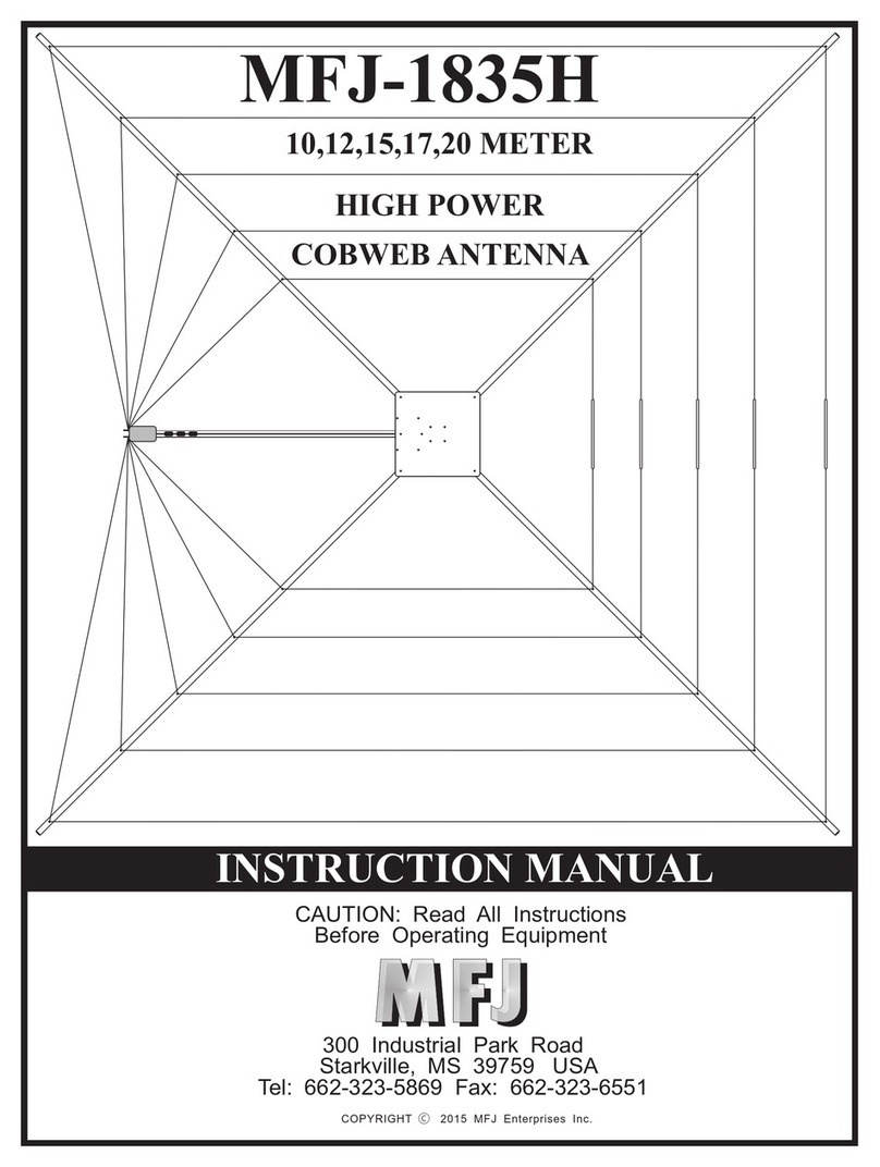
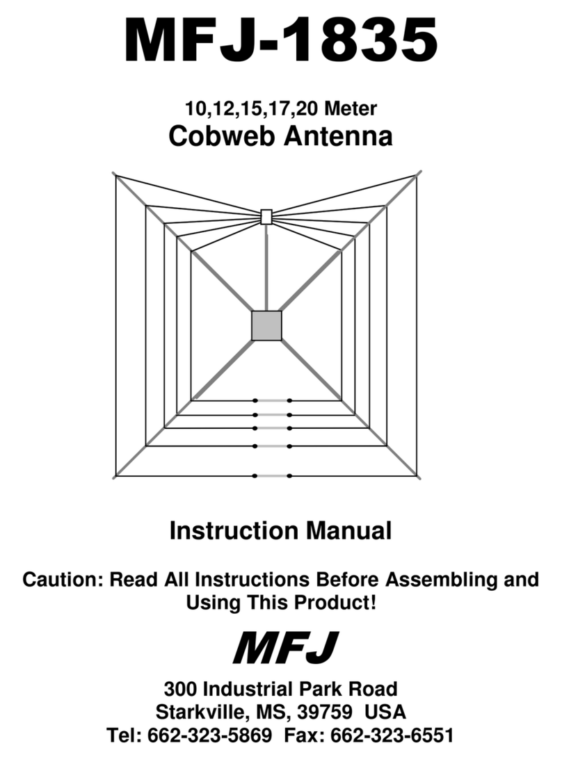
MFJ MFJ-1836 User manual

MFJ-1836,
MFJ-1836H
6,
10,12,15,17,20
Meter
Cobweb
Antenna
Instruction
Manual
Caution:
Read
All
Instructions
Before
Assembling
and
Using
This
Product!
MF
J
300
Industrial
Park
Road
Starkville,
MS,
39759
USA
Tel:
662-323-5869
Fax:
662-323-6551

MFJ-1836
(300-W)
and
1836H
"Cobweb"
(1500-W)
HF
Antenna
Introduction:
The
horizontally
polarized
MFJ-1836
and
MFJ-1836H
Cobweb
antennas
cover
20,17,15,
12,10,
and
6
Meters
in
a
compact
9-foot
by
9-foot
"neighbor-friendly"
package.
Both
are
carefully
designed
using
heavy-gauge
formed-aluminum
components,
stainless-steel
hardware,
and
premium
fasteners
to
deliver
years
of
trouble-free
performance.
Parts
List:
Before
beginning
assembly,
check
the
package
contents
against
the
parts
list
below
to
ensure
all
items
have been
included.
Materials:
8"
x
8"
Aluminum
Mounting
Plate
(737-1836)
72"
Fiberglass
Element
Support
Tube
(811-1836-1)
43"
Fiberglass
Feed
Tube
(811-1836-2)
50-Ohm
to
12.5
Ohm
Match
Box
(10-1836-1
or
10-1836-1H)
Mast-Mounting
Bracket
(735-1836)
Element
End-insulators,
12”
x
.5"
(737-0115)
Pack,
6-Meter
Element
Wire
(13-1836-6)
Pack,
10-Meter
Element
Wire
(13-1836-10)
Pack,
12-Meter
Element
Wire
(13-1836-12)
Pack,
15-Meter
Element
Wire
(13-1836-15)
Pack,
17-Meter
Element
Wire
(13-1836-17)
Pack,
20-Meter
Element
Wire
(13-1836-20)
Hardware
Pack
(17-1836-1)
Sa
a
eC
|
PC
NGG
Hardware
Pack
Contents:
[]
10
6-32
x
1-1/4"
screw
(656-1250S)
[]
20
6-32
x
1"
screw
(656-1000S)
[
]
4
6-32
x
1/2"
screw
(656-0500S)
[ ]
14
6-32
x
3/8"
screw
(656-0375S)
[]
52
6-32
nylon-insert
lock
nut
(705-0632S-NL)
Ey
4
6-32
Kep
nut
(705-0632S-k)
[]
38
#6
Flat
Washer
(561116)
[
]
2
U-Boit
Assembly
(758-9199)
{]
5
Cable
Tie
(745-2158B)
{]
4
#10
worm
clamps
with
hole
for
6-32
hardware
(030410)
If
any
parts
are
missing
or
damaged,
refer
to
the
Warrantee
page
for
replacement
instructions
and
have
the
MFJ
part
number
listed
above
available.
Preparation
and
Site
Safety:
To
assure
smooth
assembly,
sort
the
parts-bag
hardware
in
advance
and
follow
the
step-by-step
instructions.
Construction
through
Step-3
can
be
completed
almost
anywhere,
but
installing
the
spreaders
and
stringing
the
element
wires
will
require
a
flat
12-foot
by
12-foot
work
area.
For
initial
tuning,
mount
the
cobweb
5
to
6
feet
off
the
ground
on
a
temporary
mast
or
tripod,
and
be
sure
to
wear
safety
glasses
when
working
around
the
element
wires
and
spreaders.
Also,
enlist
a
helper
or
observer
for
final
installation,
and
never
work
near
power
lines
or
entrance
cables!

Important
Warning:
The
Cobweb
is
an
electrical
conductor.
If
it
comes
in
contact
with
power
lines
or
entrance
cables
during
assembly
or
installation,
you
could
be
KILLED.
Tools:
[ ]
5/16"
and
7/16"
nut
drivers
for
6-32
and
1/4-20
hardware.
[
]
Phillips-head
screwdriver
(#2)
[
]
Diagonal
cutters
or
"nippy"
shears
(for
trimming
cable
ties).
[
]
Safety
glasses
or
prescription
eye
protection
Pre-assemble
the
Antenna
Hub.
Use
the
parts
listed
below:
8"
x
8"
aluminum
base
plate
6-32
x
1-1/4"
screw
6-32
x
3/8"
screw
6-32
lock
nut
‘1:
[
[
[
[
[
43"
fiberglass
tube
aS
ee
yo
es
-OABRNNM
°
Mounting
Plate”
Mounting
fo
=
Bracket
<—
=
{
]
Install
the
mast-mount
bracket
using
four
3/8"
screws
and
nuts.
Insert
screws
as
shown
above:
Mounting
Plate
Install
Tube
Between
cou
the
Mounting
Plates
[>
Tube.
i
ty}
Lol
6-32
x
1-1/4"
[
]
Position
the
second
base
plate
opposite
the
first
so
all
mounting
holes
align.
Install
the
43"
feed
tube
by
sliding
it
in
between
the
two
plates.
Secure
using
two
1-1/4"
screws
and
nuts
(see
above):
2.
Install
the
Match
Box:
For
MFJ-1836:
Use
parts
listed
below
[
]
1
50-ohm
to
12.5
ohm
match
box
{ ]
1
6-32
lock
nut
[]
5
Cable
tie
wrap
Fomalo
UHF
Balun
G
tng]
Match
Box
Forritos
In-Line
ti
a
=a.
ll
Feod Tube
TaN
(3)
Se.
(=
i
=|
Hot
=
Mounting
Stud
oP
Baad
Tie-Wraps
~

[
]
Mount
the
match
box
at
the
opposite
end
of
the
feed
tube
using
a
6-32
nut.
Secure
the
coax
pigtail
with
three
cable
tie
wraps.
Note
that
the
box
mounts
on
top
side
of
the
feed
pole.
Use
the
remaining
two
cable
ties
to
secure
your
feedline
later
on.
For
MFJ-1836H:
Use
parts
listed
below.
[J
4
High-power
50-ohm
to
12.5
ohm
Match
Box
[]
2
6-32
lock
nuts
[
]
2
Cable
tie
wrap
7
,
Ne
|
Food
Tubo
es
a
Balun
=
ell
High-Power
Matching
box
Tio-Wraps
Farrites
if
J
ene
Elomont
Wire
Posts
[ ]
Mount
the
match
box
at
the
end
of
the
feed
tube
using
two
6-32
nuts.
Note
that
the
high-power
match
box
mounts
on
the
bottom
side
of
the
feed
pole
so
the
screened
air-
vents
will
face
toward
the
ground
when
the
antenna
is
installed.
Secure
the
feed
line
with
two
cable
tie
wraps.
Use
the
remaining
three
to
secure
your
feedline
later
on.
3.
Prepare
Spreader
Tubes.
Use
the
parts
listed
below.
ET
4
72"
fiberglass
element
support
tube
[
]
20
6-32
x
1"
screw
{
]
20
6-32
lock
nut
t]
20
#6
flat
washer
7
8-32
x
1"
(x5)
T
:
T
*
id
Flat
Washer(x&)
tT
Element
Support
Tube
o
o
™I~Ny-Lock
Nut
(x5)
@
[
]
Install
a
6-32
x
1"
screw
and
flat
washer
at
each
wire
attachment
point
on
all
four
spreader
arms.
Tighten
each
lock
nut
only
enough
to
retain
the
screw.
4.
Install
Spreaders
in
the
Base:
This
step
requires
a
12'x12'
flat
work
area.
Use
the
following
items:
[]
8
6-32
x
1-1/4"
screw
{]
8
6-32
lock
nut
When
installing
spreaders,
orient
so
the
wire-guide
washers
are
on
top.
[ ]
Loosen
(but
don't
remove)
the
two
nuts
securing
the
feed
tube.
[ ]
Loosely
install
all
four
spreader
arms
using
two
1-1/4"
screws
for
each.
[ ]
Once
all
four
spreaders
installed
are
in
place,
tighten
all
hardware
securely.
5.
Install
Mast-mount
U-bolts:
The
MFJ-1836H
matching
network
weighs
slightly
more
than
the
MFJ-1836
network,
so
the
mast
U-bolts
are
installed
differently
to
maintain
the
antenna's
center
of
gravity.

o
MFJ-1836
MFJ-1836H
For
MFJ-1836:
[
]
Install
the
two
U-bolt
assemblies
so
the
mast
inserts
inside
the
mast
mount
bracket.
For
MFJ-1836H:
[ ]
Install
the
two
U-bolt
assemblies
so
the
mast
inserts
on
the
outside
of
the
bracket.
6.
Install
Wire
Elements:
Before
you
begin,
mount
the
antenna
on
a
temporary
mast
or
tripod
with
the
base
5
or
6
feet
above
ground
(near
eye
level).
Wire
installation
will
begin
with
the
10-meter
(inner)
element
wires
and
work
outward
to
20
meters.
The
6-meter
element
will
be
installed
later.
Use
the
following
parts:
5
Insulator
strips
1
6-Meter
wire
pack
1
10-Meter
wire
pack
4
12-Meter
wire
pack
|
15-Meter
wire
pack
4
17-Meter
wire
pack
1
20-Meter
wire
pack
10
6-32
x
3/8"
screw
12
6-32
nut
a
10
#6
Flat
Washer
[ ]
Open
the
10-meter
wire
pack,
uncoil
the
wires,
and
carefully
remove
tangles
or
kinks.
[
]
Attach
the
element
wires
to
the
matchbox
terminals.
[
]
Start
a
6-32
nut
over
each
terminal
to
hold
lugs
in
place
while
stringing
the
wires.
[ ]
Route
element
wires
around
to
the
opposite
side
of
the
spreader
frame.
Catch
each
wire
under
the
inner-most
set
of
flat
washers
(see
below).
Do
not
tighten
screws
yet,
wires
should
remain
free
to
slide
back
and
forth.
String
wires
from
feedpoint
to
insulator
Pass
wire
underwasher:
secure
Wire
at
end
hole
|
Insulator
a
@
Do
not
tighten
nut
Insulator
Strip
Trim
for
desired
frequency

[
]
Connect
each
wire
to
a
insulator
strip
as
shown,
using
6-32
screws
and
nuts.
Be
sure
to
center
the
insulator
between
the
two
spreaders.
For
the
10-meter
element,
dimension
"D"
will
be
about
19".
When
setting
wire
tension,
minimize
but
do
not
completely
eliminate
wire
sag.
If
the
element
wires
are
pulled
too
tightly,
they
could
stretch
or
break
under
stress
when
the
frame
is
buffeted
by
high
winds.
Excess
wire
should
hang
straight
down.
These
ends
will
be
pruned
to
tune
the
antenna
in
Step
8.
Once
the
10
meter
element
wires
are
installed,
repeat
the
same
procedure
for
the
other
four
HF
bands.
As
you
add
additional
element
wires
to
the
match
box
terminals,
fan
the
ring
lugs
out
to
maintain
flat
metal-to-metal
contact
(see
below).
Fan
leads
so
lugs
make
full
surface-to-surface
[
]
Install
the
12-meter
loop.
Dimension
"D"
will
be
approximately
23-1/4"
[ ]
Install
the
15-meter
loop.
Dimension
"D"
will
be
approximately
28-3/4"
[
]
Install
the
17-meter
loop.
Dimension
"D"
will
be
approximately
34-3/4"
[
]
Install
the
20-meter
loop.
Dimension
"D"
will
be
approximately
45-3/4"
After
all
wires
are
installed,
check
each
for
even
tensioning.
Re-adjust
as
needed
to
ensure
no
wires
are
pulled
up
too
tight
or
hanging
too
slack.
Also,
confirm
that
the
frame
is
square.
When
satisfied,
tighten
down
all
wire-attachment
screws.
7.
Install
the
6-meter
element:
Note
that
installation
of
the
6-meter
element
may
be
omitted
without
impacting
operation
on
other
bands.
To
install,
use
the
following
items:
6-Meter
wire
pack
Worm-clamp
6-32
x
1/2"
screw
6-32
lock
nut
6-32
Kep
nuts
#6
Flat
Washer
opaARA
Prepare
all
four
6-meter
wire
guide
assemblies,
as
show
below:
Ny-lock
Nut
Flat
Washers
(2)
——
eS
Kep
Nut
Insert
[
]
Open
up
the
worm
clamp
(turn
hex-nut
counterclockwise
to
release
the
band).
[
]
Insert
6-32
x
1/2"
screw
though
hole
in
the
worm
clamp.
Secure
with
Kep
nut.
{
]
Install
two
flat
washers
and
a
nylon
locking
nut,
as
shown.

Unlike
the
other
five
elements,
the
6-meter
element
is
"corner-fed"
and
does
not
wrap
around
the
center
hub.
Install
as
shown:
Match
Box
Z—
Wire
Guide
(x4)
{ ]
Measure
(
6")
toward
the
center
hub
from
the
10-meter
element
guide
(see
above).
{
]
Install
a
worm-clamp
wire
guide
on
the
spreader
at
this
location.
[
]
Measure
(22")
beyond
this
guide
and
install
a
second
guide.
[ ]
Repeat
on
the
other
side
of
the
match
box.
en
Element
Wire
—
‘Fee
Flat
Washers
(2)
——
Spreader
Arm
fa
@
Worm-Clamp
[ ]
Install
the
6-meter
element
wires
on
the
match
box.
[
]
String
and
capture
the
element
wires
on
the
wire
guides,
as
shown.
»
Hang
the
excess
wire
straight
down,
avoiding
close
proximity
to
the
center
hub.
Like
the
other
elements,
these
ends
will
be
pruned
during
tune-up.
8.
Tune
Up:
The
cobweb
should
be
at
least
6
feet
above
ground
and
weather
conditions
dry
for
initial
tuning.
If
at
all
possible,
use
a
handheld
antenna
analyzer
for
measuring
SWR
and
pruning.
Also,
stand
a
few
feet
back
from
the
end
insulators
when
checking
to
avoid
deiuning
the
elements.
Important
Note:
|f
you
use
a
transmitter
and
SWR
meter
for
tune
up,
apply
the
minimum
power
needed
to
calibrate
the
bridge.
A/so,
never
touch
RF-energized
element
wires!
RF
burns
are
extremely
painful,
slow
to
heal,
and
can
be
inflicted
at
surprisingly
low
power
levels.
When
pruning
for
minimum
SWR,
trim
the
wire
ends
on
each
side
of
the
insulator
as
evenly
in
length
as
possible.
Also,
prune
in
small
increments
to
avoid
over-shooting
your
target
frequency.
You
may
find
one
or
more
minimum
SWR
readings
are
somewhat
elevated
with
the
antenna
in
close
proximity
to
ground.
These
readings
normally
drop
down
once
the
antenna
is
raised
higher.
Start
with
20
meters
and
work
inward:
[ ]
Find
the
initial
SWR
dip.
It
will
normally
occur
below
the
edge
of
the
band.
[ ]
Prune
wires
in
small
steps
to
obtain
minimum
SWR
on
your
desired
frequency.

[ ]
Once
tuned,
twist
the
wire
ends
tightly
to
prevent
individual
"hairs"
from
sticking
out.
For
MFJ-1836H:
Apply
solder
to
each
wire-end
to
prevent
it
from
fraying.
"Solidifying"
the
element
tips
with
solder
is
especially
important
at
high
power
levels
to
prevent
corona
or
sparking.
Repeat
the
above
tuning
procedure
on
the
other
bands:
[
]
Tune
17
meters
[
]
Tune
15
Meters
[
]
Tune
12
Meters
[
]
Tune
10
Meters
[
]
Tune
6
Meters
(if
installed)
Installation:
Cobwebs
perform
best
when
mounted
20-feet
or
more
above
ground
and
clear
of
nearby
wiring,
large
metal
surfaces,
or
other
antennas.
When
guying,
use
a
non-
conducting
line
such
as
Phillystran
or
black
Daycron.
The
U-bolts
accept
any
mast
diameter
between
1-1/4"
and
1-3/4"
OD.
Doubling
the
wall
thickness
is
recommended
for
longer
sections
of
un-guyed
mast.
Coax:
Premium-grade
RG-8X
feedline
works
well
up
to
1000
watts.
It's
easy
to
handle,
light
in
weight,
and
places
minimal
stress
on
the
support
mast.
For
higher
power,
use
RG-8,
RG-213,
or
a
premium-grade
equivalent.
Avoid
RG-58
except
for
short
cable
runs
and
portable
setups.
Safety
Ground:
Install
one
or
more
ground
rods
and
connect
them
to
the
mast
with
#10
solid
wire
and
stainless
hardware.
Coax
Disconnect:
Install
outside
the
building
and
unhook
coax
any
time
your
station
is
unattended
or
severe
weather
approaches.
It's
your
best
lightning
protection!
Using
a
Tuner:
The
cobweb's
folded
half-wave
elements
have
somewhat
less
bandwidth
than
straight-line
elements.
If
needed,
you
may
use
a
tuner
to
expand
low-
SWR
coverage
to
the
margins
of
the
wider
bands
(it
won't
harm
the
antenna).
Also,
be
aware
that
precipitation
loading
from
heavy
rain,
snow,
or
ice
accumulating
on
the
wires
will
temporarily
lower
resonant
frequency,
elevating
in-band
SWR
readings.
You
may
use
a
tuner
to
compensate
for
this
condition
during
weather-related
events.
Typical
Specifications:
Minimum
SWR:
Normally
1.2:1
or
less
on
all
bands,
measured
at
20'
AGL
Modeled
Gain:
4.7
dBi
at
20-feet
AGL
on
14.2
MHz
with
a
37°
TOA.
Modeled
Pattern:
+1.5
dB
with
maximum
gain
occurring
on
axis
with
the
feedpoint.
MFJ-1836
Power:
300-W
PEP,
SSB/CW,
ICAS
(<50%
transmit
time)
MFJ-1836H
Power
1500-W
pep,
SSB/CW,
ICAS
(<50%
transmit
time)
Balun
Ferrite-sleeve
"choke"
over
coax
Matching
Network
=
4:1
broadband
step-down
autotransformer
Dimensions:
9’
x
9'
per
side,
12'
diagonal.
Weight:
MF
J-1836
8.2
pounds,
MFJ-1836H,
8.8
pounds
Mast
Size
1-3/4"
OD
maximum

Warrantee
If
manufactured
by
MFJ
Enterprises,
Inc.
and
purchased
from
an
authorized
dealer
or
directly
from
MFJ,
we
warrant
to
the
original
owner
that
this
product
shall
be
free
from
defects
in
material
and
workmanship
for
a
period
of
12
months
from
date-of-purchase
provided
the
following
terms
and
conditions
are
satisfied:
1.
The
purchaser
must
retain
a
dated
proof-of-purchase
(bill
of
sale,
cancelled
check,
credit
card
or
money
order
receipt,
etc.)
describing
the
product
so as
to
establish
the
validity
of
the
warranty
claim.
In
addition,
the
original
copy
or
machine
reproduction
of
such
proof
shall
be
provided
to
MFJ
at
the
time
of
warranty
service.
MFJ
shall
have
the
discretion
to
deny
warranty
service
without
dated
proof-of-purchase.
Any
evidence
of
alteration,
erasure,
or
forgery
shall
be
cause
to
void
any
and
all
warranty
terms
immediately.
2.
MFJ
agrees
to
repair
or
replace,
at
its
option
and
without
charge
to
the
original
owner,
any
defective
product
under
warranty,
provided
the
product
is
returned
postage
prepaid
to
MFJ
Enterprises,
Inc.
with
a
personal
check,
cashiers
check,
or
money
order
in
the
amount
of
$7.00
to
cover
postage
and
handling.
3.
MFJ
Enterprises,
Inc.
will
supply
any
replacement
parts
free
of
charge
for
any
MFJ
product
under
warranty
upon
request.
A
dated
proof-of-purchase
and
a
$5.00
personal
check,
cashiers
check,
or
money
order
must
be
provided
to
cover
postage
and
handling
for
parts
and
materials.
4.
This
warranty
shal!
not
be
voided
for
owners
who
attempt
to
repair
defective
units.
Technical
consultation
is
available
by
calling
(662)
323-5869.
5.
This
warranty
does
not
apply
to
kits
sold
by
or
manufactured
by
MFJ
Enterprises,
inc.
(once
assembly
begins,
the
owner
becomes
the
manufacturer).
6.
Wired
and
tested
PC
board
products
are
covered
by
this
warranty
provided
only
the
wired
and
tested
PC
board
product
is
returned.
Wired
and
tested
PC
boards
installed
in
the
owner's
own
cabinet
or
connected
to
switches,
jacks,
or
cables,
etc.
and
sent
to
MFJ
Enterprises,
Inc.
will
be
returned
at
the
owner's
expense
un-
repaired.
7.
Under
no
circumstances
shall
MFJ
Enterprises,
Inc.
be
liable
for
consequential
damages
to
persons
or
property
by
the
use
of
any
MFJ
products.
8.
Out-of-warranty
Service:
MFJ
Enterprises,
Inc.
will
repair
any
out-of-warranty
product
provided
the
unit
is
shipped
prepaid.
All
repaired
units
will
be
shipped
COD
to
the
owner.
Repair
charges
will
be
added
to
the
COD
fee
unless
other
arrangements
are
made.
9.
This
warranty
is
given
in
lieu
of
any
other
warranty
expressed
or
implied.
10.
MFJ
Enterprises,
Inc.
reserves
the
right
to
make
changes
or
improvements
in
the
design
or
manufacture
of
its
products
without
incurring
any
obligation
to
install
such
changes
upon
products
previously
manufactured.
11.
All
MFJ
products
to
be
serviced
in-warranty
or
out-of-warranty
should
be
addressed
to
MFJ
Enterprises,
Inc.,
300
Industrial
Park
Road,
Starkville,
Mississippi
39759,
USA
and
must
be
accompanied
by
a
letter
describing
the
problem
in
detail
along
with
a
copy
of
a
dated
proof-of-purchase.
12.
This
warranty
conveys
specific
rights,
and
you
may
also
be
entitled
to
other
rights
which
may
vary
from
state
to
state.
This manual suits for next models
1
Other MFJ Antenna manuals

MFJ
MFJ MFJ-1625 User manual

MFJ
MFJ MFJ-1866 User manual

MFJ
MFJ MFJ-1838 User manual

MFJ
MFJ Super Hi-Q Loop MFJ-1786 User manual

MFJ
MFJ mfj-204b User manual

MFJ
MFJ MFJ-918BP User manual

MFJ
MFJ Mobile Big Stick MFJ-1652 User manual

MFJ
MFJ MFJ-2912 User manual

MFJ
MFJ Box Fan -1780 User manual

MFJ
MFJ MFJ-1432 User manual
Popular Antenna manuals by other brands

Channel Master
Channel Master 6392 Instruction and assembly manual

RF Venue
RF Venue 4 ZONE quick start guide

Philips
Philips SDW1420 Specifications

Sirius Satellite Radio
Sirius Satellite Radio SIR-WRR1 user guide

Ercogener
Ercogener EG-IoT-40B1 user guide

Beyerdynamic
Beyerdynamic AT91 operating instructions