Wi-LAN LIBRA 5800 CPE User manual


June 2003 Rev 0 3
Contents
Contents ........................................................................................................3
Important Information ................................................................................7
Safety considerations ..........................................................................................................7
Warning symbols used in this book 7
About this guide ..................................................................................................................8
Notices ...........................................................................................................9
Copyright notice .................................................................................................................9
Regulatory notice ................................................................................................................9
Other notices .....................................................................................................................10
Warranty & repair .............................................................................................................10
Customer support contacts ................................................................................................10
Distributor technical support 10
Contacting Wi-LAN Technical Support 11
Wi-LAN product information 11
Publication history ............................................................................................................11
Description ..................................................................................................13
Overview ...........................................................................................................................13
Libra 5800 Series System Features ...................................................................................13
About W-OFDM ...............................................................................................................14
About Point-to-Multi-Point (P-MP) Systems ...................................................................15
Access Point (AP) Equipment 15
Customer Premise Equipment (CPE) 16
Long Range Customer Premise Equipment (LCPE) 16
Radio Operation Background 17
About Point-to-Point (P-P) Systems .................................................................................18
Rapid Deployment (RD) Equipment 18
Extened Range (ER) Equipment 19

Contents
4 Libra 5800 Series User Guide
Hardware ...........................................................................................................................20
Specifications ....................................................................................................................24
Configuration ..............................................................................................27
Overview ...........................................................................................................................27
Accessing the Main Menus ...............................................................................................28
Access Methods 28
Setting VT100 Arrows 30
Powering up the unit .........................................................................................................32
Quick-Start Menu .............................................................................................................33
Exiting Setup 33
Unit Configuration: 34
Radio Configuration: 35
Communication Parameters: 35
Access Configuration: 37
OFDM Channel Statistics: 38
Link Test 38
PDA Setup Menu ..............................................................................................................39
Unit Configuration: 39
Radio Configuration: 40
Communication Parameters: 41
Setup Menu - Second Screen 42
Main System Menu ...........................................................................................................45
System Revision Information ...........................................................................................46
System Software ROM Images .........................................................................................48
Viewing system software ROM images 48
System Current Status .......................................................................................................48
Viewing system current status 48
System Security ................................................................................................................50
Setting Ethernet and wireless access to the TCP/IP Stack 50
Assigning Community Names 52
Setting Menu Passwords 53
Setting Auto Logout Timeout 59
System Commands ...........................................................................................................60
Setting Default System Image 60
Reboot Current Image 60
Rebooting a System Image 61
Restoring the Factory Configuration 62
Resetting MAC Layer Statistics 63
Network Configuration .....................................................................................................64
Setting the Internet IP Address 64
Setting the Internet IP Mask 65
VLAN Tagging 65
VLAN Tagging ID 67

June 2003 Rev 0 5
VLAN Tagging User Priority 68
Setting Local Network MAC Filtering (LNMF) 68
Radio Configuration .........................................................................................................70
Setting the RF Station ID (P-MP Only) 70
Setting the Sector ID 71
Setting the Synchronization ID 72
Setting the RF Center Frequency 72
Setting Tx Power 74
Setting the Modulation Type 75
Remote Station Configuration Menu (P-MP Only) ..........................................................76
IP/MBR Filter Configuration ............................................................................................78
Setting the IP Filtering Option 78
Configuring the IP Filter 79
Setting the MBR Filtering Option 81
MAC Layer Statistics ........................................................................................................84
Using the Command Line .................................................................................................86
Field Installation ........................................................................................89
Introduction .......................................................................................................................89
Libra 5800 field installation ..............................................................................................90
Site preparation 90
Tools and equipment 91
Libra 5800 installation procedure 93
Troubleshooting .........................................................................................97
Preventative maintenance .................................................................................................97
Troubleshooting areas .......................................................................................................98
Troubleshooting chart 98
Appendix A: Upgrading Software ..........................................................103
Background Information .................................................................................................103
Upgrading software via ftp .............................................................................................103
Rebooting the Unit Using Menu Commands 105
Rebooting the Unit Using FTP "Reboot" Files 105
Appendix B: SNMP MIB .........................................................................107
Overview .........................................................................................................................107
Obtaining SNMP Software .............................................................................................108
Using Wi-LAN MIB Object Identifier Nodes ................................................................108
System Commands 108
Network Configuration 109
Radio Configuration 110

Contents
6 Libra 5800 Series User Guide
System Security 112
IP Filter Configuration 112
System Current Status 113
MAC Layer Statistics 114
Appendix C: Simple Link Planning Worksheet ....................................117
AP (for P-MP) or Base (for P-P) Information ................................................................117
CPE (for P-MP) or Remote (for P-P) Information .........................................................118
Appendix D: Linktest and Link Statistics ..............................................119
Overview .........................................................................................................................119
Performing a Linktest .....................................................................................................119
Linktest variables 120
Appendix E: Bench Configuration Testing ............................................123
Overview .........................................................................................................................123
Setup process ..................................................................................................................123
Tools and equipment .......................................................................................................124
Checking shipping package contents ..............................................................................124
Assembling the Libra Units ............................................................................................126
Configuring the units ......................................................................................................127
Configuring a P-MP System 127
Configuring a P-P System 128
Testing the units ..............................................................................................................129
Testing the RF link with Linktest 129
Performing simple network tests 131
Glossary .....................................................................................................133
Index ..........................................................................................................145
Menu Map .................................................................................................153

June 2003 Rev 0 7
Important Information
Safety considerations
This document must be reviewed for familiarization with the product, instructions, and safety symbols
before operation.
Verify that local safety regulations are adhered to during installation with regard to grounding and
lightning protection.
Verify that the correct AC power source is available for the Power Inserter.
Disconnect the product from operating power before cleaning.
Warning symbols used in this book
WARNING: Injury or death may result from failure to heed a WARNING.
Do not proceed beyond a WARNING until the indicated conditions are fully understood and
met.
! CAUTION: Damage to equipment may result from failure to heed a caution.
Do not proceed beyond a ! CAUTION until the indicated conditions are understood and met.
Important: Indicates critical information to be aware of which may affect the completion of a task or
successful operation of equipment.
WARNING
All antennas must be installed by a knowledgeable and professional
installer.
! CAUTION
An antenna must be connected to the AP, LCPE or ER units before
powering up the equipment. Powering up equipment without an antenna
connected can permanently damage the unit or the RF transmission cable
!
!

Important Information
8 Libra 5800 Series User Guide
About this guide
This guide describes the common features of the Libra 5800-Series Broadband Wireless Access
System family of products from Wi-LAN Inc.
This guide is organized in the following sections.
Description,page 13, explains Broadband Wireless Access, the theory behind W-OFDM, how a BWS
system operates, and the function of the various parts.
Configuration,page 27, describes how to configure the units so they will function as part of their new
network.
Field Installation,page 89 guides you through the process of setting up Customer Premise
Equipment units.
Troubleshooting,page 97, explains how to fix some of the most common problems.
Appendix A: Upgrading Software,page 103, tells how to upgrade software.
Appendix B: SNMP MIB,page 107, explains the Simple Network Management Protocol software
used to remotely control the APs and CPEs.
Appendix C: Simple Link Planning Worksheet,page 117, gives a worksheet for calculating the link
budget for a simple situation.
Appendix E: Bench Configuration Testing,page 123, explains how to set up the BWS units in a
controlled environment such as a lab, configure them and test their basic operation.
Glossary,page 133, explains product terminology.
Index,page 145, can be used to quickly locate information on particular topics.
Menu Map,page 153, shows the Main System Menu and its submenus.
! CAUTION
Change the passwords and community names as soon as possible. Default
community names and passwords given in this book are provided to all customers and
are not secure.

June 2003 Rev 0 9
Notices
Copyright notice
Copyright©July 2003 Wi-LAN, Inc.
All rights reserved.
This guide and the application and hardware described herein are furnished under license and are
subject to a confidentiality agreement. The software and hardware can be used only in accordance
with the terms and conditions of this agreement.
No part of this guide may be reproduced or transmitted in any form or by any means – electronic,
mechanical, or otherwise, including photocopying and recording – without the express written
permission of Wi-LAN, Inc.
While every effort has been made to ensure that the information contained in this guide is correct,
Wi-LAN, Inc. does not warrant the information is free of errors or omissions.
Information contained in this guide is subject to change without notice.
Regulatory notice
The specifications and parameters of the device described in this document are subject to change
without notice.
For Canadian regulatory information, go to www.ic.gc.ca. For American regulatory information, see
www.fcc.gov. For European regulatory information, see www.etsi.org.
This equipment generates, uses and radiates energy on radio frequencies and, if not installed and
used in accordance with this guide, may cause harmful interference to radio communications.
However, there is no guarantee that interference will not occur in a particular installation.

Notices
10 Libra 5800 Series User Guide
If this equipment does cause harmful interference to radio or television reception, which can be
determined by turning the equipment off and on, the user is encouraged to correct the interference
by one or more of the following methods:
• reorient or relocate the receiving antenna
• move the equipment and receiver farther apart
• connect equipment to an outlet on a circuit different from that to which the receiver is
connected
Other notices
Changes or modifications to the equipment not expressly approved by Wi-LAN, Inc., could void the
user’s authority to operate the equipment.
Appropriately shielded remote I/O serial cable with the metal connector shell and cable shield
properly connected to chassis ground shall be used to reduce the radio frequency interference.
All antenna installation work shall be carried out by a knowledgeable and professional installer.
The parts in some Libra 5800 versions are Imperial sizes – inches and fractions of a inch. Do not
attempt to mix Imperial nuts, bolts and screws with similar metric hardware. This will strip the
threads.
Warranty & repair
Please contact the party from whom you purchased the product for warranty and repair information.
Wi-LAN provides no direct warranty to end users of this product.
Customer support contacts
Users of Wi-LAN equipment who require technical assistance must contact their reseller or
distributor. For information on distributors in your area, please visit www.wi-lan.com/channel.
Distributor technical support
Distributors may contact Wi-LAN’s Technical Support on Wi-LAN’s products.
When requesting support, please have the following information available
• configuration of the system, including models of Wi-LAN equipment, versions and serial
numbers
• antenna type and cable lengths
• site information, including possible RF path problems, such as trees, buildings and other RF
equipment in the area
• distance of the RF link
• configuration of unit.
• description of the problem

Publication history
June 2003 Rev 0 11
Contacting Wi-LAN Technical Support
Wi-LAN product information
To obtain information regarding Wi-LAN products, contact the Wi-LAN distributor in your region, or
call
1-403-273-9133 to speak with a Wi-LAN sales representative or visit our web site at www.wi-
lan.com.
Publication history
By Telephone Call: 1-403-273-9133
Business hours: 8:00 a.m. to 5:00 p.m. Mountain Standard Time (GMT - 7)
By e-mail Send an e-mail message to:
techsupport@wi-lan.com
Revision Date Description
Rev 1 July 2003 First public release of this manual.


June 2003 Rev 0 13
Description
Overview
This information in this guide applies to the "LIBRA 5800" Series products, including the following.
This chapter presents an overview of the LIBRA 5800 Series product.
Libra 5800 Series System Features
• Point-to-Point (P-P) system: Rapid Deployment (RD) units with integral 23 dBi antena or
Extended Range (ER) units with N-Type (F) RF connector for use with high gain external
antenna.
• Point-to-Multi-Point (P-MP) system: Access Point (AP) with N-Type (F) RF connector for use
with external sectoral, omni or other antennas, Customer Premise Equipment (CPE) with
integrated 23 dBi antenna and Long Range CPE (LCPE) with N-Type RF connector for use
with high gain external antenna
• fast transmission speeds–up to 32 Mbps raw data rate in 10 MHz channel (12.5 MHz
separation)
• Efficient use of spectrum
• cost-effective–wireless solution is inexpensive compared to wire line alternatives
• fast and easy to deploy
• enhanced multipath capabilities enable non-, near- and obstructed-line-of-sight operation
• operates in the unlicensed 5.8 GHz band
• advanced error recovery and signal processing
• easy-to-operate user interface and system configuration
Data Rate / Channel Size BWS Model Frequency (TDD System)
32 Mbps, 12.5 MHz channel separation Libra 5800 CPE TX&RX:5725-5850
32 Mbps, 12.5 MHz channel separation Libra 5800 LCPE TX&RX:5725-5850
32 Mbps, 12.5 MHz channel separation Libra 5800 AP TX&RX:5725-5850
32 Mbps, 12.5 MHz channel separation Libra 5800 RD TX&RX:5725-5850
32 Mbps, 12.5 MHz channel separation Libra 5800 ER TX&RX:5725-5850
Description
14 Libra 5800 Series User Guide
About W-OFDM
The Libra system uses Wi-LAN’s patented Wide-band Orthogonal Frequency Division Multiplexing
(W-OFDM) technology to process, transmit and receive data in parallel fashion over the air. W-
OFDM divides a wide RF frequency band into several subchannels that work together to deliver
data, similar to splitting a road into several lanes that together can handle more traffic than a single
lane.
W-OFDM offers many advantages, including effective use of bandwidth, resistance to interference,
ability to take advantage of multipath characteristics, and advanced error correction and recovery.
Because data is spread across all the channels, interference usually affects only a few channels
rather than all channels, and lost data can be easily recovered. Since W-OFDM is insensitive to
interference, the amount of ongoing tuning, adjustment and maintenance is minimized. Both
multipoint networks and point-to-point backbone systems are supported.
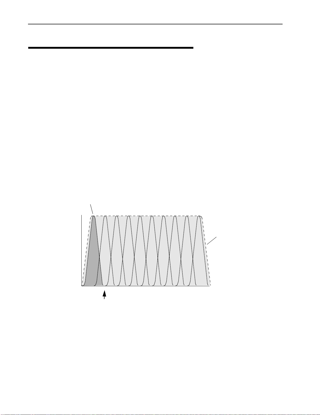
The following diagram illustrates the main concept behind W-OFDM. The available frequency
spectrum is divided into subchannels. Each subchannel is orthogonal, meaning that the peak signal
strength of each signal occurs at the null or point of minimum signal strength of its neighbor, so
adjacent subchannels do not interfere with each other. Data is carried in parallel across the
subchannels.
Orthogonal Arrangement of W-OFDM Subchannels
Signal Strength
Frequency
Subchannel (shaded for clarity)
Null
Zone
Operating
Frequency Range

About Point-to-Multi-Point (P-MP) Systems
June 2003 Rev 0 15
About Point-to-Multi-Point (P-MP) Systems
Two kinds of equipment are required for a wireless P-MP link: Access Point (AP) equipment and
Customer Premise Equipment (CPE). AP equipment is located at the service provider’s site and
CPE equipment is located at the customer’s site. The LIBRA 5800 P-MP product is available as an
AP, a CPE with integrated 23 dBi antenna or an LCPE for connection to higher gain external
antennas.
LIBRA 5800 P-MP System Components
Access Point (AP) Equipment
The AP controls communication within the wireless network and is the main access point to the
Ethernet.
The access point communicates with the CPE’s in the system to provide each CPE with Access to
the main network (ie Ethernet). The access point is typically located at a distance away from the CPE
that will provide adequate radio signal strength for the specified data rates.
Workstation
Hub
Computer
Sectoral Antenna
Access Point
Outdoor CAT-5
Cable
Power Inserter
CPE with
Integrated
Panel Antenna
Outdoor CAT-5
Cable
Power Inserter

Description
16 Libra 5800 Series User Guide
The Access Point is responsible for any CPE data management functions.
The Libra 5800 AP consists of three parts: 1) AP radio unit, 2) Ethernet Power Inserter with CAT-5
cable (bought separately) and weatherproofing kit (included), and 3) the External Antenna and cable
(both bought separately).
•LIBRA 5800 AP– The AP is the main piece of radio equipment. It is designed for outdoor
installation but can also be installed indoors if needed. The AP is equipped with an N-type (F)
RF connector so that the external antenna can be connected to it. Thus many different types
of base stations can be deployed using sectoral, omni or other specialized antennas.
•Ethernet Power Inserter– This piece of equipment is a small box that connects between the
CPE and the P.C. This box also provides power for the AP equipment to run. A CAT-5 outdoor
cable is used to connect the Power inserter to the AP. The weatherproofing kit is used with
standard RJ-45 connector to ensure reliable connection for outdoor systems.
•Antenna and Cable– In order to accomodate different frequency re-use plans and scalability
of the base stations the AP is designed to be used with an external antenna. Antennas and
cables are selected by the user based on the network requirements.
Customer Premise Equipment (CPE)
The CP equipment connects customers to the AP via a wireless link. The link enables customers to
communicate with other users of the wireless network and the Ethernet.
Customer Premise Equipment has two parts: 1) CPE radio unit and 2) Ethernet Power Inserter with
CAT-5 cable (bought separately) and weatherproofing kit (included).
•LIBRA 5800 CPE– The CPE is the main piece of equipment that would normally be installed
outdoors (indoor installation is permitted when feasible) The CPE contains all of the
necessary radio equipment to provide a high-speed wireless link. The CPE also has an
integral antenna such that no RF cables are required for a typical installation.
•Ethernet Power Inserter– This piece of equipment is a small box that connects between the
CPE and the P.C. This box also provides power for the CPE equipment to run. A CAT-5
outdoor cable is used to connect the Power Inserter to the CPE. The weatherproofing kit is
used with standard RJ-45 connector to ensure reliable connection for outdoor systems.
Wireless network activity focuses on the AP, which is both the main access point to the Ethernet
(LAN or WAN) and the destination for CPE-originated communications (CPEs do not communicate
directly with other CPEs—they communicate only via the AP). CPEs complete the customer-end of a
wireless link.
Long Range Customer Premise Equipment (LCPE)
The LCP equipment also connects customers to the AP via a wireless link. The LCPE enables the
customer to reach longer ranges by allowing the connection to a higher gain external antenna. It can
also be used for indoor installation of the units should severe weather conditions require it. The
antenna is then mounted outdoors and connected via appropriate RF cables to the unit. One other
alternative which customers may want to consider is to use lower gain antennas with systems that
are very close to the Base Station to mitigate some interference concerns without recourse to
dynamic power control.

About Point-to-Multi-Point (P-MP) Systems
June 2003 Rev 0 17
The Libra 5800 LCPE consists of three parts: 1) LCPE, 2) Ethernet Power Inserter with CAT-5 cable
(bought separately) and weatherproofing kit (included), and 3) the External Antenna and cable (both
bought separately).
•LIBRA 5800 LCPE– The LCPE is the main piece of equipment. It is designed for outdoor
installation but can also be installed indoors if needed. The LCPE is equipped with an N-type
connector so that the external antenna can be connected to it. Thus the range of the P-MP
system can be significantly increased by use of higher gain antennas. Also, in situations
where very severe conditions may be encountered outdoors the LCPE can be installed
indoors with cabling to the antenna outside.
•Ethernet Power Inserter– This piece of equipment is a small box that connects between the
LCPE and the P.C. This box also provides power for the LCPE equipment to run. A CAT-5
outdoor cable is used to connect the Power inserter to the LCPE. The weatherproofing kit is
used with standard RJ-45 connector to ensure reliable connection for outdoor systems.
•Antenna and Cable– In order to accomodate different range requirements for P-MP links,
the LCPE is designed to be used with an external antenna. Antennas and cables are selected
by the user based on the network requirements.
Radio Operation Background
The Libra 5800 communicates using a technique call Time Division Duplexing (TDD) in both the P-P
and P-MP configurations. TDD uses one frequency for both the Down Link (DL) Transmission (Base
to Remote in P-P, or AP to CPEs in P-MP), and for the Up Link (UL) (Remote to Base in PP or CPEs
to AP in P-MP). The DL and UL transmissions are performed at different times, therefore the system
is known as a Time Division Duplexing system. The available frequency band is therefore separated
into multiple TDD channels allowing for use of the whole frequency bands for very high capacity.
Time Division Duplexing Channels
In addition to using TDD, in a P-MP system, the AP and CPE also use Time Division Multiplexing
(TDM). TDM is a process of using time slots to allow the AP to transmit to multiple CPEs during a
single transmit cycle. During the Up Link cycle each CPE is polled and if it has data it transmits in
turn. This is known as Time Division Multiple Access (TDMA). All CPEs thus share the bandwidth
available by allocating time slots in turn to each of the units on both transmit and receive channels.
The following diagram shows TDM in a DL and TDMA in the UL. Each slot is allocated to a different
CPE. In the Wi-LAN system each slot may vary in time depending on traffic destined for each of the
CPEs. CPEs that are not very active will also be polled less frequently thus reducing the latency of
F1 F2 F3 ...... Fn
TDD Channels

Description
18 Libra 5800 Series User Guide
the system. Once they are ready to transmit or receive they will move up the polling list and will be
polled more often.
Time Division Multiplexing/Time Division Multiple Access (TDM/TDMA)
Antenna characteristics and placement are critical. Because of W-OFDM’s excellent Non-Line of
Sight performance and its resistance to frequency selective multipath fading CPE directional
antennas do not have to be pointed directly at the AP antenna. Having a clear line of sight is always
preferable, but is not necessary with the BWS series. There are cases in which the optimal
performance is acheived when the CPE antenna does not point directly to the AP (e.g. when using
reflection off a nearby structure to avoid an absorbing obstruction).
About Point-to-Point (P-P) Systems
For P-P systems Libra 5800 comes in two versions, the Rapid Deployment (RD) and the Extended
Range (ER) units. P-P links are used when only two locations are connected, for example for
backhaul purposes between P-MP Base Stations and the Network Operating Center for connection
to the Internet backbone, or in situations where throughput requirements between two locations are
such that the bandwidth can’t be shared.
Rapid Deployment (RD) Equipment
The RD equipment is intended for very rapid installation of a P-P link and can be used for links of up
to 16 kms (up to 12 kms at full 32 Mbps bandwidth).
RD Equipment has two parts: 1) RD and 2) Ethernet Power Inserter with CAT-5 cable (bought
separately) and weatherproofing kit (included).
•LIBRA 5800 RD– The RD is the main piece of equipment that is normally installed outdoors
(indoor installation is permitted when the range and link budget allows it) The RD contains all
of the necessary radio equipment to provide a high-speed wireless link. The RD also has an
integral 23 dBi antenna such that no RF cables are required for a typical installation.
•Ethernet Power Inserter– This piece of equipment is a small box that connects between the
RD and the Ethernet network. This box also provides power for the RD equipment to run. A
CAT-5 outdoor cable is used to connect the Power inserter to the RD. The weatherproofing kit
is used with standard RJ-45 connector to ensure reliable connection for outdoor systems.
DL
slot1
DL
slot2 UL SF1
...... DL slot-n
DL superframe
DL TDM
UL SF2 UL SFm
UL TDMA
UL superframes

About Point-to-Point (P-P) Systems
June 2003 Rev 0 19
Extened Range (ER) Equipment
The ER Equipment allows for the use of different external antennas to achieve links of much longer
range (up to 66 kms). It can also be used for indoor installation of the units should severe weather
conditions require it. The antenna is then mounted outdoors and connected via appropriate RF
cables to the unit.
The Libra 5800 ER consists of three parts: 1) ER, 2) Ethernet Power Inserter with CAT-5 cable
(bought separately) and weatherproofing kit (included), and 3) the External Antenna and cable (both
bought separately).
•LIBRA 5800 ER– The ER is the main piece of equipment. It is designed for outdoor
installation but can also be installed indoors if needed. The ER is equipped with an N-type
connector so that the external antenna can be connected to it. Thus the range of the P-P
system can be significantly increased by use of higher gain antennas. Also, in situations
where very severe conditions may be encountered outdoors the ER can be installed indoors
with cabling to the antenna outside.
•Ethernet Power Inserter– This piece of equipment is a small box that connects between the
ER and the Ethernet network. This box also provides power for the ER equipment to run. A
CAT-5 outdoor cable is used to connect the Power inserter to the ER. The weatherproofing kit
is used with standard RJ-45 connector to ensure reliable connection for outdoor systems.
•Antenna and Cable– In order to accomodate different range requirements for P-P links, the
ER is designed to be used with an external antenna. Antennas and cables are selected by
the user based on the network requirements.
Description
20 Libra 5800 Series User Guide
Hardware
This section describes the LIBRA 5800 hardware. Although antennas are part of the equipment in
general, antennas are not discussed here.
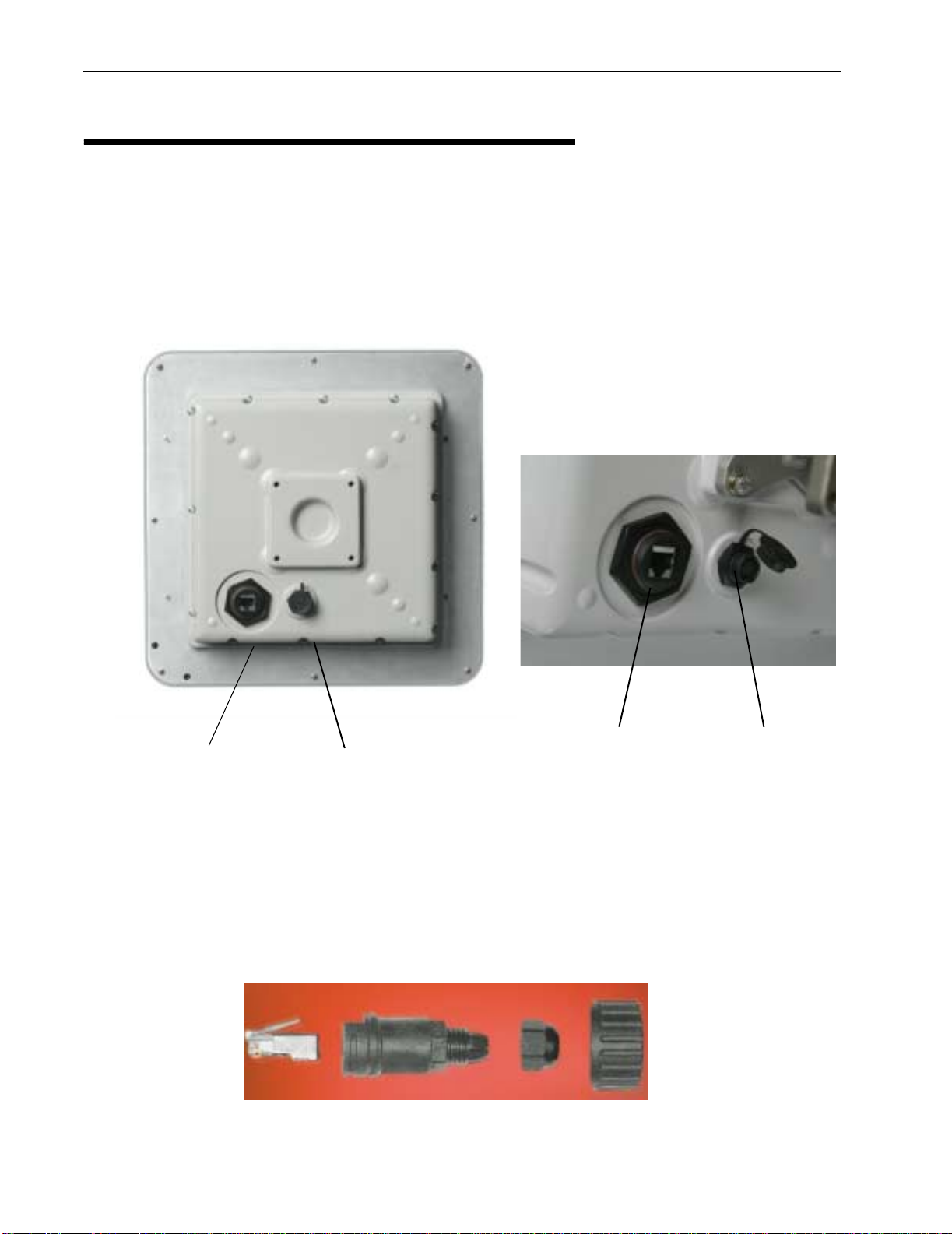
The LIBRA 5800 product has two connectors on the back panel. 1) Power/Ethernet Port 2) Serial
Port. The connectors are common for all types of Libra 5800 equipment. The AP, ER and LCPE units
also have a female N-Type connector on the front panel for connection to the antenna.
Libra 5800 Connection Panell
CAT-5 Weatherproofing Kit
Power/Ethernet Port Standard RJ 45 Ethernet Connector. A weatherproofing kit is provided
with the unit, so that standard outdoor CAT-5 cable can be used.
Serial Port 5-pin female connector. A matching connector and cable is available
separately for local configuration
Power/Ethernet Port
Serial Port
Power/Ethernet Port
Serial Port
This manual suits for next models
4
Table of contents
Popular Antenna manuals by other brands


LEAX
LEAX 0.9 m Antenna Installation instruction

Panorama Antennas
Panorama Antennas SW3-875 LGMQM4 Series Installation instruction

Solid
Solid Alliance_N2ROU user manual

Roadpro
Roadpro D3201 Installation and instruction manual

LEYBOLD
LEYBOLD 737 411 instruction sheet

Dressler
Dressler ARA-2000 Installation information