Advanced Radio Air Safe User manual
Air Safe
Failsafe Gear
Sequencer
User Guide

2
Table Of Contents
Introducon ---------------------------------------------------------------------------------------------------------------------3
Joysck controls and Important Points-----------------------------------------------------------------------------------3
Features --------------------------------------------------------------------------------------------------------------------------4
Air Safe Start-up Screen ------------------------------------------------------------------------------------------------------5
Run Mode Screen --------------------------------------------------------------------------------------------------------------7
Programming Main Menu Screen------------------------------------------------------------------------------------------8
Fail Safe Screen-----------------------------------------------------------------------------------------------------------------6
Sequencer Screen --------------------------------------------------------------------------------------------------------------7
Sequencer Outputs 1-6 and Programming --------------------------------------------------------------------------- 7-8
Sequencer Step Programming ----------------------------------------------------------------------------------------------9
Air Safe with Smooth Flite 26--------------------------------------------------------------------------------------------- 10
Important Sequencer Rules -------------------------------------------------------------------------------------------10-11
Warranty ---------------------------------------------------------------------------------------------------------------------- 12

3
Thank you for your purchase of the Advance Radio Air Safe Sequencer .
Air Safe was designed with Giant Scale Models in mind and combines a high quality
200 psi pressure sensor, a fail safe air monitoring system, a 6 channel Gear sequencer
with a built in daylight OLED screen and joysck programming.
In addion, if you are using the Smooth Flite 26 system then you can connect Air Safe to
the Smooth Flite to add fail safe pressure monitoring to the Smooth Flite main Gear se-
quencer.
LETS GET STARTED — in this guide we will show you how to get the most out of the Air
Safe system. Please take the me to read and understand this guide before installaon.
Joysck Control— Air Safe comes with a built in daylight OLED
and 5 way joysck.
Joysck ↑ UP Arrow — moves up between menu items.
Joysck ↓ DOWN Arrow — moves down between menu items.
Joysck → RIGHT Arrow — Increases a value.
Joysck ← LEFT Arrow — Decreases a value.
Joysck PRESS — Selects and item or new page.
Joysck PRESS on the word “RETURN” (at the top of the screen) will return you to a previous
page.
WARNING—Air Safe will power air valves, servos (for gear doors) and linear actuated
electric retracts i.e. retracts that connect with a servo lead. It is not designed to directly
power electric DC motor retracts.
MULTI CHANNEL USAGE—Air Safe oers up to 6 channels of gear and door sequencing.
In most cases with air systems 2 or 3 output channels are all that are required for most
retract setups. However, If you use a large number of output channels to power servos
or linear retracts YOU MUST PROVIDE ENOUGH INPUT POWER TO OPERATE THEM.
DUAL POWER INPUTS—Air Safe has 2 power inputs for larger power setups. The gear
channel input will provide power and a second input specically for addional power
connecon. For high power setups connect both the gear channel and the addional
baery connector to the receiver or Power Expander. DON’T connect a second baery
unless the second baery is the same voltage and type as the receiver baery.

4
Features and Specicaons:
• Built-in Air Guard Technology. Air Safe constantly monitors air pressure and
will perform a gear down sequence if the user set fail safe air pressure is
reached.
• 200 psi high quality absolute pressure gauge. Tested to 170 psi.
• Works with all major baery chemistries. LiFe. LiPo, Lion, NiMh,
NiCD. Baery voltage range can be from 6volts to 8.4volts.
• 6 channel sequencer with PWM outputs to run air valves, servos or linear
retracts.
• Easy-to-see daylight OLED screen for setup and pressure monitoring.
• 5 way joysck for easy programmability.
• servo normal/reverse on all channels.
• end point seng on all channels.
• Dual power inputs for larger setups.
• ARXL protocol output to connect to any Advanced Radio ARXL device to
send fail safe seng data.
• Stylish anodised aluminium case.
• Dimensions: 38mm x 18mm x 57mm. 1.5” x 0.7” x 2.24”
• Weight: 40grams. 1.4 oz

5
Screens and Usage
Air Safe Start-up Screen
When you rst power up the Air Safe you will see the start-up
welcome message with the soware version number. Aer a
short me the Air Safe will move to the Run Mode Screen.
ADVANCED RADIO
FAILSAFE GEAR
SEQUENCER
VERSION X.XX
Run Mode Screen
Run Mode Screen shows the pressure monitor, it gives feed-
back about system (absolute) pressure. It also shows the cur-
rent gear posion.
SYSTEM PRESSURE
150.0 PSI
GEAR POSITION
DOWN
PROGRAMMING MODE—To move to program-
ming mode press the joysck. This will take
you to the programming menu.
Programming Main Menu Screen
On the Programming menu use the joysck ↓ DOWN Arrow
and ↑ UP Arrow to move between the dierent menu
items. As you move between the dierent menu items the se-
lected item will be highlighted with a white background.
Select “FAIL SAFE” to go to the Fail Safe setup page.
Select “SEQUENCER” to go to the Sequencer setup page.
Select “FACTORY RESET” to go to the Factory Reset page.
Select “RETURN” to return to the previous page.
FAIL SAFE
SEQUENCER
FACTORY RESET
RETURN

6
Screens and Usage
Fail Safe Screen
This screen shows you the (LV) Live or absolute system
pressure as well as the selected (FS) Fail Safe pressure.
To set the Fail Safe pressure (the pressure at which the
gear will be triggered to the down posion) you:
1) Pump up the system pressure to the desired Fail
RETURN
FS 0.0 PSI
LV 70.0 PSI
Safe pressure.
2) Move the cursor to the “SET FAIL SAFE” menu
item and press the joysck once.
The “SET FAIL SAFE’ menu item will ash several mes
and the current system pressure will be captured as the
fails safe trigger pressure. The FS 0.0 PSI will take on
the value of the system pressure and the “SET FAIL
SAFE” menu item will change to read ”CLEAR FAIL
SAFE”. From this point forward if the system pressure
SET FAIL SAFE
RETURN
FS 70.0 PSI
LV 70.0 PSI
CLEAR FAIL SAFE
drops below the Fail Safe pressure a gear down event will be triggered.
You can clear the Fail Safe pressure highlighng “CLEAR FAIL SAFE” and pressing the joysck.
Please Note: system pressures lower than the Fail Safe pressure will not allow
you to run the sequencer to the up posion or allow system tesng during set-
up so it is advisable to set the Fail Safe pressure aer you have completed pro-
gramming the sequencer. You can clear the Fail Safe pressure trigger point at
any me by pressing “CLEAR FAIL SAFE”

7
Screens and Usage
Sequencer Screen
SEQUENCE DOWN/UP This feature allows you to man-
ually operate the sequencer without the need for the
TX to be switched on.
To use this feature move the cursor to the SEQUENCE
DOWN item.
THEN...
Sequencer Outputs 1-6
Selecng this menu item will take you to the output
setup screen.
Highlight and select any output to set up:
• Air valve end points, or reverse air valve funcon.
• Servo end points, or reverse servo funcon.
There is also a speed seng to slow servo travel.
Connued over page...
RETURN DOWN-1
SEQUENCER SETUP
SEQ OUTPUT 1—6
Joysck → RIGHT Arrow — Starts a Sequence to the up posion.
Joysck ← LEFT Arrow — Starts a sequence to the down posion.
Joysck PRESS — Stops the sequence at the current sequence step.
Hint: The current sequencer posion will be shown at the top right of the screen
Please Note: From the factory the sequencer is programmed with all outputs in the down
posion for all sequence steps so you will not see any movement on the output channels
unl the sequencer is programmed. A FAIL SAFE event will also over-ride the manual se-
quencing funconality.
RETURN DOWN-1
SEQUENCE DOWN
SEQUENCER SETUP
SEQ OUTPUTS 1 - 6
SEQUENCE DOWN
SEQ OUTPUT 1
SEQ OUTPUT 2
SEQ OUTPUT 3
SEQ OUTPUT 4
SEQ OUTPUT 5
SEQ OUTPUT 6
RETURN

8
Screens and Usage
Sequencer Output Programming Screen
SEQ OUTPUT 1 at the top of the screen shows the cur-
rently selected output. Any changes made to values will
be made to the shown output. In this case Output 1.
Joysck → RIGHT Arrow — Increases a value.
Joysck ← LEFT Arrow — Decreases a value.
Hint: Press and hold the joysck le or right to move the value/posion quicker.
SPEED— Highlight this menu item to slow servo speed. Higher values slow the speed. Lower
values increase the speed. A value of zero is servo full speed. Factory default is 1.0
UP POS—Highlight this menu item to alter the UP POSITION of an air valve or servo con-
trolled door.
DN POS—Highlight this menu item to alter the DOWN POSITION of an air valve or servo
controlled door.
NOTE: It is important to have the air valve/servo posion correctly set before you pro-
gram the sequencer. The sequencer assumes the Up and Down posions have been cor-
rectly set.
SEQ OUTPUT 1
SPEED 1.0
UP POS 2000uS
DN POS 1000uS
RETURN
SEQ OUTPUT 1
SEQ OUTPUT 2
SEQ OUTPUT 3
SEQ OUTPUT 4
SEQ OUTPUT 5
SEQ OUTPUT 6
RETURN
Sequencer Outputs 1-6 Programming
Highlight and select any of the 6 SEQ OUTPUTS to take
you to the individual output programming screen.
For our example we will use OUTPUT 1.
Note: All outputs have the same features.

9
Screens and Usage
the Joysck right or le click to move between sequence steps.
Please note: Sequence step posions can only be changed when the cursor is highlighng
the “RETURN STEP” menu item at the top of the screen.
Joysck → RIGHT Arrow — Increases the step number.
Joysck ← LEFT Arrow — Decreases the step number.
DELAY 1.0 SEC — places a pause at the end of the step. This can be used to allow for exam-
ple gear to come up or doors to open before the next step in the sequence takes place. Delays
the step aer the Decreases a value.
OUTPUT 1—6 — highlight and of the output rows to chang the output posion. Moving the
joysck right or le on any output row will toggle the UP/DOWN state of the selected output.
Hint: To manually test the sequencer highlight the “RETURN” and press (push down) the
joysck. Then use the manual UP/DOWN funcon to test the up and down funcon of the
sequencer. You can of course also use the transmier to test the sequencer.
Please note: The Air Safe Sequencer Arms From Gear Switch Down posion
(Factory Default). This means the gear switch must be moved to the down posi-
on before the sequencer will arm i.e. any sequence funcon will operate.
DELAY 1.0 SEC
OUTPUT 1DOWN
OUTPUT 2DOWN
OUTPUT 3DOWN
OUTPUT 4DOWN
OUTPUT 5DOWN
OUTPUT 6DOWN
RETURN UP-5
Sequencer Step Programming
The current step being programmed is shown
in the top right corner of the screen. There
are 5 steps available for sequencing and each
of the 6 outputs can be programmed in the
up or down state in each step.
To move between steps, highlight the
“RETURN STEP” (Row at the top) and use

10
Important Sequencer Rules
1) The Air Safe sequencer gives you the ability to slow servos on each output channel.
Smooth Flite also allows you to (set wait mes) for slower linear devices and air values. Correct
understanding of how these two features work together is important to unleashing the power in the
Smooth Flite sequencer.
Here are the rules.
If a sequence step has a servo channel that subscribes to “Global Servo Speed ” then the complete step
takes the duraon of the “Global Servo Speed ” + any “Wait To Next Step” BEFORE moving to the next
step.
In other words the servo is played at “Servo Speed” then the “Wait To Next Step” is added to the step BE-
FORE moving on to the next step.
Example 1: a) Slowest Servo Speed set to 5.
b) Wait To Next Step set to 2.0 seconds
c) Total step me (approx 1 second) + 2.0 = 3.0 seconds
Example 2: a) All servos Speed set 0.0
b) Wait To Next Step set to 2.0 seconds
c) Total step me 0.0 + 2.0 = 2.0 seconds
In this example it will appear as if the step was missed.
Example 3: a) All servos Speed set 0.0
b) Wait To Next Step set to 0.0 seconds
c) Total step me 0.0 + 0.0 = 0.0 seconds
Air Safe with Smooth Flite 26
Air Safe can be connected to an auxiliary input (4) on the Smooth Flite 26. When Airsafe is connected to
one of the telemetry inputs on the Smooth Flite 26 it passes telemetry data to the main Smooth Flite unit.
This allows the Air Safe to act as an air safety system for the main sequencer in the Smooth Flite unit. To
operate this feature you will need Smooth Flite soware 5.5 or higher loaded into the Smooth Flite.
11
Important Sequencer Rules
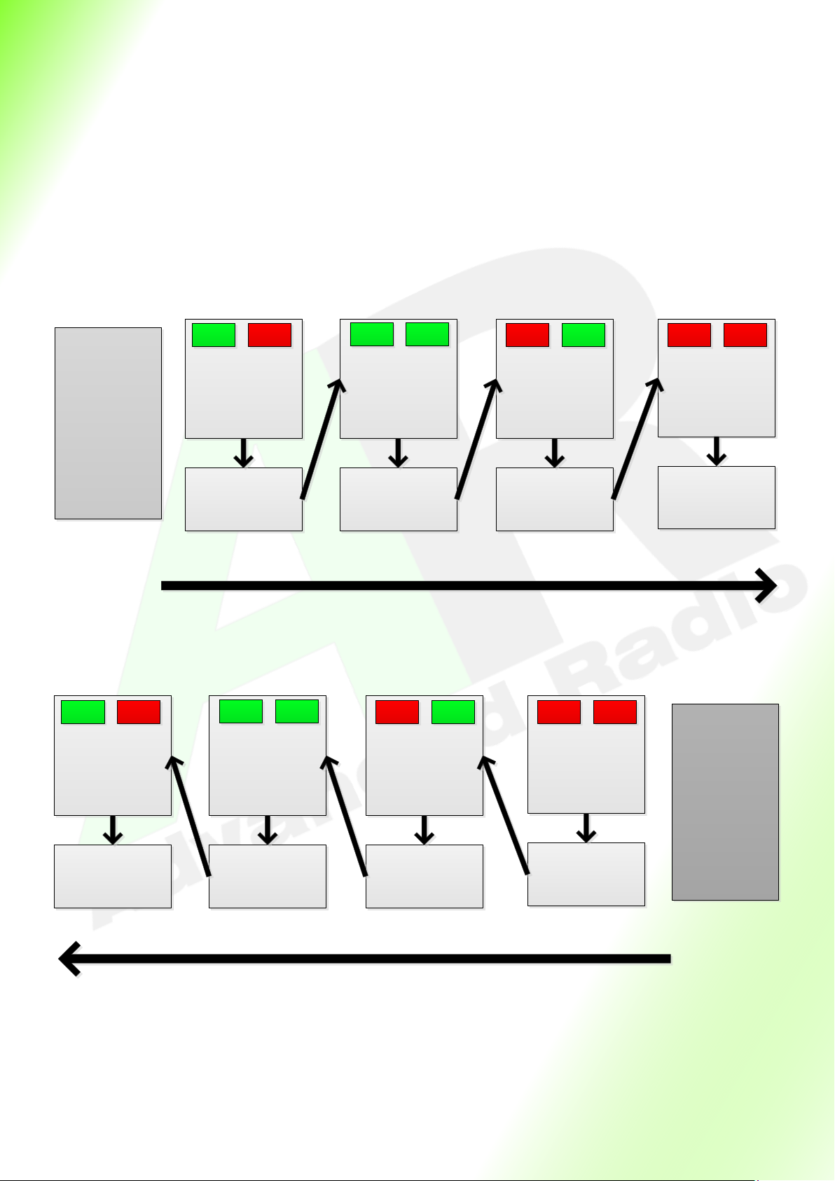
3) Wait Time Step Oset
Sequencing Down to Up—When running the sequencer from the DOWN State to the UP state wait mes
for the CURRENT step are applied .
Sequencing UP to DOWN—When running the sequencer from an UP State to a DOWN state the wait
mes for the current step + 1 are applied.
We hope you enjoy all the power available from the Advanced Radio Air Safe system.
If you have any feedback please feel free to contact us.
The Advanced Radio Engineering Team.
Step = DOWN
Gear is down and door
are are closed
Step = 1
Gear is still down and
doors transition to
open
Wait Time
1.0 Second
for doors to open
Transmitter switch is
switched to Gear
UP position
Step = 2
Gear transitions to up
position and doors
remain open
Wait Time
5.0 Seconds
for gear to transition
Step = UP
Gear is in UP position
and Doors transition
to closed
Wait Time
1.0 Seconds
Gear Doors
Gear Doors Gear Doors Gear Doors
Wait Time
0.0 Seconds
Gear Down To Up Sequence
Step wait times are normal
Transmitter switch is
set to Gear DOWN
position
Step = DOWN
Gear is down and door
transition to closed
Step = 1
Gear transitions to
down and doors
remain open
Wait Time
1.0 Second
for doors to close
Wait Time
5.0 Seconds
for gear to transition
Step = 2
Doors transition to
open position and gear
remains up
Wait Time
1.0 Second for doors to
open
Step = UP
Gear and Doors are in
UP position
Wait Time
0.0 Seconds
Gear Doors
Gear Doors Gear Doors Gear Doors
Step wait times are shifted
Gear Up To Down Sequence

12
Replacement Warranty
At Advanced Radio our products are designed and tested to very high standards. We use only
the highest quality electronic components sourced from reputable manufacturers; ST Micro,
BOSCH, TDK, Linear Technology, Texas Instruments, Cypress Semiconductor Corp and NPX. Our
circuit boards are assembled in Australia in a cered ISO900-2008 and ISO 13485 medical
devices risk management quality assurance environment.
At Advanced Radio we understand the value of the models that run our RC division of
electronics. During our many years of operaon we have focused on and developed a high
quality product and reputable tesng regime. Our QC process has been developed from many
years of experience designing and working in medical systems. We understand completely the
processes involved to achieve a very high quality and reliable product.
Our QC process provides for complete system funconality tesng followed by rigorous load
and stress tesng. If the unit passes this stress test it is further run and heat soaked at 60°C for
a period of 8 hours prior to nal tesng where it is load tested for a second me. If it passes
these tests it is then packaged.
We believe in our processes and so we are oering a 2 year warranty on the Air Safe unit if
found to be defecve in material and/or workmanship when used in the intended purpose.
Shipping charges related to any warranty claim are at the expense of the user, but Advanced
Radio may elect to cover shipping charges at it’s discreon.
Warranty does not cover over voltage or over current damage beyond stated specicaon.
Warranty does not cover damage due to negligence, abuse, accident, improper installaon or
improper mounng.
Warranty does not cover loss of me, inconvenience, loss of model, or other incidental or
consequenal damages.
Table of contents


