Advaning LUXURY Series User manual

For your safety and the safety of others, please read all of the instructions and
warnings in this manual carefully before proceeding with an installation and usage.
LUXURY SERIES
Retractable Awning
Owner’s Manual

1
TABLE OF CONTENTS
Safety instructions and warnings........................................... 2
Package contents and parts .............................................. 4
Tool requirements ...................................................... 5
Awning terminology and location .......................................... 6
Installation
Bracket placement reference chart ................................... 7
Pre-Installation guide (standard) ..................................... 8
Pre-Installation guide (roof mount) ................................... 9
Install wall brackets
Standard stud installation ...................................... 10
Masonry installation ........................................... 12
Install ceiling/soft brackets ....................................... 14
Install awning onto brackets ....................................... 16
Ready your awning............................................... 16
Electric awnings, power cord connection ............................. 17
Electric awnings, prepare your remote control ......................... 17
Operation
Manual operation ................................................ 17
Electric operation................................................ 18
Fabric rolling direction ........................................... 18
Adjust awning pitch .............................................. 19
Maintenance.......................................................... 20
Warranty and customer service ........................................21~22

2
The awning arms contain
tensioned cables. Always
use caution, securely tie
the awnings arms to the
awning when performing
installation, adjustments,
or repairs. Sudden
movement of tension
arms can result in serious
personal injury, product
and/or property damage.
CAUTION
Fig.1
Fig.2
SAFETY INSTRUCTIONS AND WARNINGS
In order to avoid acci-
dental injury or dam-
age, DO NOT remove
arm safety restraints
until instructed.
SAFETY FIRST, PLEASE READ THE FOLLOWING POINTS TO REDUCE THE RISK OF
FIRE, ELECTRIC SHOCK OR PERSONAL INJURY.
Installation
• Pay close attention throughout the installation process to ensure that the Advaning awning is installed properly and
according to the safety guidelines outlined herein.
• Do not attempt installation while under the inuence of alcohol or drug substances.
• Do not remove the safety restraints from the awning’s lateral arms until instructed to do so. The arms contain tensioned
springs and may release very quickly. Always ensure no persons or objects are directly in arm projection path at all
times.
• Do not proceed with an installation if you feel that you cannot properly and safely complete, please seek professional
help.
• Always wear protective gear and gloves when handling sharp metal parts.
• Only perform installation/maintenance/cleaning in dry and optimal weather conditions.
• 2 or more persons are recommended for installation. Installation will require to lift the assembled awning onto the
brackets. Ensure help is available to help lift.
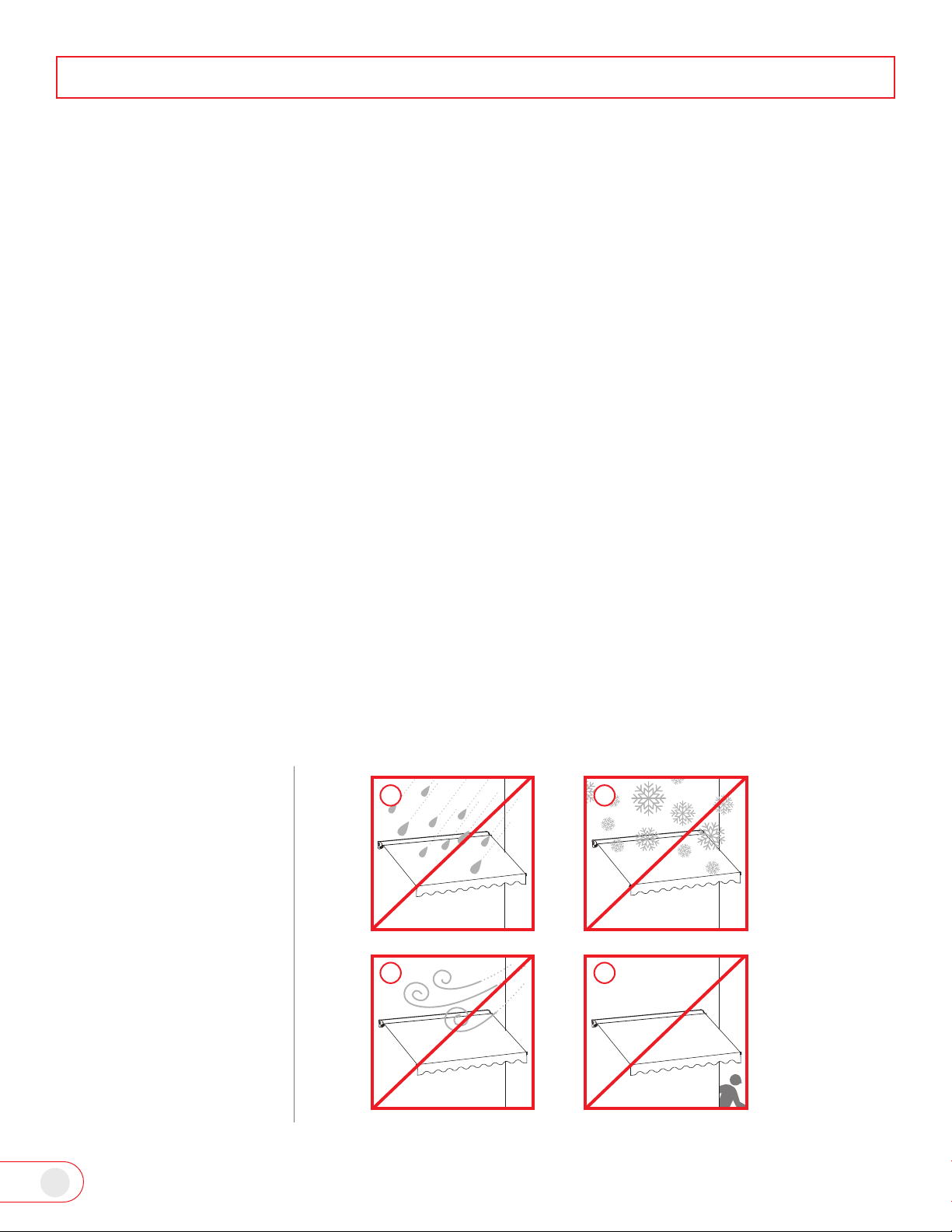
SAFETY INSTRUCTIONS AND WARNINGS
DO NOT keep the awning
open during:
A: RAIN
B: SNOW
C: STRONG WIND
D: UNSUPERVISED
PERIODS
3
Usage
• Only use Advaning recommended accessories and original replacement parts.
• Only perform installation/maintenance/cleaning in dry and optimal weather conditions.
• Do not place any heat source or open ame under or near the awning.
• Do not place, hang, or stand objects or persons on the awning itself. Doing so can damage the awning or cause severe
personal injury and in extreme cases death.
• Do not carry out any maintenance other than what is shown in this manual. For any issues that are not covered in this
• The product should only be operated by an adult that understands all the functions and operations. Please keep unsu-
pervised children away from playing with the awning or its parts.
• The product should be used only as described in this Advaning Owner’s manual.
Electric Awnings Only
• Do not disassemble the awning motor, please seek support from Advaning Customer Service. Email: [email protected].
• Do not handle any part of the power plug or motor with wet hands or objects. Doing so could induce an electric shock.
• Do not use the electric option if the cord or plug is damaged. For damaged power cords and plugs, please seek sup-
• Ensure that the power cord is not strained and that it has ample slack to avoid damage. Avoid pulling the cord around
sharp edges or corners. Keep the power cord away from high trafc areas.
• Do not pull or tug on the cord. Grasp the plug by the base when unplugging the device to avoid damage. Rewind the
cord and store to prevent a tripping hazard.
SAFETY INSTRUCTIONS AND WARNINGS
Fig.3
A B
C D

4
Before attempting your
install, please ensure that the
package contains all parts
and qty’s as listed for your
awning size.
*Motorized models Include:
• 16ft power cord
• Motor Regulator
• Remote Control Kit
-Remote with cover screw
-Battery
-Wall Cradle
-Wall Mount with screws
Advaning’s motorized awnings al-
low users to set a custom stop set-
ting with the Motor Regulator tool.
To safeguard your awnings warran-
ty, we ask that you contact Advan-
ing’s customer support for proper
instructions before attempting any
adjustments. Adjustments without
safeguarding your warranty rst
voids the motors warranty.
If no custom settings are needed,
please save the Motor Regulator
tool with your Owner’s Manual in
case it is needed in the future.
PACKAGE CONTENTS AND PARTS
Fig.5
Optional Roof Mount
Brackets ~ Sold Seperately
Part# ZAW-RM-BRK
Model size 8’~10’ 12’ 14’ 16’
Parts name Quantity
Wall/
ceiling dual
bracket set
Wall/ ceiling
bracket 2 3 4 5
Retaining hex bolt 2 3 4 5
Retaining nut 2 3 4 5
3/8” washer 2 3 4 5
3/8”x4” Lag screw 4 6 8 10
3/8” Flat washer 4 6 8 10
M13 x 4”
Expansion
bolt set
Expansion bolt 4 6 8 10
Washer 4 6 8 10
Hex bolt 4 6 8 10
Assembled Awning Qty: 1
Hand Crank Qty: 1 (63 Inches Length)
Remote Control Kit*
Qty: 1
Fig.6
Fig.4
Motor Regulator*Qty: 1
5
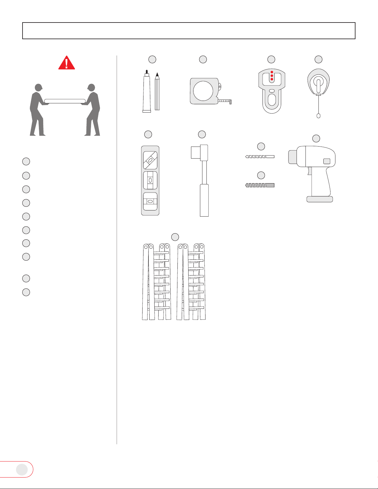
TOOL REQUIREMENTS
Fig.7
Minimum 2 people to install
REQUIRED TOOLS
Marker / pencil
Measuring tape
Electronic Stud nder
Chalk line / laser level
Level
3/8” socket wrench
*Wood Drill Bit
1/2” Masonry Drill Bit
Power Drill / Hammer
Drill (Masonry)
Ladders (2)
*Dependent on wood species:
1/4” ~ 9/32” drill bit.
1
5 6
3
7
2 4
8
9
10
1
5
6
3
7
2
4
8
9
10

6
AWNING TERMINOLOGY AND LOCATION
Arm shoulder
Cassette
Crank loop
Torsion bar
Roller tube
Awning fabric
Front bar
Valance
Powercord
Retractable arms
Easy PitchTM loop
Wall/ceiling bracket
Lag screw
Retaining bolt
Fig.8
Electric model only
1
3
6
7
2
4
5
8
9
10
11
12
13
14
1
6
2
4
5
7
8
12
10
10
13
14
3
11
11
9
7
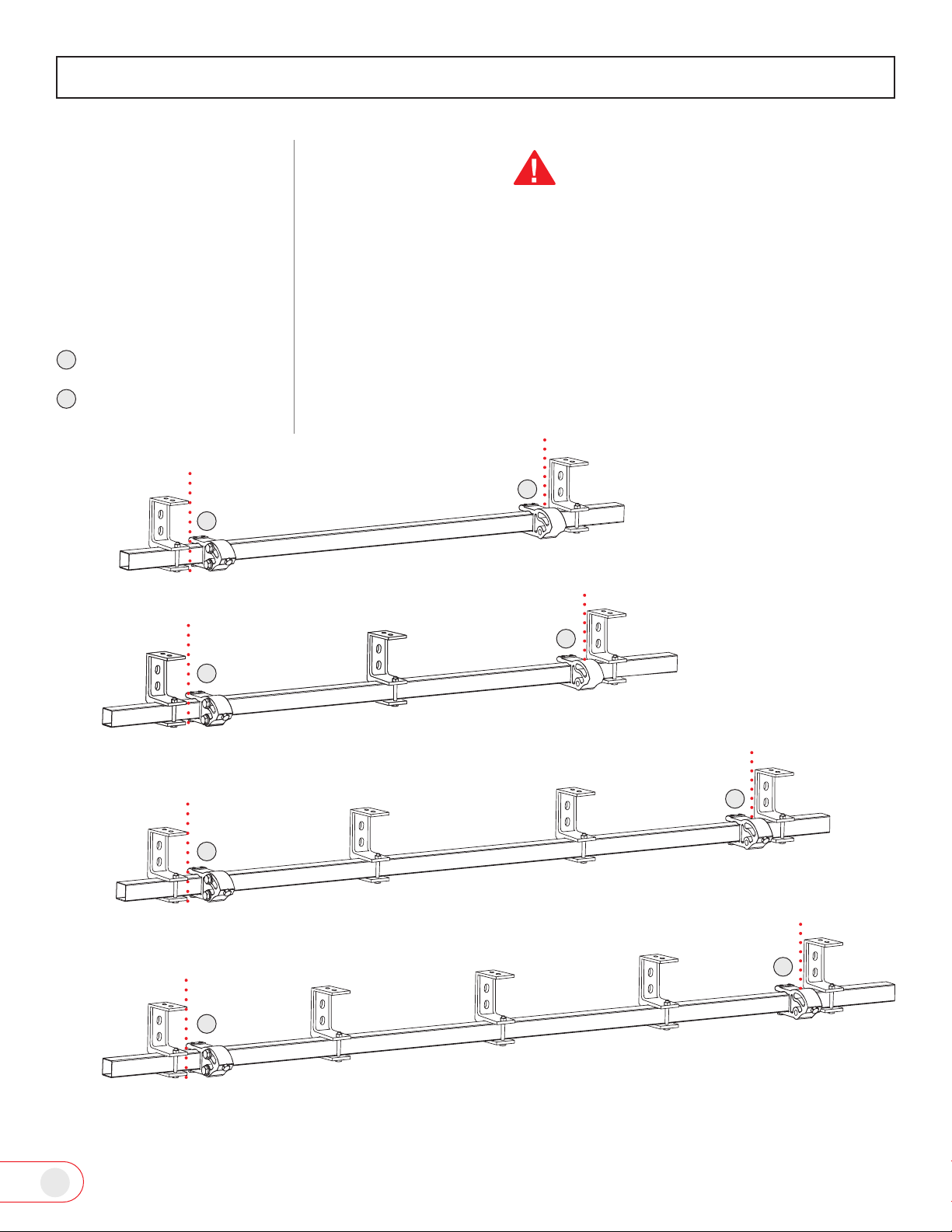
INSTALLATION
Fig.9
Left awning shoulder
Right awning shoulder
BRACKET
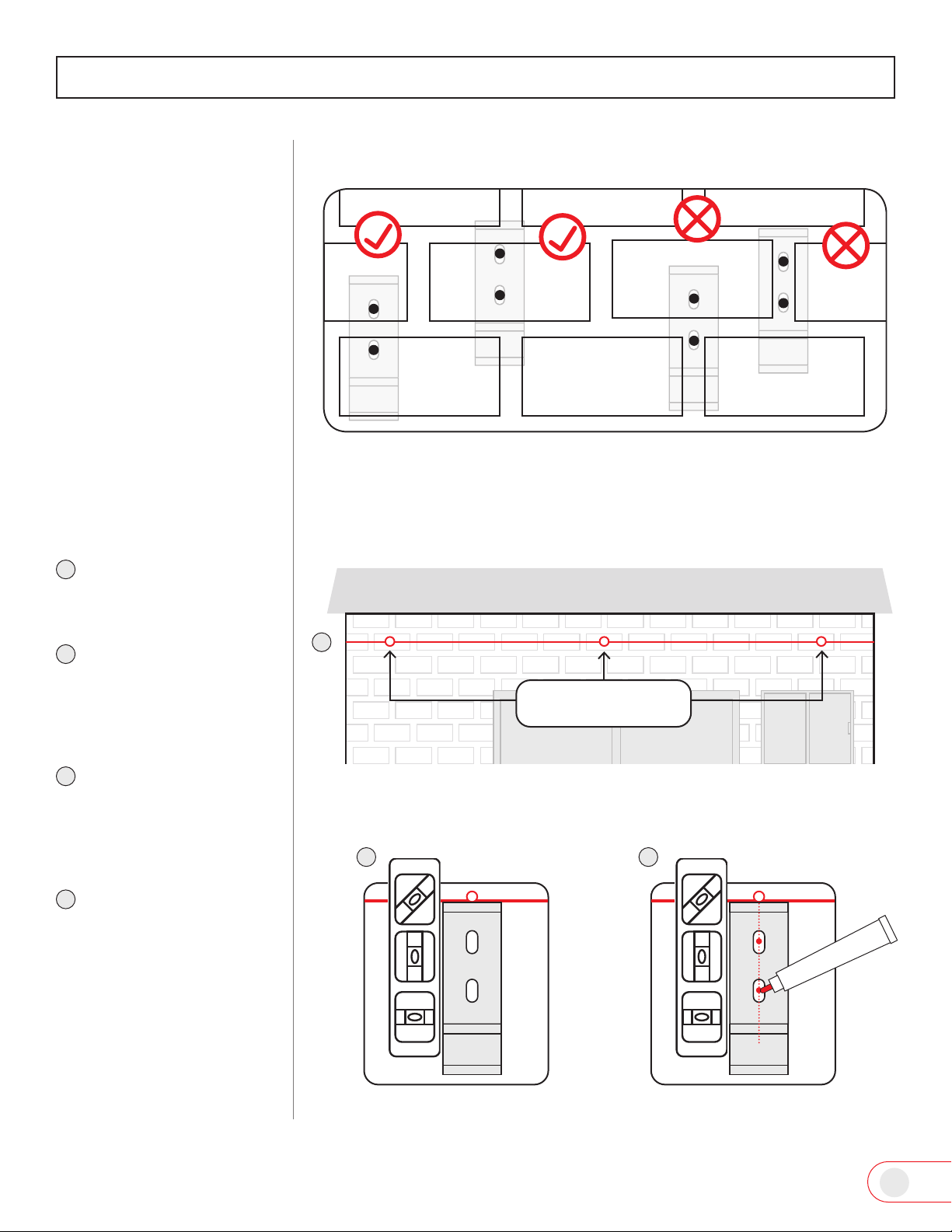
PLACEMENT
REFERENCE CHART
Use the illustrations below
for optimal bracket place-
ment.
IMPORTANT
ALL BRACKETS MUST BE MOUNTED DIRECTLY ONTO WALL STUDS OR
OTHER MAJOR STRUCTURAL SUPPORTS.
FOR OPTIMAL BALANCE OF THE AWNING WEIGHT DISTRIBUTION,
PLEASE ATTEMPT TO FOLLOW THE BRACKET PLACEMENT AS
ILLUSTRATED.
NOTE: NOT EVERY INSTALLATION IS IDENTICAL AND MOST STUDS/
STRUCTURAL SUPPORTS WILL NOT ALWAYS ALIGN, THE BRACKETS MAY
BE MOVED TO BEST SAFELY FIT YOUR SPECIFIC STUD/STRUCTURAL
SUPPORT LOCATION WHILE SUPPORTING THE AWNING ONCE
INSTALLED.
8 ~ 10 feet awning
12 feet awning
14 feet awning
16 feet awning
A
B
A
A
A
A
B
B
B
B

8
INSTALLATION
Fig 11
Fig 10
Locate a position that is
Recommended: 8 to 10 ft.
above the ground/oor,
deck etc.
Recommended (for wall
mounts only): Minimum
of 1 inch clearance below
the roof/eave/overhang
etc.
Critical: Minimum of 10
inches clear vertical run
length (no obstructions)
– depending on awning
size.
Run length should be free
and clear of any obstructions
along the entirety of planned
install site.
Personal & specic structural
physicalities may require de-
viation from the recommend-
ed measurements, consult
with a professional installer
who can best assess your in-
stallation site and ensure a
safe and full function of the
awning once installed.
PRE-INSTALLATION
GUIDE
Side view
Ground, oor or deck
Roof, eave or overhang
10 inches clear space
Ground, oor or deck
Front
Bar
BMinimum 1 inch
Roof, eave or overhang
Recommended
8~10 feet
8 ~ 11 feet projection space
Minimum 1 inch
Minimum 10 inch
clear space
A
Recommended
8~10 feet*
C
A
B
C
9
INSTALLATION
IMPORTANT! Ensure that
you have the sufcient quan-
tity of roof brackets before
proceeding with your instal-
lation.
All Roof Mount Brackets
must be mounted directly to
roof rafters or other major
structural supports.
PRE-INSTALLATION
GUIDE
(ROOF MOUNT)
Locate a placement on roof
that is:
Straight/Level Roof Line -
Parrallel to Level Ground.
Clear of Any Obstruc-
tions for a Minnimum of
12 inches.
Has a Continues Line of
Roof Rafters.
Ensure the spacing allows
for the run length of your
awning.
A
B
C
CAUTION
Gutters may obstruct
access to Awning’s
Open/Close & Tilt
Functions
Install directly
over eaves
section of
roof only.
Install directly onto roof rafter.
Install within 12”
of eave edge
Fig.12
Fig.13
Straight/Level Roof Line
A
B
C
Roof Mount
Sold Seperately

10
INSTALLATION
Fig 14
Fig 15
General stud framing
installation
WALL MOUNT
INSTALLATION
Measure and mark where
the top of your awning
bracket will be placed.
Use a level and chalk line
or laser level to mark
your bracket guide line.
Locate and mark the
center of the wall studs
along this line using a st
ud nder. *Follow your
specic stud nders
manufacturer’s instruc-
tions to properly locate
studs.
Align the top of the
bracket to the chalk line.
Align the center of the
bracket mounting holes
with the center of the
stud.
Stud nder
1Recommended, 1 inch.
Bracket
Center of stud
Level Chalkliner
1
Recommended
8~10 feet
2
3
4
5
1
2
3
4
5

11
Fig 18 Fig 19
Fig 20
INSTALLATION
Use a level to make sure
the bracket is straight
and mark the center of
the mounting holes.
Drill mounting pilot
holes.
Place bracket over pre-
drilled holes and use a
level to ensure the brack-
et is leveled and square
to line.
Use a lag screw and wash-
er to secure the bracket
to your wall/surface, re-
peat for each bracket.
For proper installation of
brackets on uneven surfaces
or siding, use shims or spac-
ers to level the bracket.
Due to a variety of siding
nishes/materials, Advaning
recommends contacting the
siding manufacture for nec-
essary requirements before
using shims, cutting or drill-
ing into your siding.
Fig 16 Fig 17
Level
Washer
Lag screw
Shim/spacer
Siding
Wall
Bracket Bracket
washer
Lag screw
Wall
Level
Wood
3.5”
8
8
9
9
67
Marker/pencil
6
7
12
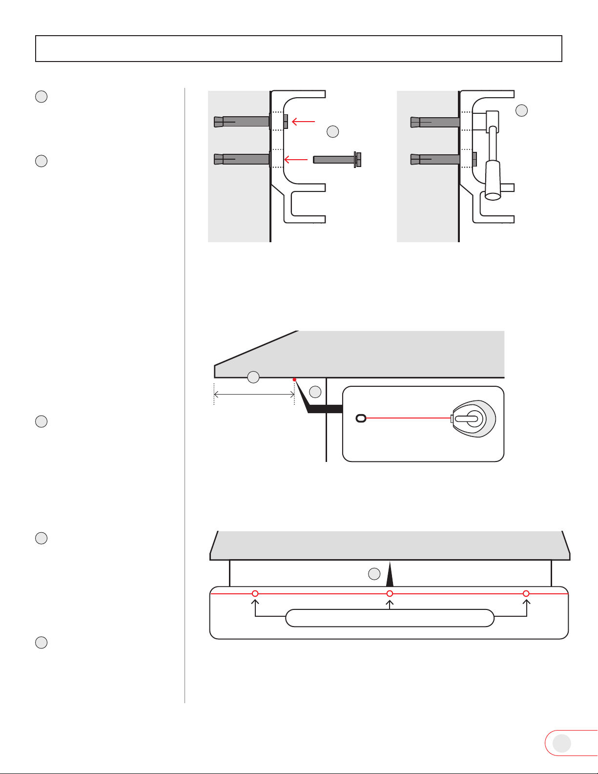
INSTALLATION
Fig 21
Masonry Installation
General (solid) masonry
installation
CAUTION: Brackets must be
installed directly onto solid
brick or concrete.
Avoid severe personal injury
& property damage - Never
install brackets to grout,
mortar or hollow masonry
substrates
Fig 22
Fig 23 Fig 24
Follow instructions for
standard installation step
1 and 2 (page 7).
Use the recommended
bracket location chart
(page 5) to nd bracket
location for your awning
model along the line.
Align the top of the
bracket to the chalk
line and use a level to
make sure the bracket is
straight.
Mark the center of the
bracket mounting holes.
Bracket locations base
on your awning model
Bracket Center
Masonry Installation detailed photos and tips available via www.advaning.com
2
Marker/pencil
3 4
3
4
1
2
13
INSTALLATION
Fig 25
Drill mounting pilot holes.
Insert an expansion
bolt set into each of the
drilled bracket holes.
Leave the hex bolt head
outside of the hole.
Using a socket wrench
tighten the hex bolt, this
will cause the anchor/
wedge to expand and
lock the sleeve in place.
Unscrew and remove
the hex bolt. Ensuring
the sleeve and anchor/
wedge are locked within
the wall.
Place the wall bracket
over the holes and use
a level to make sure the
bracket is straight.
Fig 26
Fig 28 Fig 29
Fig 27
Solid
Masonry
Wall
4 1/8”
Socket
wrench
Level
Expansion bolt set
Hex bolt
Tighten bolt head
Leave hex bolt
head outside
Wall
Wall Bracket
55
6
7
8
9
10
6
7
8
910
14
INSTALLATION
Re-insert the hex bolt
with washer through
bracket and into the xed
sleeve.
Tighten the hex bolts to
secure wall bracket to
surface.
Fig 31
Fig 30
Fig 32
Fig 33
SOFFIT/CEILING
INSTALLATION
Locate a main structural
support (ex: stud/truss),
straight at and leveled
edge of your roof, eave
or overhang that is clear
and free of obstructions.
Using a chalk line or la-
ser level, mark a line that
runs the entire length of
your awning. The awning
will stand 10” off of this
line.
Use the recommended
bracket location chart
(page 5) to determine
bracket locations for your
awning model along the
line.
General wood framing
installation
Tighten
BracketBracket
Hex bolt
Wall Wall
Masonry Installation detailed photos and tips available via www.advaning.com
Roof, eave or overhang
Chalkliner
Minimum 10 inch
clear space
Roof, eave or overhang
Bracket locations base on your awning model
11
12
11
12
1
2
3
1
2
3

15
INSTALLATION
Fig 34 Fig 35
Place the soft/ceiling
mount side of bracket in
place, use a level to en-
sure bracket is straight
and mark the center of
the mounting holes.
Drill mounting holes.
Place bracket over the
pre-drilled holes and
use a level to ensure the
backet is square to line.
Use a lag screw and wash-
er to secure the bracket
to your soft/ceiling, re-
peat for each bracket.
Fig 36 Fig 37
Washer
Lag screw
Bracket Bracket
67
45
Level
Bracket
3.5”
Marker/pencil
4
5
6
7

16
INSTALLATION
Fig 38
Fig 39
INSTALLING AWNING
ONTO BRACKETS
Remove the retaining
bolts from each bracket.
Lift and slide the awning
to brackets and slide
the torsion bar into the
bracket fork.
Insert the retaining bolt
and washer into the
bracket fork holes and
secure with nut.
Securely tighten the bolts
with a socket wrench.
CAUTION: The arms contain
tensioned springs and may
release very quickly.
Before removing the safety
restraints, make sure that no
persons or objects are direct-
ly in arm projection path.
Motorized Awning: Do not
plug in the power cord at this
step.
READY YOUR
AWNING
Position yourself un-
der the awning.
With scissors, care-
fully cut the safety
restraints from the
arms one at a time.
Avoid damaging your
awning – Do not use
a knife or blade.
Fig 41
Fig 40
Socket wrench
Washer
Retaining
bolt
Nut
Torsion bar
1
1
22
3
3
4
4
1
2
1
2

17
CR2430
Battery
INSTALLATION
OPERATION
Fig 43
Fig 42
2
2
Plug into a GFI rated
outdoor socket.
Use a drip loop to
avoid water collecting
on electrical socket.
ELECTRIC AWNINGS
1
1
2
2
PREPARE REMOTE
CONTROL
Your remote control will
come with a CR2430 Battery.
Genlty pull the plastic tab so
that your battery makes con-
nection.
Note: Additional remote in-
formation in Maintenance
Section, Page 16
Ensure the batteries
(+) symbol faces out-
ward.
Replace the battery
cover and secure
with screw.
Power cord connection
Note: Never modify the cord
or plug.
Fig 44
Use the hand crank to
open the awning fully
then close it completely
to test for proper
operation.
Use the hand crank and
open the awning to
desired extension.
MANUAL OPERATION
To keep the fabric taut, al-
ways reserve a small portion
of the awning fabric on the
roller tube
Correct rolling instruc-tions:
Page 15, Fig 41.
OPENCLOSE
Drip
loop
Battery
cover
Arms will not
fully straighten
when extended
1
1
1
1
2
2

18
OPERATION
Fig 45
Use the remote control to
deploy (open) the awning
fully then use the remote
control to retract (close)
the awning completely.
Use the remote control’s
stop button (center) to
stop the awning at a de-
sired extension.
Note: Additional remote in-
formation in Maintenance
Section, Page 16
REMOTE CONTROL
OPERATION –
MOTORIZED
AWNINGS ONLY
1 2
FABRIC ROLLING
DIRECTION
Always ensure the fabric is
rolled over the fabric roller
tube.
Fig 46
CORRECT
INCORRECT
Fabric
Fabric
Remote
control
1
2

19
Fabric Fabric
Fabric
OPERATION
Fig 48
Fig 49
Fig 47
Note: If pitch is adjusted up-
wards above the factory set-
ting of 15 degrees, we rec-
ommend lowering the pitch
down to properly close the
awning.
Open the awning about
1/3 extension or 2ft out.
With the aid of a helper
supporting the front bar
of the awning, hook the
hand crank through one
of the Easy Pitch™ loops.
Turn the hand crank to
adjust the awnings pitch
up or down.
Repeat the adjustment to
all Easy Pitch™ loops.
Fully open the awning
and with the use of a lev-
el ensure the front bar is
straight and leveled.
ADJUST AWNING
PITCH
EXTEND OUT 1/3 OR 2FT MAKE ADJUSTMENT UP OR DOWN
EXAMPLE OF LOWERED PITCH
EXTEND OUT FULLY
Front bar
8-16ft awning: 2 Easy PitchTM loops
2
2
3
1
2
3
4
51 32 4
5
Other manuals for LUXURY Series
2
Table of contents
Popular Lawn And Garden Equipment manuals by other brands

Sunforce
Sunforce SOLAR user manual

GARDEN OF EDEN
GARDEN OF EDEN 55627 user manual

Goizper Group
Goizper Group MATABI POLMINOR instruction manual

Rain Bird
Rain Bird 11000 Series Operation & maintenance manual

Cub Cadet
Cub Cadet BB 230 brochure

EXTOL PREMIUM
EXTOL PREMIUM 8891590 Translation of the original user manual


Vertex
Vertex 1/3 HP Maintenance instructions

GHE
GHE AeroFlo 80 manual

Land Pride
Land Pride Post Hole Diggers HD25 Operator's manual

Yazoo/Kees
Yazoo/Kees Z9 Commercial Collection System Z9A Operator's & parts manual

Premier designs
Premier designs WindGarden 26829 Assembly instructions

Snapper
Snapper 1691351 installation instructions