Advantech B+B SmartWorx McBasic TX User manual

McBasic TX/FX
USER MANUAL

McBasic TX/FX
ii
Advantech B+B SmartWorx - Americas
707 Dayton Road
Ottawa, IL 61350 USA
Phone 1 (815) 433-5100
Fax 1 (815) 433-5105
Advantech B+B SmartWorx - Europe
Westlink Commercial Park
Oranmore, Co. Galway, Ireland
Phone +353 91-792444
Fax +353 91-792445
www.advantech-bb.com
support@advantech-bb.com

McBasic TX/FX
ii
CONTENTS
About McBasic TX/FX ............................................................................... 4
Installing McBAsic TX/FX ............................................................................................... 4
Configuring McBasic TX/FX ........................................................................................... 4
Auto Negotiation on McBasic TX/FX ............................................................................. 5
About FiberAlert & LinkLoss...................................................................... 7
FiberAlert and LinkLoss .................................................................................................8
Auto Negotiation on McBasic TX/FX ........................................................ 10
LED Operation ....................................................................................... 11
Troubleshooting - Installation .................................................................. 12
Specifications......................................................................................... 13
B+B SmartWorx Technical Support.......................................................... 14
Statements, Precautions, Guidelines, Regulatory ..................................... 14
FCC Radio Frequency Interference Statement....................................................... 14
Electrostatic Discharge (ESD) Precautions ..................................................................15
Fiber Optic Cleaning Guidelines......................................................................... 15
Regulatory, Standards, Compliances ....................................................... 16

McBasic TX/FX
4
ABOUT MCBASIC TX/FX
McBasic TX/FX is an IEEE 802.3 media converter that performs a single
conversion between 100Base-TX twisted-pair and 100Base-FX multi-mode or
single-mode fiber. Single-strand fiber versions are also available. The unit
includes one RJ-45 connector for the twisted-pair port and either ST, SC, MT or
LC connectors for the fiber port. McBasic TX/FX is a 1U high, standalone unit
that includes diagnostic LEDs for each port and a universal (100/240 VAC)
power supply.
NOTE: All versions of the 100 Mbps Fast Ethernet McBasic media converter, including
850 nm multi-mode fiber (TX/SX) and single-strand versions (TX/SSFX), will be referred
to as McBasic TX/FX throughout this manual except where differences must be
indicated.
NOTE: Some options require items that are sold separately, available from B+B
SmartWorx.
INSTALLING MCBASIC TX/FX
McBasic TX/FX comes ready to install; make all configurations after installation.
To install McBasic TX/FX, first make sure that the unit is placed on a suitable
flat surface. Attach the cables between the McBasic TX/FX and each device
that will be interconnected; then plug the unit into a reliable, filtered power
source.
NOTE
: INSTALLATION TIP - Since single-strand fiber products use optics that transmit and receive
on two different wavelengths, single-strand fiber products must be deployed in pairs, or connect two
compatible B+B SmartWorx single-strand fiber products. The two connected products must also have
the same speed and distance capabilities (i.e. both are single-mode [20km] or both are single/PLUS
[40km]).
CONFIGURING MCBASIC TX/FX
McBasic TX/FX features an 8-position DIP
Switch for configuring the unit after
installation. Access this switch through a cut-
out in the bottom of the unit. After configuring
the DIP Switch, power down the unit and then
power up again for changes to take effect.
Default settings for the following features are
shown at right.

McBasic TX/FX
5
AUTO NEGOTIATION ON MCBASIC TX/FX
McBasic TX/FX includes Auto Negotiation. When Auto Negotiation is enabled
(default), the media converter negotiates as a 100 Mbps Full-Duplex device. If
the device the McBasic TX/FX is connected to can operate at 100 Mbps Full-
Duplex, a link will be established.
If the twisted-pair port on the other device does not have the ability to Auto
Negotiate, or if a 100 Mbps Half-Duplex connection is desired, Auto Negotiation
on McBasic TX/FX must be disabled. Half- and Full-Duplex settings must be
manually set and match on both devices to which McBasic TX/FX is connected.
The diagram below shows a typical application, followed by a table with three
possible configurations:
HDX
--------------------------
OK (Manual Setting Only)
---------------------------
HDX
FDX
----------------------------
OK (Auto/Manual Setting)
--------------------------
HDX
HDX
-------------------------------------
WRONG
--------------------------------------
FDX
End to End Connection
Switch
TX/FX
Half-Duplex
Manually Configure HDX
Auto Negotiation Off
Full-Duplex
Manually Configure FDX
Auto Negotiation Off
Full-Duplex
Auto Negotiation
On
Auto Negotiation
On
Switch
Media
Media
Switch

McBasic TX/FX
6
Twisted-pair Crossover/Pass-Through Connections
Whether using crossover or straight-through CAT5 twisted-pair cabling,
McBasic TX/FX will support both types of connections by one of the following
methods:
DSW#1 Auto Negotiation (AN)
If set to default ON, the media converter will
negotiate with the link partner to the speed
and duplex mode. If set to OFF, FORCE
mode is available, and the link partner must
be set to FORCE mode as well.
DSW#2 (reserved)
DSW#3 MDI/MDIX To manually configure McBasic TX/FX for a
pass-through (MDI) or crossover (MDI-X)
connection, move the Auto MDI/MDI-X
Switch 4 to OFF; then move Switch 3 to the
desired connection type: MDI=OFF and
MDI-X=ON. If unsure of the type of
connection, set the DIP Switch to a position
that makes the twisted-pair LNK (link) LED
glow.
DSW#4 Auto MDI/MDIX McBasic TX/FX includes AutoCross, a
feature that automatically selects between a
crossover workstation or pass-through
connection, depending on the connected
device. To enable AutoCross, move the
Auto MDI/MDI-X switch to the ON position.
DSW#5 TXLL TX LinkLoss - diagnostic feature to
troubleshoot a loss on the copper port.
DSW#6 FX LL FX LinkLoss - a diagnostic feature to
troubleshoot a loss on the fiber port.
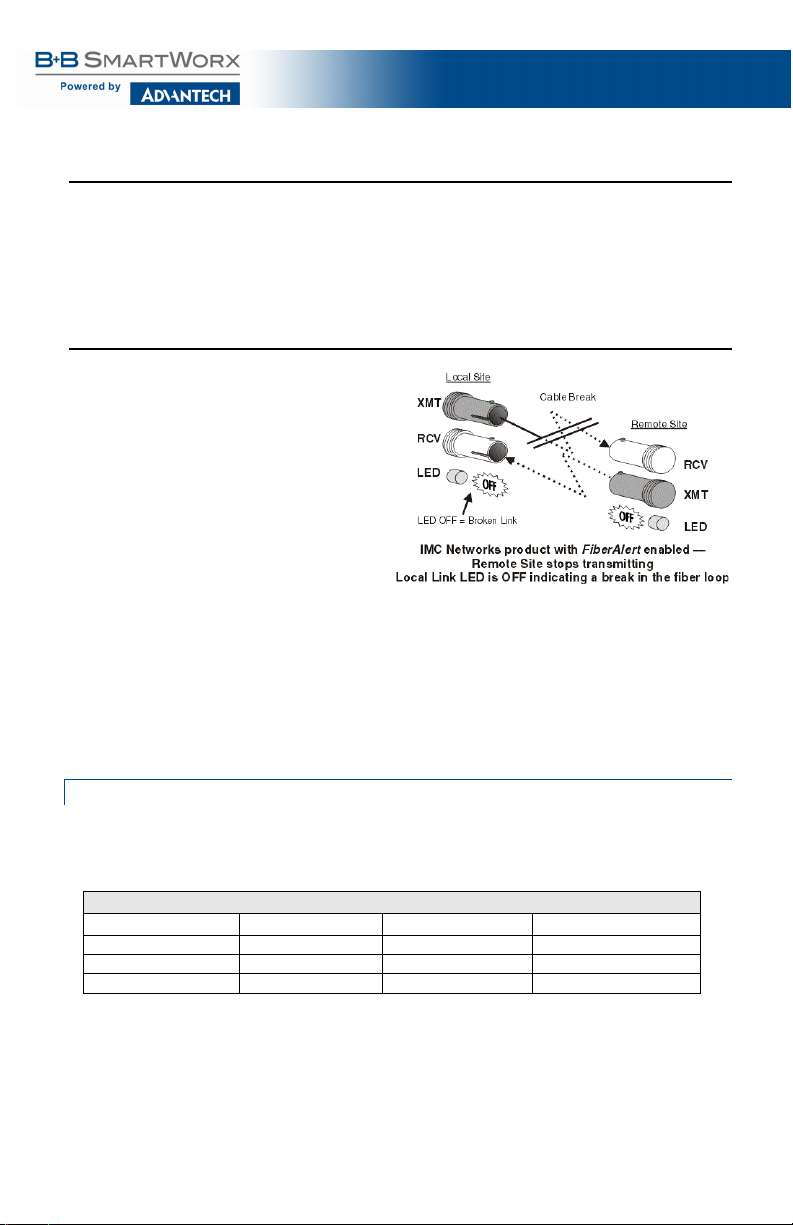
DSW#7 FA FiberAlert - a diagnostic feature to
troubleshoot the loss of one strand of fiber.
DSW#8 FA Pulse Pulsing FA - a diagnostic feature to
troubleshoot the loss of one strand of fiber;
Pulse FA can be enabled on both media
converters.

McBasic TX/FX
7
ABOUT FIBERALERT & LINKLOSS
McBasic TX/FX comes with the following troubleshooting features:
•
FX LinkLoss (a.k.a. "Fiber LinkLoss" or "LinkLoss")
•
TX LinkLoss (a.k.a. "Twisted-pair LinkLoss” or "Reverse LinkLoss”)
•
FiberAlert (including Pulsing FiberAlert)
LinkLoss and FiberAlert are advanced troubleshooting features that can help
locate "silent failures" on the network. However, it is vital to understand exactly
how FiberAlert and LinkLoss work, and how they will react in the network
configuration, before attempting to install the enclosed module(s).
**WARNING**
Installing modules without understanding the effects of LinkLoss and FiberAlert can cause perfectly
functioning units to appear flawed or even non-functional.
Link Integrity
During normal operation, link integrity pulses are transmitted by all point-to-
point Ethernet devices. When an B+B SmartWorx media converter receives
valid link pulses, it knows that the device to which it is connected is up and
sending pulses, and that the copper or fiber cable coming from that device is
intact. The appropriate “LINK” LED is lit to indicate this. The B+B SmartWorx
media converter also sends out link pulses from its copper and fiber
transmitters, but normally has no way of knowing whether the cable to the other
device is intact and the link pulses are reaching the other end. FiberAlert and
LinkLoss allow this information to be obtained from the fiber, even when
physical access to a remote device (and its link integrity LED) is not available.
LinkLoss
FX LinkLoss is a troubleshooting feature. When a fault occurs on the fiber
segment of a conversion, FX LinkLoss detects the fault and passes this
information to the twisted-pair segment. If a media converter is not receiving a
fiber link, FX LinkLoss disables the transmitter on the media converter's
twisted-pair port. This results in a loss of link on the device connected to the
twisted-pair port.

McBasic TX/FX
8
TX LinkLoss
TX LinkLoss is a troubleshooting feature. When a fault occurs on the twisted-
pair segment of a conversion, TX LinkLoss detects the fault and passes the
information to the fiber segment. If a media converter is not receiving a twisted-
pair link, TX LinkLoss disables the transmitter on the media converter's fiber
port. This results in a loss of link on the device connected to the fiber port.
FiberAlert
FiberAlert minimizes problems
associated with the loss of one
strand of fiber. If a strand is
unavailable, the B+B device at
the receiver end notes the loss
of link. The device will stop
transmitting data and the link
signal until a signal or link pulse
is received. The result is that
the link LED on BOTH sides of
the fiber connection will go out,
indicating a fault somewhere in
the fiber loop. Using FiberAlert,
a local site administrator is
notified of a fault and can
quickly determine where a cable
fault is located.
FIBERALERT AND LINKLOSS
The following table provides an overview of the troubleshooting features, their
functionality and the recommended settings for a pair of media converters in a
typical central/main site to remote site application:
LINKLOSS/FIBERALERT COMPARISON TABLE
Feature
Fault Location
Disabled LEDs
Enable At:
FX LinkLoss
Fiber
Twisted-pair
Main Site Only
TX LinkLoss
Twisted-pair
Fiber
Remote Site Only
FiberAlert
Fiber
Fiber
Remote Site Only
NOTE
: INSTALLATION TIP -
Enable FiberAlert on only ONE side of a media conversion; enabling it on both sides will
keep both transmitters off indefinitely. To enable FiberAlert on BOTH sides of the conversion, Pulsing FiberAlert on one unit
must also be enabled. B+B SmartWorx recommends enabling Pulsing FiberAlert on ONE side.
NOTE
:
FiberAlert is not available/applicable on single-strand fiber versions of McBasic.

McBasic TX/FX
9
Pulsing FiberAlert
Use Pulsing FiberAlert in the following two situations:
1. When connecting two McBasic TX/FX units (or McLIM TX/FX modules) with FiberAlert
enabled.
2. When connecting one McBasic TX/FX with FiberAlert enabled and one McBasic
10/100 unit with Link Fault Detection (LFD) enabled.
NOTE
:
Pulsing FiberAlert may be useful when connecting McBasic TX/FX to another manufacturer’s product that has a
similar feature to FiberAlert. Please refer to the McBasic 10/100 Installation Guide for more information on LFD.
Converter 1
Converter 2
FiberAlert Enabled
FiberAlert and Pulsing Fiber/Alert Enabled
FiberAlert Enabled
FiberAlert Disabled
NOTE
:
Pulsing - if unsure of how best to implement these features in the configuration, please contact B+B SmartWorx
Technical Support.

McBasic TX/FX
10
AUTO NEGOTIATION ON MCBASIC TX/FX
McBasic TX/FX includes Auto Negotiation. When Auto Negotiation is enabled
(default), the media converter negotiates as a 100 Mbps Full-Duplex device; if
the device the McBasic TX/FX is connected to can operate at 100 Mbps Full-
Duplex, a link will be established.
If the twisted-pair port on the other device does not have the ability to Auto
Negotiate, or if a 100 Mbps Half-Duplex connection is desired, Auto Negotiation
on McBasic TX/FX must be disabled. Half- and Full-Duplex settings must be
manually set and match on both devices to which McBasic TX/FX is connected.
The diagram below shows a typical application, followed by a table with three
possible configurations.
HDX
--------------------------
OK (Manual Setting Only)
---------------------------
HDX
FDX
----------------------------
OK (Auto/Manual Setting)
--------------------------
HDX
HDX
-------------------------------------
WRONG
--------------------------------------
FDX
End to End Connection
Switch
TX/FX
Half-Duplex
Manually Configure HDX
Auto Negotiation Off
Full-Duplex
Manually Configure FDX
Auto Negotiation Off
Full-Duplex
Auto Negotiation
On
Auto Negotiation
On
Switch
Media
Media
Switch

McBasic TX/FX
11
LED OPERATION
McBasic TX/FX features four diagnostic LEDs. The diagram below shows the
location of the unit’s LEDs. Connect the DC power source.
The LED functions are:
FX RCV
Glows yellow when module is receiving data.
TX LNK
Glows green when a twisted-pair link is established.
FA
Glows green when FiberAlert is enabled. Blinks green when a FiberAlert
situation occurs (i.e. the loss of one strand of fiber).
FX LNK
Glows green when a fiber link is established.

McBasic TX/FX
12
TROUBLESHOOTING - INSTALLATION
•
During installation, first test the fiber and twisted-pair connections with all
troubleshooting features disabled; then enable features, if desired, just before final
installation. This will reduce the features’ interference with testing.
•
When working with units where the features cannot be disabled, BOTH the twisted-
pair and fiber connections must be established before the link LEDs will light.
•
To test a media converter by itself, have an appropriate fiber patch cable, then follow
these steps to test:
Step 1
Connect the media converter to the twisted-pair device with a
twisted-pair cable.
Step 2
Loop a single strand of fiber from the Transmit port to the
Receive port of the media converter.
Step 3
Verify that both twisted-pair and fiber link (see LED Operation)
are on the media converter.
•
Make sure to use the appropriate twisted-pair cable, and have the crossover/pass-
through switch set correctly, if the media converter does not include AutoCross.
•
If using a high powered device (which is designed for long distance installations) for a
short distance installation, the fiber transmitters may overdrive the receivers and cause
data loss. If this is the case, an optical attenuator may be need to be added to the
connection.

McBasic TX/FX
13
SPECIFICATIONS
Power Consumption
(typical)
AC Input Load
100-240VAC ±10%, 50/60 Hz, 1A
Heat generated
51 BTU/hr.
Operating Temperature
0 to +50 °C (+3 to +122 °F)
Storage Temperature
-25 to +85 °C (-13 to +185 °F)
Humidity
5 - 95% (non-condensing)
Dimensions
4.17H x 12.07W x 12.5D7 cm (1.64H x 4.75W x 4.95D in)

McBasic TX/FX
14
B+B SMARTWORX TECHNICAL SUPPORT
USA/Canada: 1 (800) 346-3119 (Ottawa IL USA)
Europe: +353 91 792444 (Ireland / Europe)
Email: support@advantech-bb.com
Web: www.advantech-bb.com
STATEMENTS, PRECAUTIONS, GUIDELINES, RE GULATORY
FCC RADIO FREQUENCY INTERFERENCE STATEMENT
This equipment has been tested and found to comply with the limits for a Class
A computing device, pursuant to Part 15 of the FCC Rules. These limits are
designed to provide reasonable protection against harmful interference when
the equipment is operated in a commercial environment. This equipment
generates, uses and can radiate radio frequency energy and, if not installed
and used in accordance with the instruction manual, may cause harmful
interference to radio communications. Operation of this equipment in a
residential area is likely to cause harmful interference in which the user will be
required to correct the interference at his own expense.
Any changes or modifications not expressly approved by the manufacturer
could void the user’s authority to operate the equipment.
The use of non-shielded I/O cables may not guarantee compliance with FCC
RFI limits. This digital apparatus does not exceed the Class A limits for radio
noise emission from digital apparatus set out in the Radio Interference
Regulation of the Canadian Department of Communications.
Le présent appareil numérique n’émet pas de bruits radioélectriques dépassant
les limites applicables aux appareils numériques de classe A prescrites dans le
Règlement sur le brouillage radioélectrique publié par le ministère des
Communications du Canada.

McBasic TX/FX
15
ELECTROSTATIC DISCHARGE (ESD) PRECAUTIONS
Electrostatic discharge (ESD) can cause damage to any product, add-in modules or stand
alone units, containing electronic components. Always observe the following precautions
when installing or handling these kinds of products.
1. Do not remove unit from its protective packaging until ready to install.
2. Wear an ESD wrist grounding strap before handling any module or component. If the
wrist strap is not available, maintain grounded contact with the system unit throughout
any procedure requiring ESD protection.
3. Hold units by the edges; do not touch the electronic components or gold connectors.
4. After removal, always place boards on a grounded, static-free surface, ESD pad or in
a proper ESD bag. Do not slide the modules or stand-alone units over any surface.
WARNING! Integrated circuits and fiber optic
components are
extremely susceptible to
electrostatic discharge damage. Do not
handle
these components directly unless you are a qualified
service technician and use tools and techniques that
conform to
accepted industry practices.
FIBER OPTIC CLEANING GUIDELINES
Fiber Optic transmitters and receivers are extremely susceptible to
contamination by particles of dirt or dust, which can obstruct the optic path and
cause performance degradation. Good system performance requires clean
optics and connector ferrules.
1. Use fiber patch cords (or connectors, if you terminate your own fiber)
only from a reputable supplier; low-quality components can cause many
hard-to-diagnose problems in an installation.
2. Dust caps are installed at the factory to ensure factory-clean optical
devices. These protective caps should not be removed until the moment
of connecting the fiber cable to the device. Should it be necessary to
disconnect the fiber device, reinstall the protective dust caps.
3. Store spare caps in a dust-free environment such as a sealed plastic bag
or box so that, when reinstalled, they do not introduce any contamination
to the optics.
4. If you suspect that the optics have been contaminated, alternate between
blasting with clean, dry, compressed air and flushing with methanol to
remove particles of dirt.

McBasic TX/FX
16
REGULATORY, STANDARDS, COMPLIANCES
UL/cUL: Listed to Safety of Information Technology Equipment, including Electrical
Business Equipment.
CE: The products described herein comply with the Council Directive on
Electromagnetic Compatibility (2004/108/EC) and the Council Directive on
Electrical Equipment Designed for use within Certain Voltage Limits
(2006/95/EC). Certified to Safety of Information Technology Equipment,
Including Electrical Business Equipment. For further details, contact B+B
SmartWorx.
European Directive 2002/96/EC (WEEE) requires that any equipment that bears
this symbol on product or packaging must not be disposed of with unsorted
municipal waste. This symbol indicates that the equipment should be disposed
of separately from regular household waste. It is the consumer’s responsibility to
dispose of this and all equipment so marked through designated collection
facilities appointed by government or local authorities. Following these steps
through proper disposal and recycling will help prevent potential negative
consequences to the environment and human health. For more detailed
information about proper disposal, please contact local authorities, waste
disposal services, or the point of purchase for this equipment.
© 2018 B+B SmartWorx – powered by Advantech. All rights reserved. The information in this
document is subject to change without notice. B+B SmartWorx assumes no responsibility for any
errors that may appear in this document. McBasic is a trademark of B+B SmartWorx. Other
brands or product names may be trademarks and are the property of their respective companies.
Documentation Number: McBasic_4618m
This manual suits for next models
1
Table of contents
Popular Media Converter manuals by other brands

PCB Piezotronics
PCB Piezotronics 8162-051A Installation and operating manual

Siqura
Siqura Dual Rate SFP Media Converter quick start guide

Goobay
Goobay CAT 5 user manual

Lantronix
Lantronix 4110 Series Cli reference manual

HEIDENHAIN
HEIDENHAIN ECN 1113 Mounting instructions

Solid State Logic
Solid State Logic Alpha-Link AX user guide