Genesis Automation moTrona LW217 User manual

control – motion – interface
LW21702b_e.doc / Feb-14 Page 1 / 12
LW217 – LW218
Optical fibre modules for transmission of SSI encoder
or sensor signals
Transmitter
-
M
odul
e
Modul
e
typ
e
Input level
Power Supply
LW217
Transmitter
RS422
5 V
DC
(± 5
%)
LW217
-
1
Transmitter
RS422
10
–
30
VDC
Receiver Module
Modul
e
typ
e
O
utput level
Power supply
LW218
Receiver
RS422
5
VDC
(± 5
%)
LW218
-
1
Receiver
RS422
10
–
30
VDC
Operating instructions

LW21702b_e.doc / Feb-14 Page 2 / 12
Safety Instructions
This manual is an essential part of the unit and contains important hints about
function, correct handling and commissioning. Non-observance can result in
damage to the unit or the machine or even in injury to persons using the
equipment!
The unit must only be installed, connected and activated by a qualified electrician
It is a must to observe all general and also all country-specific and application-
specific safety standards
When this unit is used with applications where failure or maloperation could cause
damage to a machine or hazard to the operating staff, it is indispensable to meet
effective precautions in order to avoid such consequences
Regarding installation, wiring, environmental conditions, screening of cables and
earthing, you must follow the general standards of industrial automation industry
- Errors and omissions excepted –
General instructions for cabling, screening and grounding can be found in the
SUPPORT section of our website http://www.motrona.com
Version:
Description
LW21701a/pp/02
_2012
First edition
LW21701b/pp/11_2012
Small change
LW21702a/pp/nw/08_13
Adjustment due
to a new device generation
LW
21702b/tj/nw/02_14
Adjustment of
p
in
a
ssignment LW218

LW21702b_e.doc / Feb-14 Page 3 / 12
Table of Contents
1. Description .................................................................................................. 4
2. Electrical and optical connections................................................................ 5
2.1. Pin Assignment LW217 (transmitter) ....................................................................5
2.2. Pin Assignment LW218 (receiver) .........................................................................6
2.3. Electrical connections ...........................................................................................7
2.4. Optical connections...............................................................................................8
3. Operation and LED-function......................................................................... 8
3.1. LW217 (transmitter) ..............................................................................................8
3.2. LW218 (receiver) .................................................................................................10
4. Dimensions and technical characteristics .................................................. 11
4.1. Dimension drawing: ............................................................................................11
4.2. Technical characteristics.....................................................................................12

LW21702b_e.doc / Feb-14 Page 4 / 12
1. Description
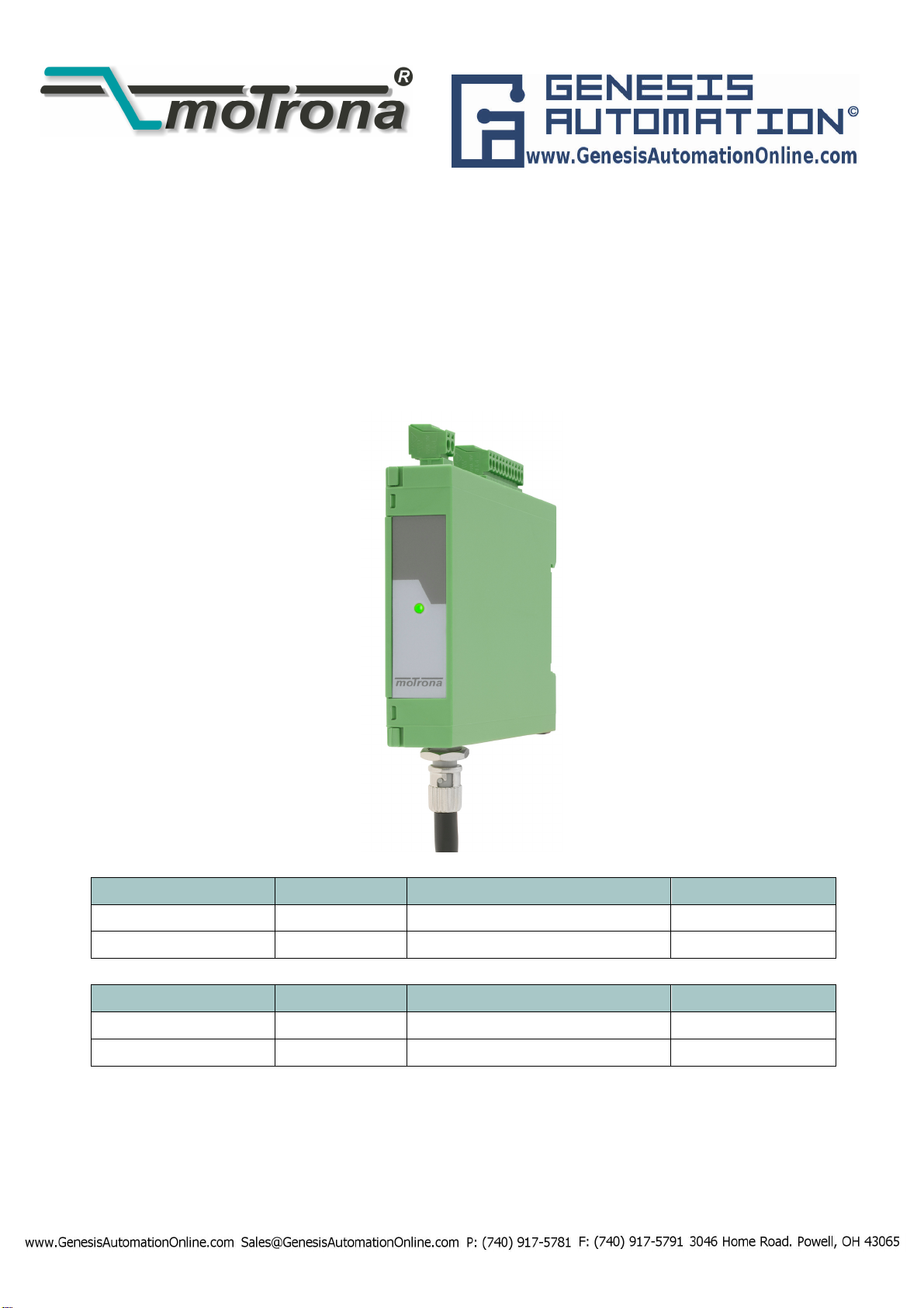
The optical fibre modules LW217 and LW218 form together a transmission system for data
transmission of industrial signals by means of optical fibres.
The system is made of an optical fibre transmitter and of an optical fibre receiver.
The optical fibre transmitter module converts the electrical data of a usual sensor or encoder
equipped with a synchronous serial interface (SSI) into optical fibre signals.
The optical fibre receiver module converts the optical signals back into electrical SSI signals.
One single glass fibre is sufficient to transmit the absolute values reliably at a distance up to
2000 m.
With the two rotary switches on the front side of the fibre optic transmitter-module the SSI
resolution can be adjusted between 1 bit and 99 bits.
Both modules are equipped with LED’s, allowing a wide diagnosis of operating troubles.
The modules are available in various level and supply voltage variants.
The optical fibre modules are mainly used when signals have to be transmitted in environments
with strong electromagnetic interferences or when, due to high ground potential differences
between the signal source and the signal processing equipment, a potential separation is
necessary.
High ground potential differences generally appear also in case of large distances between the
encoder/sensors and the PLC or any other processing electronics.
The optical fibre cable is failure-safe: it does not constitute any danger in case of damage. Since
the light-emitting component used is not a laser, but a light-emitting diode, the transmission line
is totally safe, even when looking directly into the opened connector or into the broken glass
fibre.
A specific feature of the transfer mode used is the fact that the SSI signal is transmitted without
the troubles due to the round-trip delays between the clock and the data. This allows also a
quick reading of the encoder even when using cable lengths exceeding 2000 m.
The device system is designed to provide a fastest possible update of the encoder/sensor data.

LW21702b_e.doc / Feb-14 Page 5 / 12
The optical fibre cable can be routed through explosive areas.
2. Electrical and optical connections
2.1. Pin Assignment LW217 (transmitter)
11-pin connector
Pin
Signal
Description
1
0 V (
GND
)
Power supply
2
+ Ub
3
+ T
Clock to encoder/sensor
4
-
T
5
+ D
Data from encoder/sensor
6
-
D
7
/Error
8
Not connected
Not connected
Not connected
9
10
11
PE
C
onnection
for the cable shield
2-pin connector
Pin
Signal
Beschreibung
1
0 V (
GND
)
Power supply
2
+ Ub

LW21702b_e.doc / Feb-14 Page 6 / 12
2.2. Pin Assignment LW218 (receiver)
11-pin connector
Pin
Signal
Description
1
0 V (GND
)
Power supply
2
+ Ub
3
+
T
Data to end device
4
-
T
5
+
D
Clock from end device
6
-
D
7
/Error
8
Not connected
Not connected
Not connected
9
10
11
PE
Connection
for the cable shield
2-pin connector
Pin
Signal
Description
1
0 V (
GND
)
Power supply
2
+ Ub
Depending on the local conditions the power supply can be connected either via the 2-pin
connector or the 11-pin connector.

LW21702b_e.doc / Feb-14 Page 7 / 12
2.3. Electrical connections
As a principle, the input and output lines always must be routed as a pair, i.e. both wires of a
signal must be routed in twisted pair cables. The use of bundle wires (called control cables) is
not allowed, since this could not guarantee the correct transmission of the signal, nor the EMC
features.
The cable shield must be connected at both ends, at the encoder and at the optical fibre
transmitter, and at the optical fibre receiver and at the signal processing device.
For all fibre optic modules, make sure that the signal receiver has a differential
input with an input resistance of 100 – 120 Ohm.
All modules are protected against reversed polarity, which avoids any damage in case of wrong
polarity of the power supply.
The outputs of the modules are only short-circuit proof in certain conditions; avoid imperatively
short-circuits between modules or with the earth.
Exceeding the supply voltage of the modules LW217 and LW218 above a value of about 6 V
leads to the destruction of the fuse located inside of the device and must thus be avoided.
For the modules LW217-1 and LW218-1, this value is 33 V.
The fuse must be replaced in the manufacturer’s factory. Any attempt to repair
the device will void the guarantee.

LW21702b_e.doc / Feb-14 Page 8 / 12
2.4. Optical connections
Connecting the modules together may be carried out using a cord set multimode optical fibre
cables of motrona or alternatively any multimode optical fibre cable 50/125 µm or 62.5/125 µm.
Single-mode optical fibre cables cannot be used.
Please keep the dust protection covers of the optical transmitters and receivers, and put them
back in place when no optical fibre cable is connected to the modules, in order to avoid any
soiling by dust or any other substance.
Make sure here that the connector of the optical fibre cable is correctly in place
and that the bayonets catch is locked.
It must also be noted that the used ST connector is indexed and has an
orientation spigot which must engage the slots of the optical emitter and of the
optical receiver. Please never force!
3. Operation and LED-function
3.1. LW217 (transmitter)
After connecting all wires the DIP switches at the device front have to be adjusted after
removing the front panel (press the latch at the top with a screwdriver gently down).
DIP
-
SW1
Clock
for the sensor
/
e
ncoder
on
1 MHz
off
500 kHz
On behalf of a fast data update the higher frequency has to be selected if the sensor/encoder
does allow it.

LW21702b_e.doc / Feb-14 Page 9 / 12
DIP
–
SW2
Width between the clock
pulse
packages
on
20 µs
off
40 µs
On behalf of a fast data update the lower time has to be selected if the monoflop time of the
sensor/encoder allows this adjustment. The value selected by the switch has to be greater than
the monoflop time of the sensor or encoder.
The red LED can be used as setting control. If the LED lights up in the "On" position, it means
the monoflop time of the device is greater than 20 µs. Then the switch has to be set to „OFF“
and the red LED should go off.
The required number of the clock pulses of the connected sensor/encoder hast to be adjusted
by the rotary switches “X10” and “X1”. The setting of the unit position and the decade can be
adjusted by the switches „X1“ respectively „X10“. The setting range of the switches is from 1
to 99. No clock pulse will be generated with the switch setting „00“.
Example: A muliturn encoder with 25 Bit is connected. Then the switch “X10” has to be in
position 2 and the switch “X1” in position 5.
LED Signalisation:
LED
Operating Condition
Power (green)
Power supply is applied and polarity is correct
Error (red)
The monoflop time of the connected device is greater than the
time adjusted with SW2.

LW21702b_e.doc / Feb-14 Page 10 / 12
3.2. LW218 (receiver)
The LW - receiver requires no settings. The number of encoder clock pulses (0 or 99) is set at
the LW - transmitter and transmitted to the LW - receiver in addition to the data package. Care
must simply be taken in order to set the right number of pulses on the connected controller to
enable it to read the LW receiver data.
Uninterrupted sending of clock signals by the controller for constant encoder reading is not
provided. If the end device emits a greater number of pulses as set in the LW transmitter, then
the data are valid up to the adjusted number of pulses. The exceeding clock pulses will be filled
with ZERO.
The monoflop time of the LW transmitter is <= 12 µs.
LED Signalisation:
LED
Operating Condition
Power (green)
steadily on
Supply voltage is applied to the LW218 and polarity is correct
Power (green)
blinking
Supply voltage of fibre optic transmitter is missing or the
optical fibre is interrupted.
Error output of the LW receiver:
The /Error respectively status output is available on pin 7 if the sensor/encoder should take this
information into account. The output is performed as an open-drain-output and low-active.
The output can be charged with 50 mA and has an own internal series resistor of 51 Ohm. The
electric strength is 40 V. For the proper function of the alarm output it is important to pay
attention to the polarity of the connected circuit.

LW21702b_e.doc / Feb-14 Page 11 / 12
4. Dimensions and technical characteristics
4.1. Dimension drawing:
75,0
19,0
21,7
19,0
73,5
92,3
110,4

4.2. Technical characteristics
Designation
Charact
eristic
Construction
Housing for DIN rail mounting acc. to EN 50 022
Dimensions (W x L H)
19.0
x 110.
4
x
92.3
mm
Housing Colour:
Green
, RAL
7018
Protection:
IP 40, terminals IP 20
Optical fibre connection ST connector,
9 mm,
on the bottom side of the housing
Terminals:
Protected against contact,
max. conductor diameter: 2.5 mm²
Glass fibre
Multimode fibre, 50/125 µm, 62.5/125 µm
Max. optical transmission distance
2000
m
Supply voltage
10
–
30 V or 5 V ± 5
%
Power consumption per module
<
1
W
Operating voltage
reverse connection protection available
Electrical inputs of the transmitter and
electrical outputs of the receiver -T, +T, and -D, +D
Max.
clock
frequency
of fibre optic transmitter
and receiver 1 MHz
Input level
-
optical fibre t
ransmitter
10
-
30 V or RS 422
Optical wavelength
8
5
0 nm (infrared)
Optical transmission rate
120 MB
it/s
Operating temperature range
-
10 °C to +85
°C
Noise immunity
:
EN 61000
-
6
-
2 : 2006
Noise emission
:
EN 55011 Class
B
This manual suits for next models
3
Table of contents
Other Genesis Automation Media Converter manuals