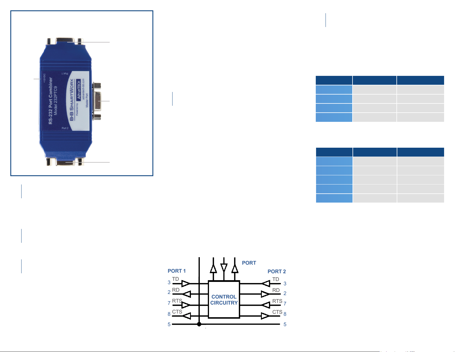
Product Overview
Master Port
DB9 female
Slave Port 1
DB9 female
Power the unit with 12 VDC.
(Recommended power supply:
Advantech Model# BB-SMi6-12-V-P230-C1)
Master Port Pinouts
Cascading Port Combiners
There are two methods of capturing the path to the master
port: RTS and Automatic Data Sensing.
The rst slave port to either raise its RTS line or transmit data,
captures the path to the master port. The path will be locked
on that slave port until it either lowers its RTS line or 60
milliseconds after the end of its transmission.
NOTE: the BB-232PTC9 does not buffer any data. Any data
sent to the opposite slave port during this period will be lost.
Power
2.5 mm
Phono
Jack
BB-232PTC9 Port Diagram
Data ow from master port to slave ports.
All data that is sent to the TX line (Pin 3 on Master port),
is broadcast to both slave ports under all conditions. This
data appears on Pin 2 of each slave port.
Data ow from slave ports to master port.
Data that is sent to the TX line (Pin 3) on the Slave ports
must compete for the path to the master port.
Slave Port Pinouts
Multiple BB-232PTC9 port combiners can be cascaded
by connecting the master port of each successive unit
to one of the slave ports of the preceding unit. Each
additional port combiner adds one slave port to the
system.
Slave Port 2
DB9 female
3
2
7
8
5
TD
RD
RTS
CTS
TD
RD
RTS
CTS
3
2
7
8
5-
RD TD RTS
2 3 7
CONTROL
CIRCUITRY
GROUND
PORT 1 PORT 2
MASTER
PORT
5
SIGNAL PIN DIRECTION
TD 3 Input
RD 2 Output
RTS 7 Output
GND 5 *****
SIGNAL PIN DIRECTION
TD 3 Input
RD 2 Output
RTS 7 Input
CTS 8 Output
GND 5 *****
Power the Unit
1
Connect Serial Cables
2
Operation - Data Flow
3
+
Pinouts
5
All ports on the BB-232PTC9 are congured as RS-232
DCE ports using DB9 female connectors. Note that a
null-modem type connection will be required to connect
the BB-232PTC9 to other DCE congured ports.
The CTS signal on each slave port indicates to the slave
devices if the path to the master port is available.
• If the slave port’s CTS line is high, data received by that
port will be transmitted out the master port.
• If CTS is low, the opposite slave port has captured the path
to the master and any data at the inactive slave port will
be lost.
For example, if both slave ports are inactive and have RTS
low, CTS will be high at both slave ports, indicating that the
path is available. As soon as one slave port captures the path
by either beginning its transmission or raising its RTS line, the
CTS signal at the opposite slave port will drop to the low state.
The RTS output on the Pin 7 of the master port follows the
RTS signal level found on the active slave port.
Handshake Signals
4


