Advantech L3P Series User manual

Model L3P
Sonic Sifter Separator
Operation & Set-up Manual
Models:
Model L3P
Model L3P-15
Model L3P-25
Model L3P-26
Advantech Manufacturing, Inc.
2450 S Commerce Dr., New Berlin, WI 53151 USA
Telephone: 262-786-1600 • (800) 511-2096 • Fax: 262-786-5074
E Mail: sales@advantechmfg.com • Web Site: www.advantechmfg.com
A Product of the United States of America


Specifications for the Advantech Model L3P
Sonic Sifter Separator
Power Requirements
Model L3P…………………………..120 volts, 60 Cycles
Model L3P-15………………………120 volts, 50 Cycles
Model L3P-25………………………240 volts, 50 Cycles
Model L3P-26………………………240 volts, 60 Cycles
Materials of Construction
Stainless Steel Test Table
Steel Cabinet and Frame
Baked Powder Finish Throughout
Acrylic Sieve Frames, Spacers, and Top Cone
Metal Column Lock
Aluminum Fines Collector Holder
Physical Dimensions
Weight……………………………………………………..… 43 lb (20 kg)
Cabinet Dimensions………………………………..…… 23”h x 10”w x 12”d
……………………………………………………………..….. 61 cm x 25 cm x 31 cm
Operating Conditions
This device will function properly at any non-condensing humidity level within the
temperature limits of 0° to 120°F (18° to 49°C). However, for test repeatability, it is
recommended that the ambient temperature and humidity be controlled. The sieves
and accessories used with this device should never be subjected to temperatures
above +125°F (52°C) or below –45°F (-43°C).
External vibrations of a low energy level will have little effect upon the accuracy of
the test results. For optimum results, the device should be operated on a stable,
level surface. This practice will help ensure an even layer of particles on each sieve.

Operating Instructions
Model L3P
Sonic Sifter Separator
Installation
Place the Model L3P Sonic Sifter Separator on a level surface for
operation. Observe the ambient temperature and humidity guidelines
outlined in the specification section.
Electrical Connection
Plug the power cord into the socket in the rear of the unit and then
into the appropriate power source as outlined in the specification
section.
Control Panel Components
On the control panel, locate the Sift/Pulse Switch; the Amplitude
Control; and the Timer. The components and their operations are
described in the following pages.
Model L3P Sonic Sifter Separator Control Panel
Sift/Pulse Switch
The Sift/Pulse Switch consists of three possible settings (Off, Sift, and
Sift/Pulse) and serves two main functions. First, it is the main power
switch to the unit itself. When rotated counterclockwise to the OFF
position, all power is shut off to the L3P circuitry. Rotating the switch
clockwise to the SIFT position enables only the sifting portion of the
unit to operate. Rotating the switch clockwise to the SIFT/PULSE
position energizes not only the sifting portion of the unit, but also the
pulse portion. The pulse is supplied by a vertical-firing
electromagnetic solenoid located beneath the table in the test
chamber. Every four seconds, a vertical pulse or shock wave is
imparted to the sieve stack to reorient the particles in the stack and
break down softly clinging or agglomerated particles. Virtually every
test procedure benefits from the use of the pulse circuitry.

Amplitude Control
The Amplitude Control adjusts the amount of “lift” applied to the
powder in the sieve stack. The density of the particles, the presence
of electrostatic or other physical bonds, and the percentage of fine
material in the sample determine the amount of lift required.
Digital Timer/Clock
The timer controls the cycle time of the sieving operation, as well as
functioning as a 24-hour clock.
Minimum operating time is 2 seconds, maximum 99 minutes 59
seconds.
1. After applying an appropriate AC to the power input terminals, the display will
be blank and the beeper will beep for ¼ second giving the user notification
that the timer is now activated. The units’ default is in Minute [Mode].
2. Setting Time of Day - Push and hold the button [SET/DISPLAY] for 1
second, the unit will default the time to 12:00am and enter the ‘Clock Set’
mode. While in this mode, buttons [MODE], [STOP] & [START/RESUME] are
disabled and the clock set LED will be turned ON. The user now can set the
time by pressing and holding either [INCREASE] or [DECREASE] button until
the desired time is achieved. If you do not wish to set the time of day, skip
step number 3.
Mode LEDs
[Start/Resume]
button
Run LED
Clock set LED
[Stop] button
[Mode] button
[Decrease] button
[Increase] button
[Set/Display]
button
Decimal point of
3
-seven segment
4 3 2 1
Decimal point of 1-
seven segment

The clock mode is a 12-hour with an am/pm display element. When the clock
is being displayed and the clock is in the pm time frame, the decimal point of
number 1-seven segment will be ON. Once the user has achieved the proper
clock value, they need to exit the clock set mode by pressing and holding the
button [SET/DISPLAY] for 1 second. After the 1 second, the beeper will beep
for 1 second giving the user notification that the mode is now exited. Once
the clock is set, the display will go blank and the clock set LED will turn OFF.
If the clock has been set and the user presses the button [SET/DISPLAY] for
less than 1 second, the display will show the current time for a 5 second
period and revert back to what was previously on the display.
3. Setting Interval Timer - In modes 1 – 3, the device functions as a simple
countdown timer. When you set the value, press the button
[START/RESUME]. When the value reaches 0, the relay is turned OFF and the
beeper beeps 6 sets of 2 (250ms) beeps.
Repeat Feature- the timer will remember the last time set. If you desire to
change the setting from the original setting, press start switch to recall
previous setting then input new setting.
To enter one of the 3 countdown modes, press and hold the button [MODE]
for 1 second. Holding down this button the mode will switch every 2 seconds.
Each time the mode switches, the appropriate LED of mode LEDs will be
turned ON and the value displayed will change to the modes default value.
An audible ¼ beep will also be heard.
Mode 1 0 – 99 second: DEFAULT DISPLAY = 01
Mode 2 0 – 99 minute: DEFAULT DISPLAY = 00.00
Mode 3 0 – 99 hour: DEFAULT DISPLAY = 00.00
Once the countdown value has been set, you can now start the timer by
pressing the button [START/RESUME]. The relay is turned ON. While the
timer is counting down the user can stop the event by pressing the button
[STOP]. The current countdown value will remain on the display. If you want
to resume the session you just need to press the start button again. Counting
will proceed from the point where stopped. During this operation, the run LED
is blinked at once a second.
Once the timer has counted down to 0 and stopped, you can execute the
same session (time value) by pressing the [START/RESUME] button again.
This will recall the timer value and display it. At this point, you have two
options. The first being the ability to change the value by using the
[INCREASE] or [DECREASE] buttons and the second being the ability to use
the same value and starting the event again by pressing the
[START/RESUME] button.
Using the SIFT/PULSE Switch
Rotate the Sift/Pulse Switch to either the SIFT or the SIFT/PULSE
position. The light at the rear of the test chamber will become
illuminated.

Removing the Stack Assembly
The stack assembly can be removed from the test chamber by
grasping the locking arms on the column lock assembly and pulling
straight down. The stack assembly will lock and the stack can be slid
straight out of the test chamber.
Disassembling the Stack Assembly
Sliding a thumb and forefinger into the openings between the lowest
sieve or spacer and the column locking arms can disassemble the
stack assembly. While steadying the stack with one hand, spread the
column locking arms with the other hand. The spring-loaded column
lock will release. It can then be carefully removed and access gained
to the rest of the stack components.
Selecting the Sieves for Analysis
Select the sieves required for analysis. The height of the testing stack
used within the L3P is a fixed height.
U.S. Standard Sieve Series – 5/8” overall height
A maximum of six U.S. standard series sieves (sieve sizes #3.5
through #635) may be used at one time. Any combination of sieves,
accessories, or spacers making up the standard stack height of six
standard sieve units may be used.
Precision Electroformed Sieve Series – 1-1/4” overall height
A maximum of three precision electroformed sieves may be used at
one time. Any combination of sieves, accessories, or spacers making
up the standard stack height equivalent to three precision
electroformed sieves may be used. When performing separations
30µm or finer, use only one precision sieve at a time.
Accessory Usage
When sifting powders 45µm and finer, or with powders of any
distribution showing high electrostatic charges, the use of the
Advantech L3-N8 Horizontal Pulse Accessory is recommended. It
takes the place of one standard series sieve (5/8” height). The
operating principle is the introduction of a high-speed shock wave sent
across the sieving medium. The net result is a further reorientation of
particles, a shearing action on agglomerated particles, and a reduction
of screen blinding (plugged openings).
For more information on specific applications, contact your Advantech
Manufacturing representative.

Preparation for the Analysis
To prepare for the analysis of a powder sample for the first time, it will
be necessary to perform a few simple tasks:
Gather the Ancillary Equipment Needed:
•Weighing device (balance or scale with resolution in grams
suitable for your application; generally, 0.1g or 1.01g are
sufficient) 100g capacity is suitable.
•Camel hair paint brush for brushing fine particles from the
standard sieves wire cloth or precision mesh frames. (NOTE:
Brush sieves from the underside ONLY! Never force material
through a sieve opening. Never brush precision mesh.)
•Means of recording and calculating tare weights, sample
weights, percentages, etc.
Note: In addition, prior to performing the first test, all sieve,
standard spacers, and the top cone should be washed according
to the care section that follows. This step will reduce the
chance of sample contamination from any residues left over
from the manufacturing process.
Performing the Analysis
The following steps constitute a typical analysis with the L3P Sonic
Sifter Separator:
Weighing the Parts
Weigh and record the tare weights of the diaphragm, top cone,
spacers, sieves, and fines collector.
Installing the Fines Collector
Install the fines collector in the fines collector holder. Fasten the
round metal plate at the bottom of the fines collector to the fines
collector holder by sliding the keyhole slot in the fines collector over
the fastener mounted in the fines collector holder base.
Assembling the Sieve Stack
Assemble the sieve stack with the coarsest sieve on the top of the
stack and finest sieve at the bottom. If fewer than six (6) standard
series or three (3) precision electroformed sieves are used, add
spacers as necessary to fill out the proper stack height as described in

the Selecting the Sieves for Analysis section above. If spacers are
necessary for operation, they should be placed at the top of the stack.
Introducing the Powder
Discussion of the proper methods of extracting gross samples and
preparing test samples for analysis is far too complex to be dealt with
here. For more information on sample extraction and preparation,
contact your Advantech Manufacturing representative for the
publication, Test Sieving: Principles and Procedures.
A good rule of thumb is to use the smallest sample size possible that is
still representative of the lot from which it was extracted. Sample
sizes of 1 gram are a good starting point for Sonic Sifter Separator
determinations. The sample size can be increased until the optimal
combination of sample size, time, and sift amplitude are determined.
Our Customer Service Laboratory can be consulted at no charge for
suggestions on test parameters for powder samples.
Select a proper mass of powder to be tested. When sieving materials
larger than 38 µm; do not exceed 20g. When sieving materials
smaller than 38µm, do not exceed 10g. Weigh and record the mass of
the powder sample. Place the powder sample on the top sieve in the
stack.
Installing the Diaphragm
The diaphragm is placed on top of the top cone with the metal ring
protruding downward. The proper orientation of the diaphragm can be
determined by the word “TOP” stamped on the latex material.
Replacing the Column Lock
Place the column lock onto the sieve stack and press straight down
until the locking arms snap onto the fines collector holder.
Check the Control Panel
As a safeguard, make sure the amplitude control is set at “0” and the
timer is in the “CLOCK” mode or the display is blank before placing the
stack assembly into the test chamber. This is necessary to prevent
damage to the sieves and the integrity of the test sample in the
chamber. If the amplitude had been inadvertently set to the
maximum setting or the timer interrupted mid-cycle, for example, the
sudden impact of the signal from the loudspeaker could damage the
sieves or compromise your test sample.

Inserting the Stack Assembly
Slide the stack assembly into the test chamber with the column arms
locked. The stack assembly is stopped at the top by two tabs on the
driver support plate. On the test chamber table, you will notice two
rivets that will limit how far the stack can be placed inside the
chamber. Also on the floor of the test chamber is the table switch, a
safety interlock device that prevents the unit from operating if the
stack moves forward out of position. This switch will be properly
deployed and the circuit activated if the stack is inserted correctly.
Once the stack assembly is in position, the column lock can be
released by sliding a thumb and forefinger into the openings between
the lowest sieve or spacer and the column locking arms. Spread the
column locking arms. The spring-loaded column lock will release and
expand to lock the column into the test chamber, forming an airtight
seal. Close the sliding door to the test chamber.
Beginning the Test
Rotate the SIFT/PULSE switch to the PULSE setting. While virtually all
test procedures benefit from the use of the PULSE circuitry, some may
not. Use the setting appropriate to your samples.
Setting the Amplitude
Note: The amplitude is the “lift” particles see as the oscillating air
column is set in motion. The higher the amplitude setting, the more
lift on particles. Moving the particles more vigorously than necessary
DOES NOT increase the speed or precision of the separation. In fact,
excessive amplitude settings may increase electrostatic problems,
sample loss, and equipment wear.
WARNING: Due to the extremely fragile nature of the Precision
Electroformed Series sieves, excessive amplitude, especially over
extended periods of time can cause immediate or premature sieve
failure.
After starting the timer, increase the amplitude SLOWLY until the
largest of the particles begins rolling on the top sieve. The entire
operation can be viewed through the sidewalls of the sieves. The finer
material should begin flowing through the sieves within seconds. Each
particle is being lifted off of the screening surface and set back down
on the sieve openings 60 times per second when using 60 Hz current
(50 times per second when using 50 Hz current).

Completing the Test
For an initial test run: When no more material can be seen falling
through the sieves, note time elapsed. This value should be used for
subsequent testing of the same material to assure repeatable results.
For a routine test run: When the timer counts down to “0”, open
the door and follow the procedures listed for ‘Removing the Stack
Assembly’. Caution should be exercised when dismantling the stack
assembly to avoid any loss of sample retained on the sieves or fines
collector.
The parts can be weighed directly on the weighing device, removing
the need to transfer the powder to a weighing dish (thus reducing
potential sample loss). Don’t forget to weigh the fines collector as
well. Record the weights on the worksheet used to record the tare
weights. Subtracting the tare weight from the post-test weight yields
the mass of the sample retained on the part. The percentage retained
at each sieve size can be calculated simply by comparing the weight
on each part with the starting sample weight.
CARE OF ADVANTECH MODEL L3P SONIC SIFTER SEPARATOR
AND ACCESSORIES
The Advantech Model L3P Sonic Sifter Separator and Accessories will perform
satisfactorily for many years if the following basic care instructions are observed:
Cleaning the Sieves and Stack Assembly Parts
For best results, stack assembly components and sieves should be
cleaned in an ultrasonic cleaner of 150 watts or less. General cleaning
is best accomplished in a mild solution of dishwashing detergent and
water maintained at 75-80°F (24-27° Celsius). Ultrasonic cleaning has
proven to be the most effective method of removing particles plugging
woven wire cloth sieve openings. Regular ultrasonic cleaning will help
prevent particle buildup in the sieve openings, thus reducing the
amount of time each sieve must be exposed to ultrasonic vibrations.
Care must be taken in how long the sieves are exposed to the
ultrasonic vibrations, as damage can result from overexposure. Do
NOT ultrasonically clean precision sieves.
After washing, rinse the parts with tap water, and allow to air dry. DO
NOT expose the sieves, spacers, or top cone to heat sources of any
kind. Heat sources will cause warping and/or cracking of the parts
which will compromise the airtight seal between the stack assembly
parts during use. If an ultrasonic cleaner is not available, immerse
items to be cleaned in the same mild detergent solution, rinse and
allow to air dry as directed. Precision (electroformed) test sieves
have very specific warnings and care procedures. Please refer
to the Handling and Use Instructions on the jewel case.

CAUTIONS
U.S. Standard Sieve Series: Improper handling can cause
serious damage to the sieve openings and accelerate sieve failure.
•DO NOT remove particles clogging sieve openings
with a needle or other sharp object.
•DO NOT use compressed air to clean the sieves or
dislodge trapped particles.
Precision Electroformed Sieve Series:Store the precision
electroformed sieves in the protective plastic storage box provided.
Refer to the Handling and Use Instructions on the sieve jewel case.
•DO NOT remove particles clogging sieve openings
with a needle or other sharp object.
•DO NOT brush the electroformed media.
•DO NOT touch the electroformed media with your
fingers. The natural acids and oils in the skin will
attack and discolor the fragile electroformed mesh and
cause permanent failure.
•DO NOT ultrasonically clean precision electroformed
sieves.
Cleaning the Fines Collector and Diaphragm
The fines collector and diaphragm are made of durable latex material.
With regular care, these parts can withstand a considerable number of
duty cycles. Both parts can be cleaned in a mild detergent and water
solution and rinsed with water. The parts should be allowed to air dry,
avoiding heat and sunlight.
After drying, both parts should be dusted lightly with talcum powder
(NYTAL 200 or any commercial unscented talcum powder). The excess
talcum powder can be blown off with low-pressure compressed air.
Return the parts to their protective foil envelopes for storage, as light
and some chemicals in the air can be harmful to the latex, causing
holes and cracks to appear prematurely.
Users’ Tip: For longer life of the fines collectors, rotate the use of
several collectors over time. For example, use fines collector #1 on
Monday, wash and store the collector at the end of the day and use
collector #2 on Tuesday, etc. Set up a regimen to rotate 3-5
collectors over the course of a week, or whatever your usage requires.
Allowing the latex to ‘rest’ before it is put back into regular service can
significantly extend the life of the individual collector.

Cleaning and Care of the L3P Sonic Sifter Separator Unit
The Sonic Sifter Separator cabinet, test chamber and aluminum stack
assembly parts should be wiped off periodically with a soft, damp
cloth.
Servicing the L3P Sonic Sifter Separator Unit
Only personnel qualified by Advantech Mfg. should service the Sonic
Sifter Separator. If any performance or operational problems arise,
please contact Advantech Mfg. directly.
ADVANTECH MODEL L3P SONIC SIFTER SEPARATOR LIMITED
WARRANTY
Advantech Mfg. guarantees all its apparatus against defective material and
workmanship for a period of one year from the date of delivery. This
guarantee is limited to repair or replacement of the defective apparatus in our
factory in New Berlin, Wisconsin. Advantech Mfg. does not assume
responsibility or accept invoices for unauthorized repairs to its apparatus.
Under no circumstances shall Advantech Mfg. be liable for loss of profits or
other damages.
Advantech Mfg. is not responsible for damage to apparatus due to improper
installation or operation beyond its rated capacity (intentional or otherwise).
It is distinctly understood that the above covers all conditions under which
Advantech Mfg. apparatus are sold.
For warranty claims or other service requests, please obtain return
authorization prior to shipment by contacting:
Advantech Manufacturing
Customer Service Department
2450 S. Commerce Drive
New Berlin, WI 53151
Phone: 800-511-2096 or 262-786-1600
Fax: 262-786-5074
www.advantechmfg.com


Test Sieving: Principles and
Procedures
A Discussion of the Uses, Capabilities, and
Limitations of Testing Sieves as Analytical Tools
ADVANTECH MFG., INC.
THE LEADER IN SIEVING TECHNOLOGY®
2450 S Commerce Drive
New Berlin, Wisconsin 53151
262-786-1600 (800) 511-2096
FAX 262-786-5074
sales@advantechmfg.com
www.advantechmfg.com

Foreword
Through ASTM and many industry organizations, standards have been
established for particle size for powder, granular and larger sized
materials. This manual has been prepared to help guide users of test
sieves through the proper procedures as well as provide many
additional tips that can enhance the existing procedures.
Our aim is to provide assistance to both the experienced and non-
experienced particle technologist in developing comprehensive particle
size test results, reduce test variations and enable the user to isolate
and identify sources of error or variations in the data.
Advantech Test Sieves, manufactured in the U.S.A., are the most
accurate test sieves available in the world today. The use of Advantech
Test Sieves will provide more precise and reproducible data, resulting
in better product control and a possible reduction of variables.
In preparing this manual, we have drawn from sources in the ASTM
publications, ISO Standards and various papers written by some of the
most renowned figures in the particle technology world. Additionally,
Advantech personnel have contributed sieving technology
developments after having logged numerous years of "hands-on"
experience with many experts in the field. The result is a melding of
standards, research and opinion to provide a solid foundation for your
own particle size analysis program.
If additional help is desired in establishing your sieve analysis
procedure, or if you desire a list of suppliers of the equipment
highlighted in this manual, please contact Advantech
Manufacturing, Inc. 2450 S Commerce Dr., New Berlin, WI
53151
Telephone (800) 511-2096 or email: sales@advantechmfg.com
Copyright© 2001, Advantech Mfg.

Table of Contents
CHAPTER 1 -
. . . . . . . . . . . . . . . . . . WHAT IS SIEVING?
CHAPTER 2 -
. . . USES, LIMITATIONS AND ADVANTAGES
CHAPTER 3 -
. . WORKING GLOSSARY OF SIEVING TERMS
CHAPTER 4 -
. . . . . . . . . . . . . . SIEVE SPECIFICATIONS
CHAPTER 5 -
. . . . . . . SIEVE CALIBRATION PROCEDURES
CHAPTER 6 -
. . . . . . PERFORMING THE SIEVE ANALYSIS
CHAPTER 7 -
. . . . . . . . . . . SIEVE CARE AND CLEANING

CHAPTER 1
WHAT IS SIEVING?
A simplistic definition of sieving is the
separation of fine material from coarse
material by means of a meshed or
perforated vessel. Professor Terence Allen
characterizes sieving as "The aperture of a
sieve may be regarded as a series of
gauges which reject or pass particles as
they are presented to the aperture." (1) This
theory was actually in practice during the
early Egyptian era as grains were sized
with 'sieves' of woven reeds and grasses.
The level of sophistication increased
with the rise of the industrial revolution
and the need for more sophisticated
methods for classifying material by their
particle size. As requirements for sized
material rose, technology in producing
uniform sieving media increased. Woven
wire cloth was introduced as an alternative,
providing greater accuracy and durability.
At present, this woven cloth is available in
a range of sizes from 125 mm (5")
openings to 20 micrometer openings.
All mesh sizes are covered by both national
and international standards.
The need for particle size analysis in the
finer size ranges (i.e. 38 micrometers and
less) prompted the development of the
electrodeposited sieve. These sieves,
sometimes called electroformed or
micromesh, are currently being produced
with openings as fine as 3 micrometers.
The mesh openings are extremely uniform
in both size and shape and maintain
exacting tolerances.
While the technology related to sieve
analysis has come a long way since the
reed sieves of ancient Egypt, few new
developments have come along since the
1940's. Professor Kurt Leschonski wrote
"Sieve analysis is one of the few methods
of particle size analysis which has escaped
modernization." (2)While the modernization
has not come in the actual hardware of
sieving, refinements in the application and
utilization of existing equipment has
proceeded.

CHAPTER 2
USES, LIMITATIONS AND ADVANTAGES
Harold Heywood wrote "I often refer to
sieving as the 'Cinderella' of particle size
analysis methods; it does most of the hard
work and gets little consideration."(3)
There are numerous reasons for the
selection of high quality testing sieves as a
first choice in particle size analysis work.
Leschonski said "... because of its
simplicity - everyone immediately
understands the purpose of a stack of
sieves and its operation -and its
inexpensive- ness." (4) Standard sieve
analysis is probably the fastest and most
widely used quality control procedure in
any powder process control industry. Used
frequently as a mediating device between
the production and sales divisions of a
process corporation or between the sales
force and the customer, test sieve analysis
work enjoys the universal recognition of
being the best 'quick and dirty' test
procedure for rapid particle size distribution
data. The outcome of the analysis is easily
calculated and interpreted for comparison
between laboratories. Start-up cost to
institute a basic sieving quality control
program is minimal, and operators at most
levels of training are capable of performing
a successful sieve analysis. With these
factors in mind, it is easy to see why
testing sieves are as ubiquitous as they are
in industry. Materials from crushed ore
chunks of over 114.3 mm (4 ½”) in
diameter to slurred alumina and porcelain
powders of less than 20 micrometers are
all analyzed with test sieves on a regular
basis.
Whether hand or machine sieving, wet or
dry preparations, analysis or production
work, testing sieves have found a niche in
the quality control laboratory. Given this
overall acceptance of test sieves as a viable
analytical device and the widespread
presence of the sieve in laboratories of all
industries, any shortcomings of such an
analytical device would be magnified. For
all of the advantages available to the test
sieve user, limitations must be recognized
and accounted for in the presentation and
analysis data.
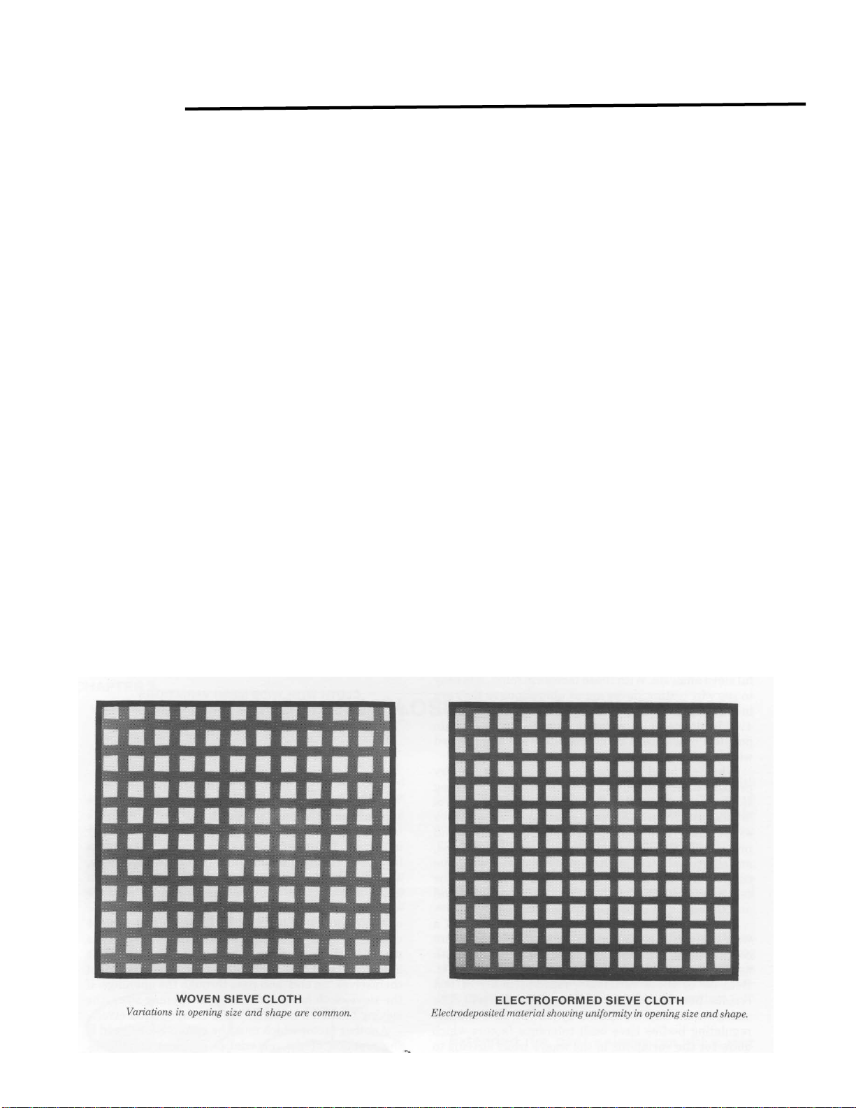
Test sieves are individuals. Being
fabricated of a woven mesh material,
variations in the weave are common. The
chances of locating two sieves with an
identical distribution of opening sizes are
extremely remote. Due to these variations,
the reproducibility of test results between
sieves can be adversely affected. The
stringent standards imposed by ASTM, ISO
or other regulating bodies have established
tolerance factors which allow for the
permissible variations in the weave while
striving to maintain a level of uniformity in
the performance of the 'test grade' sieve
cloth. (See Table 1)
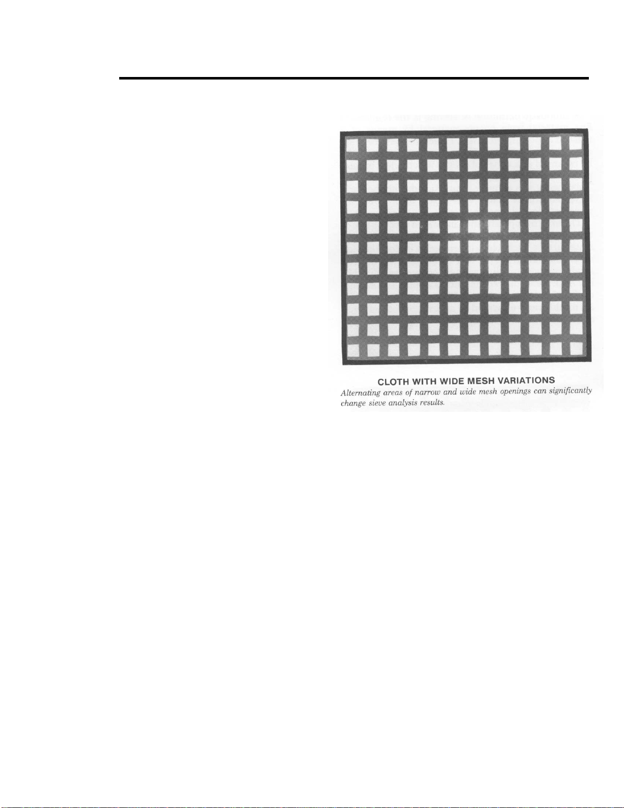
With this variation of opening sizes
present, some smaller than the nominal
and some larger, the time interval of the
sieve analysis becomes extremely
important. If, for example, a sieve has
several openings far above the nominal
opening size for the particular mesh size,

and the test is run for 30 minutes, the
probability of larger-than-nominal particles
finding those oversized openings is much
greater than if the test was run for only 15
minutes. Similarly, if the sample of powder
contains a large percentage of elongated or
needle like particles, a longer test interval
would provide a greater likelihood that the
elongated particles will orient themselves
‘on end’ and pass through the openings. If
the sieving cloth has a wide range of
opening sizes, the sieving of this type of
material has a compounded error.
Another factor which must be
considered is the reaction of the material to
ambient conditions. The most accurate
test sieve available would be of minimal
use if the relative humidity in the test lab
was 99%. Extremely dry conditions can
cause fine powders to adhere to the sieve
components and each other with strong
electrostatic charges. Additional types of
sieving problems are discussed in the
glossary section.
To minimize error caused by wire cloth
variation, steps must be taken at every
stage of fabrication that will assure the
uniformity of the woven mesh as well as
the compliance with the applicable
standards. Both the weaver and the test
sieve manufacturer must maintain a
constant monitoring program measuring
the actual opening sizes of the wire cloth
as well as the uniformity of those openings.
The loss to the manufacturers in rejected
out of specification sieve cloth is a gain to
the end-user in uniformity and compliance.
This manual suits for next models
4
Table of contents
Popular Water Filtration System manuals by other brands

ACO
ACO Lipumax-C-FST installation instructions

Kessel
Kessel SE M NS 2 Installation, operation and maintenance instructions

Chandler Systems
Chandler Systems DROP installation manual

STA-RITE
STA-RITE PRC50 owner's manual

US Water Systems
US Water Systems Fusion Service manual

Pulsar Ultraviolet
Pulsar Ultraviolet 405-PUV-100-02 Operation & installation instructions