Innowater SMC10 User manual
smc chlorinator
manual
03-21

Page
1 Introduction 1
2 Technical characteristics 2
3 Chlorinator 3
4 Installation 4
5 Water preparation 6
6 Adding salt 7
7 Operation 8
8 Menus 9
9 Fault messages 12
10 Recommendations and Warnings 13
11 Manual Cell Cleaning 14
12 Warranty, Technical Service and
Spare Parts 15
All Rights Reserved

1 SMC
1. INTRODUCTION
We thank you for your purchase of an Innowater chlorinator. Innowater chlorinators
are manufactured following the strictest quality controls using the most advanced
technology of electrolysis resulting from our many years of swimming pool industry
experience .
With minimum maintenance and following elementary rules for installation and use,
you will enjoy an extremely efficient device for many years.
Please read this manual carefully before installation or start-up, and keep it for
further reference.
The sections concerning the installation require certain technical knowledge and we
always recommend that installation is conducted by an industry professional.
Please pay special attention to the points marked with the following symbol:
Any damage caused to the chlorinator resulting from not complying with these
warnings may lead to a void of warranty.
We trust you will enjoy your Innowater chlorinator—thanks for choosing Innowater.

SMC 2
2. TECHNICAL CHARACTERISTICS
SMC10 SMC15 SMC20 SMC30
Maximum flow lt/min 450 450 450 450
Maximum pressure bar 4444
Pressure drop kpa 5555
Chlorine production gr/h 10 15 20 30
Max. output voltage VDC 24 24 24 24
Max. Output current ADC 2,0 2,5 3,5 5,0
Cell configuration Bipolar Bipolar Bipolar Bipolar
Recommended salt
concentration gr/l 5-35 5-35 5-35 5-35
Cell housing material PC PC PC PC
Cell life span h 14.000 14.000 14.000 14.000
Electrode substrate material Titanium
grade 1
Titanium
grade 1
Titanium
grade 1
Titanium
grade 1
Maximum swimming pool size m3
- Temperate climate 30 50 90 150
- Tropical climate 20 34 60 100
Power supply VAC 230 230 230 230
Power consumption W 58 75 100 144
Weight Kg 3,2 3,5 4,0 4,3

3 SMC
3. CHLORINATOR DESCRIPTION
You will find the following items in your Innowater SMC box:
1 Control unit
a LCD screen
b Keyboard
c DC cell cable and connector
2 Power supply cable
3 Electrolytic cell
4 Cell housing
5 Thread lock
6 Cell O Ring
7 Cell tap
3
42
5
b
a
c
1
6
SMC 4
Chlorinator Control Unit
Mount the control unit on a wall using the bracket on the back and the screws
provided. Choose a place for easy access and reading. The control unit can only be
placed at a maximum of 1.5 meters away from the electrolytic cell due to cable
length. Choose a place with good ventilation and protection from the rain and other
possible water leaks or splashing.
We recommend that you have an electrical safety circuit breaker
fitted to your swimming pool electrical circuit.
Connect the earth wire (yellow and green) of the 230 VAC power supply cable to
the earth of the swimming pool electric panel. Connect the phase (brown) and the
neutral (blue) to the output contacts of the pump contactor in such a way that the
chlorinator will be powered only when the pump is working. Connect the chlorinator
wires to non occupied contacts. Do not use the contacts in use by the pump.
This will prevent the chlorinator to be electrically connected to the pump when the
contactor is switched off what could cause serious damage. Verify that the
chlorinator switches off itself when the pump stops. This operation should be
performed by a professional.
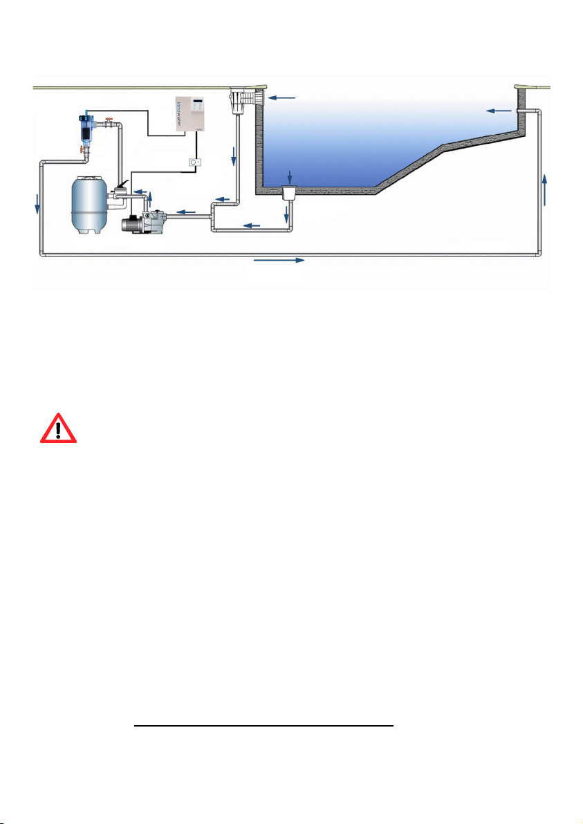
Cell housing
The cell housing must be installed in the return flow to the swimming pool and as
the last element the water goes through before returning to the pool: always after
the filter and any the heat pumps, solar panels, etc. Use special glue for rigid PVC
and wait until it completely dries before inserting the cell.
4 INSTALLATION
5 SMC
If an automatic pH regulation system has been installed, the
injection of the acid must take place unconditionally after the cell.
Otherwise, the electrodes will corrode due to the acid contact and
the warranty will be void. Do not place the acid tank near the
chlorinator with insufficient ventilation as the gases will corrode the
electronic components quickly. Any acid containers should be kept
outside of the plant room.
Whenever it is possible, a by-pass installation with three valves is recommended. This
allows the amount of water flowing through the cell to be adjusted and the swimming
pool to work with the cell housing disassembled. In any case, when there is a high
flowing single speed pump, the by-pass is necessary to reduce the speed of water
through the cell housing to lower the pressure and avoid vibrations.
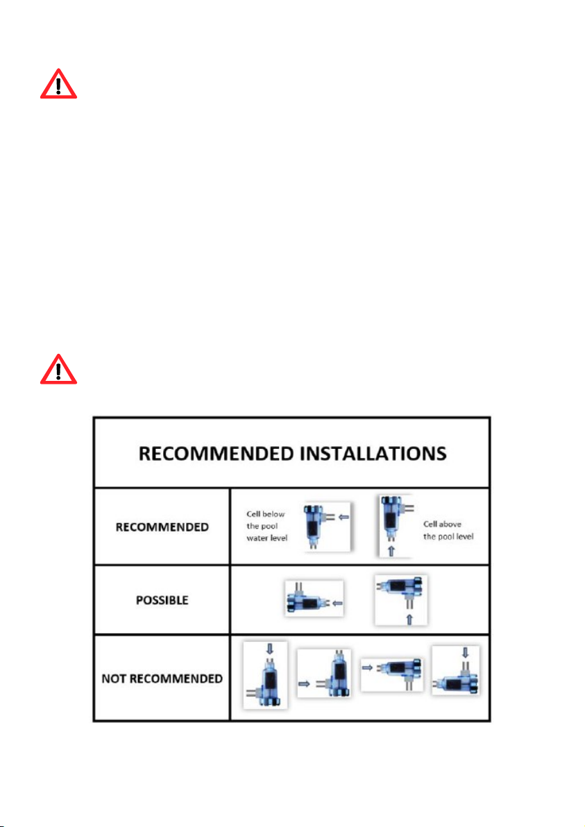
Although the vertical cell position is recommended, the cell housing may be installed
vertically or horizontally, according to the characteristics of your site. The vertical
position also allows for disassembling the cell without water spillage. Allow enough room
to unscrew the thread and extract the cell once the housing has been installed. WATER
MUST ENTER THE CELL THROUGH THE HIGHER SIDE OPENING.
A good filtration is essential in salt chlorination. Please, verify that your
filter and filtrating material are in optimal working conditions.

SMC 6
5. WATER PREPARATION
Use preferably water from the metropolitan network. If water from a different origin is
used, have it analyzed and verify so that there is no contraindication regarding salt
electrolysis (such as a high concentration of metals or calcium, for example). Make
also sure the water complies with health standards.
Balance the water before starting your chlorinator and add the amount of chlorine
stabilizer prescribed by the manufacturer (usually 1 kg per 25m3 of water). Do not
exceed the dose because this will block the disinfection action of the chlorine.
NOTE : Stabilizer prevents the disintegration of chlorine due to UV radiation. The lack
of stabilizer could make it difficult to reach a chlorine residual concentration during
high sunshine periods and will oblige you to produce more chlorine reducing the life
span of your cell. In general, and specially if you don't use stabilizer, we recommend
to chlorine during low sunshine hours.
The water must be clean and clear, presenting the following parameters:
Salt 5-6 kg/m3 (gr/l)
pH 7,2-7,6 (cement) 6,8-7,0 (polyester)
TAC 60-100 ppm
TH 15-20º French
Stabilizer 20-30 ppm (or according to the indications by the
manufacturer)
Temperature >10 º C
Cell
Insert the cell in the cell housing making sure that its open side window is pointing
to the side water inlet. Make sure the O-ring is fitted correctly and tighten the thread.
Then, connect the cell cable connector to the cell terminals. Verify that the connector is
orientated so that its small hole is aligned with the thin pin on the cell before trying to
plug the connector.
NOTA: The cell pins should only be tighten slightly and always by hand. Never use a
tool because the cell could be damaged. Water tightness is assured by the internal seal.
7 SMC
6. ADDING SALT
The chlorinator must remain OFF during this operation and until the
additive is completely dissolved. Operating the chlorinator with non
dissolved salt could irreversibly damage the cell and the power supply,
and lead to a void of the warranty.
Calculate the volume of the swimming pool and add 5 to 6 Kg of salt per cubic meter.
Make sure the chlorinator is disconnected and make the filtration system to work for at
least 24 hours.
For any new pool builds please wait for four weeks before adding salt
into any recently cement coated pool or discuss this with your pool
builder.
The salt dissolving process can be accelerated using the pool cleaner. Check the salt
concentration is between 5 and 6 kg/m3 using a kit from a specialized pool shop.
The salt chlorination process doesn’t consume salt. However, the salt concentration may
be reduced over time due to the rain or other periodic freshwater contributions (filling
up, filter cleaning, etc.). Whenever the salt concentration needs to be corrected, pour
salt as close as possible to the return lines. Never pour salt in the skimmers or in the
drain inlet.
SMC 8
7. OPERATION
The chlorinator and its different menus are controlled with a four key keypad. Three of
these keys, Λ , MENU and OK, also have a secondary function accessible by pressing
and holding down the corresponding key for 2 seconds
NOTE: At some points of activity or during a change of function the keyboard may
seem as it is not responding immediately. This is completely normal. Just wait a few
seconds for the task to be completed and the display will respond.
7.1 ON/OFF
The ON/OFF function (MENU key held for 2 seconds) turns the chlorinator
alternatively ON and OFF.
Once the chlorinator is switched on, the main production screen will appear:
This screen indicates the current production rate and the existing salt level in the
water. It may take a few seconds for the salt level to appear. If you are on a different
screen you can always come back to the production screen by pressing the MENU
button repeatedly.
To increase or decrease the chlorine production rate press the Λ or V arrows. The
chlorinator modules the production by varying the operating time in periods of 10
minutes. At 100% the chlorinator works constantly.
You will soon get to know the needs of your pool which will depend on the different
conditions (number of users, temperature, etc.) allowing you to anticipate in the
production setting. In general, to enjoy the benefits of salt water chlorination, we
recommend setting the minimum production rate that produces a crystal clear water
in your pool. Avoid chlorinating during high sunshine hours because chlorine will
quickly disappear due to the UV radiation and won’t have the time to disinfect your
pool thoroughly. We recommend to program the chlorinator during the night or at low
sunshine hours.
Production: 70%
Salt: OK
OFF

9 SMC
7.2 SHOCK FUNCTION
The shock function allows you to apply a shock treatment (chlorinator at 100%) for a
selectable period of time with automatic return to the previous production rate once the
shock period has ended. This feature is useful if the chlorine level has fallen suddenly
for some reason and you want to recover it quickly.
To activate the shock, go to the production screen and press Λ SHOCK for a few
seconds. The following screen will appear:
Select a number of hours, by using the Λ or V arrows
and press OK to accept or MENU to exit. If you click
OK, you will enter the Shock function and the
following screen will be displayed:
If you want to quit the Shock function press any key.
The following screen will be displayed:
Press OK to exit the shock function or MENU to
continue the shock treatment.
8 MENUS
8.1 Language menu
From the main screen press MENU. Press V until the following screen will appear:
Press OK to enter the Language menu.
Choose a language using the arrows Λ V and confirm
by pressing OK. Press MENU to return back to the
production screen. You can also exit without saving the
setting by pressing MENU.
8.2 Polarity Menu
The polarity applied to the cell is periodically reversed to remove calcium build-up. The
factory pre-programmed period is 8 hours and this is recommended. Depending on the
conditions of your pool it may be necessary to reduce this period in order to increase
the frequency of cleaning. Note that the longer this period is, the longer the cell
duration will be. A period of less than 4 hours will drastically reduce the life of the cell.
Inversely, you can increase this period if your cell doesn’t need to be cleaned that
Shock 7 h
Select duration
SHOCK 7 h
Remaining: 07:00
Exit Shock?
YES:OK NO:MENU
MAIN MENU
1 Language

SMC 10
frequently. We recommend, in general, to set this period to the larger number of hours
as long as there is not calcium build-up on the electrodes.
To change the polarity period, go to the production screen and press MENU. Press the
Λ or V keys once or more until the screen on the left will appear.
Then press OK.
Use the Λ or V buttons to select the period and then press OK to confirm and save the
setting. Then press MENU once or more to return to the production screen. You can
also exit without saving the setting by pressing MENU.
NOTE: When a polarity change is taking place, the unit
will enter a pause mode lasting 10 minutes. This will be
indicated by the screen on the left.
8.3 T V I Readings
TVI readings are used to assist us in diagnosing if any issues arise.
This menu allows you to read find the temperature inside
the control unit, the voltage applied to the cell and the
current passing through it. These parameters can be
very useful when servicing or diagnosing.
8.4 LCD contrast
Adjust the LCD contrast using the Λ or V keys.
Press OK to save and exit.
Chang. polarity
remaining: 8 min
MAIN MENU
2 Polarity per.
Polarity 7h
Select period
T= 29.8ºC
V= 23.40V I=3.4A
MAIN MENU
3 T V I readings
LCD contrast
- ■ ■ ■ ■ ■ ■ +
MAIN MENU
4 LCD Contrast
11 SMC
8.5 External control
TVI readings are used to assist us in diagnosing if any issues arise.
This function allows you to use the external control input to change automatically the
percentage of production. External control input works by connecting the two wires of
the control cable (optional) to a dry contact. If you have a cover, for example, you can
use it to reduce or stop production when the cover is extended. You can also use it to
control the chlorinator with a chlorine or redox regulator.
When the external control signal is detected the display
on the left and the production is locked to the control
percentage programmed.
NEVER connect the external control cable to a contact with voltage.
Connect it only to a dry contacts (voltage-free).
8.5.1 Contact type
Select the behaviour of the relay to be connected to the external control input:
Open = active Ext. Control will activate when the contact open
Closed = active Ext. Control will activate when the contact close
8.5.2 Production
Choose the production percentage when the external control signal is detected.
If you are using an Innowater chlorine or redox regulator, program the relay
output of the regulator in ON / OFF mode and the chlorinator input as Open = active
and Production if active 0%
CONTROL EXT: 70%
SALT: OK
MAIN MENU
5 Ext. control
OK EXT CONTROL MENU
1 on/off
EXT CONTROL MENU
2 Contact type
OK Contact type
open = active
EXT CONTROL MENU
3 Production
OK Production if
active 50%
SMC 12
8.6 pH config
This menu is used with the pH Wireless option. See the
Wireless Pump manual for configure the function.
8.7 Factory configuration
This menu is used for factory settings and its parameters
must not be modified by the user.
9 Fault messages
This screen is displayed when the water does not contact the probe in the cell and the
control system stops the production. Firstly verify that there is water in the cell and that
its level reaches the top where the probe is located.
A low water level in the cell may be due to a dirty filter, obstructed skimmer basket,
obstructed pump basket or to a pump not powerful enough. As soon as the water level
is restored the fault disappears.
This screen appears when the salt concentration in the water is too low. At this stage it
would be best to take a water sample up to your local pool professional for testing and
then add the required amount to maintain a level between 3000-4000 ppm. As previ-
ously advised, wait until the additive is completely dissolved before running the chlorin-
ator. Then press any key to restart the chlorinator.
PLEASE NOTE: This screen can also be displayed if the water temperature is too low, if
there is a bad electrical connection between the control unit and the cell or if there is
calcium built up on the electrodes. If the water test shows your salt levels to be correct
please assess the cleanliness of your cell, the cell connection or it may be a fact of cold
water temperature only.
MAIN MENU
6 pH config
MAIN MENU
7 Factory conf.
LOW WATER
LEVEL IN CELL
SALT TOO
LOW
13 SMC
10. RECOMMENDATIONS AND WARNINGS
The bipolar cells of your Innowater chlorinator have been manufactured using an
exclusive technique and rigorous quality controls conferring extraordinary duration and
resistance. However, there are several factors that may irreversibly reduce the
properties of any electrode that you should avoid in order to obtain the best
performance and longest lifespan of your chlorinator. These are:
- Operating with calcium build up on the electrodes
- Excessive chlorine concentration (chlorine is corrosive above 3.0 ppm)
- pH too low or too high
- Insufficient salt concentration
- Adding salt to the pool with the chlorinator working
- pH corrector acid injection before the cell housing, in the
skimmers or in the bottom drain inlet
We recommend you to periodically check the cell for calcium build up, corrosion or
leakage. The rods insulation and top sealing must be in perfect condition. If there is any
damage please send the cell to the technical service for replacement.
NEVER operate the chlorinator if:
- Your installation is not provided with a residual current circuit breaker
- Water is not flowing through the cell
- Valves are closed
- The filter is being cleaned
- The swimming pool is being emptied
- The water is frozen
- Electrodes are blocked by calcium build-up
SMC 14
11. MANUAL CELL CLEANING
Your Innowater chlorinator is provided with a self-cleaning polarity change system
that in normal conditions eliminates maintenance work. However, in exceptional
cases, when the calcium concentration is very high (very hard water, old concrete
pools), polarity change may not be enough to completely eliminate the calcium build
up. Visually inspect the cell regularly to detect the presence of calcium and, if
necessary, clean the cell manually. Let the cell dry completely during one or more
days for the calcium build up to detach by itself. You can help this by slightly knocking
the cell but do not introduce any element that could scratch the electrodes. Their
coating is fragile. You can also use a high pressure water jet. DO NOT USE ANY
METALLIC OR STABBING ELEMENT TO SCRATCH THE ELECTRODES.
If you are not able to remove the calcium build up in the way described, proceed as
follows:
1 Turn off the pump and the chlorinator.
2 Disconnect the power cable for the cell, unscrew the thread lock and extract the
cell.
3 Immerse the electrodes in a hydrochloric acid solution made from 1 part of acid
and 9 parts of water. Do not immerse the rods or the cap of the cell. The hydrochloric
acid will react with the calcium and will dissolve it producing a fizzing sensation.
4 Once the calcium build up has dissolved, rinse the cell immediately with
freshwater, dry the terminal area properly and reinstall the cell in its housing.
Never leave the cell in the acid solution for more than 5 minutes.
Do not scratch the electrodes with metal objects. For safety
reasons, always add the acid into the water and never inversely.

15 SMC
12. WARANTY, TECHNICAL SERVICE AND SPARE PARTS
Warranty
1. The electrolytic cell and the control unit will be guaranteed for 3 years against any
manufacturing defect.
2.The manufacturer declines any responsibility in the following cases:
a. If the instructions in this manual are not followed
b. Faulty electrical connections
c. Accidental damage
d. Damage due to water in the control board
e. Pump of more than 1.5 V power without installation of a “By-
Pass” (according to assembly diagram on page 4)
f. If acids are poured into the skimmers or cell without having disconnected
the rectifier.
g. Presence of an acid tank near the chlorinator with insufficient ventilation.
h. Operation with calcium built up on the electrodes.
3. The chlorinator shipping cost will be paid by the client/distributor.
4. It should be clarified that the Innowater chlorinator installation is completely
independent from the filtration equipment, pump or multi-port valve. All they have in
common is their connection.
Spare parts
Innowater have spare parts available at your disposal via a network of pool shops
around the world. The use of non-original parts or the manipulation of the equipment by
personnel not authorised by Innowater may cause serious problems to your chlorinator
and will void the warranty.
If you do require any servicing or spare parts please contact us directly at
www.innowater.es.

This manual suits for next models
3
Table of contents
Other Innowater Water Filtration System manuals


