ADWEL DRM-100 User manual

User Manual
Model DRM-100
Digital Resistance Meter
ADWEL
International
Limited
an IRIS Power Company

Page ii
Copyright © 2008 ADWEL International Ltd.
Copyright in this document is owned by ADWEL
International Limited except for information supplied
by other parties.
No reproduction of the whole or any part is to be
made without the authority of ADWEL International
Limited
ReporteR™ is a trademark of ADWEL International
Ltd.
Head Office:
ADWEL International Ltd.
an IRIS Power Company
3110 American Drive
Mississauga, ON L4V 1T2
Canada
Tel: 905-677-4824
Fax: 905-677-8498
Web: www.irispower.com
European Office:
IRIS Power
Park House, Greenhill Crescent
Watford Business Park
Watford, Herts, WD18 8PH
United Kingdom, Europe
Tel: +44 1923 254433
Fax: +44 1923 218278
Version 2.0, June 2008

Table of Contents
Page iii
Table of Contents
Table of Contents....................................................................... iii
Safety Warnings.........................................................................v
Safety Symbols ........................................................................... v
High Voltage Safety Precautions ............................................... vi
Built-in Safety Precautions ....................................................... vii
Power Source ............................................................................ vii
Customer Service......................................................................ix
Contact Information ................................................................... ix
Any Comments?......................................................................... ix
Introduction ................................................................................1
Application.................................................................................. 1
Features....................................................................................... 1
Options and Accessories ............................................................. 3
DRM-100 accessories ................................................................. 3
Getting to Know the DRM-100...................................................4
Front Panel Components............................................................. 4
Power Entry Module with Main Switch...................................... 4
Grounding/Earth Terminal.......................................................... 5
LCD Screen................................................................................. 5
Buttons ........................................................................................ 5
Current Receptacles .................................................................... 6
Voltage Receptacles.................................................................... 6
Emergency Stop Button .............................................................. 7
RS-232 Connector....................................................................... 7
Test Leads ................................................................................... 7
Graphical User Interface ............................................................. 8
Startup Screen ............................................................................. 8
Main Screen ................................................................................ 9
Resistance Displays..................................................................... 9
Continuous Resistance Test ...................................................... 10
Current versus Resistance Ranges ............................................ 11
Prompt Messages ...................................................................... 12
Status messages......................................................................... 12

Table of Contents
Page iv
Warning messages..................................................................... 14
Measuring with the DRM-100..................................................17
Preparation ................................................................................ 17
Locating the DRM-100 ............................................................. 17
Setting Input Voltage ................................................................ 17
Connecting to Device................................................................ 18
Starting the DRM-100............................................................... 19
Operation Sequence .................................................................. 20
Select the Test Current (I=SET)................................................ 20
Select the Measurement Time (t=SET)..................................... 20
Testing Procedures.................................................................... 21
Conventional Mode................................................................... 21
Trouble-shooting Mode............................................................. 22
Technical Specifications.........................................................24
CE Declaration of Conformity.................................................26
Index..........................................................................................28
Safety Warnings
Page v
Safety Warnings
Comply with all equipment grounding instructions
to avoid dangerous electrical shocks.
Only properly trained personnel should use the DRM-100.
Safety is the responsibility of the user.
1. Read all safety and operating instructions before
operating the equipment.
2. Retain this User Manual for future reference.
3. Heed all safety warnings on the equipment and in
the manual.
4. Follow all operating instructions.
Safety Symbols
In this manual, the safety symbol with an exclamation
point alerts you to operating and maintenance instructions
that you need to follow to protect your safety.
On the test set, the symbol with a "lightning flash arrow"
alerts you to the presence of an uninsulated voltage with
enough magnitude to produce an electric shock.
Whenever there is current in the load, a warning light will
appear, along with a warning message and an audible
warning tone (audible ton can be switch on/off by user).

Safety Warnings
Page vi
High Voltage Safety Precautions
The DRM-100 test set and any device under the test to
which it is connected are possible sources of high-voltage
electrical energy.
Anyone using the test set must take all practical safety
precautions to prevent contact with energized parts of the
equipment and related circuits.
•Never connect the test set to energized equipment.
•Do not use the test set in an explosive atmosphere.
•Stand clear of all parts of the high-voltage circuit,
including all connections, unless the test set is de-
energized and all parts of the test circuit are
grounded.
•Keep other people away from test activities with
suitable barricades or warnings.
•Treat all terminals of high-voltage power equipment
as potential electric shock hazards. Voltages may be
induced at these terminals because of proximity to
energized high-voltage lines or equipment.
•Always disconnect test leads from the power
equipment before disconnecting them at the test set.
The ground connection must be the first made and the
last removed.
•Wearing rubber gloves is recommended as a routine
safety precaution whenever working with the test set.
•Maintenance must be performed by qualified
personnel who are familiar with the construction and
operation of the test set and the hazards involved.
Safety Warnings
Page vii
High-voltage discharges and strong electric or
magnetic fields may interfere with heart
pacemakers. If you have a pacemaker, obtain
medical advice on the possible risks before getting
close to the energized test set.
Built-in Safety Precautions
To prevent operator injury or equipment damage, the
voltage output is protected against interruptions that may
occur during testing. The test set's input potential
channels are equipped with bi-polar over-voltage
protection. The instrument is furnished with safety
Emergency button which activation interrupts all output
voltages.
Power Source
The DRM-100 operates from a single-phase power
source. It requires a two-pole, three terminal, live, neutral,
and ground type connector.
The voltage to ground from the live pole of the power
source must not exceed the maximum rated operating
voltage and can not be changed by user. Ensure the
voltage is properly selected before use. The neutral pole
must be at ground potential.
•Fuse Rating — 8 A 250 VAC,Type T
•Installation category — II Light Industrial
Before connecting to the power source, determine
that the instrument rating matches the voltage of
the power source and has a suitable two-pole,
three-terminal grounding type connector.

Safety Warnings
Page viii
Before plugging in the three-wire power cord,
make sure the receptacle is properly wired and
has a ground contact. Do not bypass the
grounding connection. Any interruption of the
grounding connection can create an electric shock
hazard.

Customer Service
Page ix
Customer Service
If you have technical questions on the DRM-100 test set
or software, first refer to this User Manual.
Contact Information
If this manual does not answer your questions, contact
ADWEL International Ltd. for technical support at:
North America office:
•Phone: +1 905-677-4824
•Fax: +1 905-677-8498
•www: www.irispower.com
•e-mail: techsupp[email protected]
Or Europe office:
•Phone: +44 1923 254433
•Fax: +44 1923 218278
•www: www.irispower.com
Any Comments?
We're interested in your comments about this manual.
We'd like to improve it, but need your help to do so. For
example, your comments could relate to a missing
explanation, a missing reference to important keywords,
organization of information, and so on.
Please forward any comments by phone, fax, or email.

Introduction
Page 1
Introduction
The DRM-100 (Digital Resistance Meter) is used to
measure resistance of contacts on de-energized devices
such as circuit breakers, switches and bus bars as found in
energized high-voltage substations.
Application
The DRM-100 instrument makes a 4 terminal
measurement by passing DC current through the unknown
resistance. The resulting voltage drop is measured and
used to calculate resistance. (True 4 terminal Kelvin
measurement method.)
The operator moves the test cables from phase to phase
until all three are tested.
NOTE: Users of the equipment should follow the
instructions to handle the equipment properly to avoid any
accidents or serious damage.
Features
•Up to 100 Amps of pure DC current is smoothly
ramped up and down automatically to prevent current
transients that can lead to unwanted operation of
protection relays. Output current is preset by operator
Chapter
1

Chapter 1 — Introduction
Page 2
to a value between 10-100 Amps and is maintained
for a preset time period between 10-60 seconds.
•A 20-Amp continuous mode is also provided to aid in
trouble shooting by allowing the operator to move
and relocate the potential leads during testing.
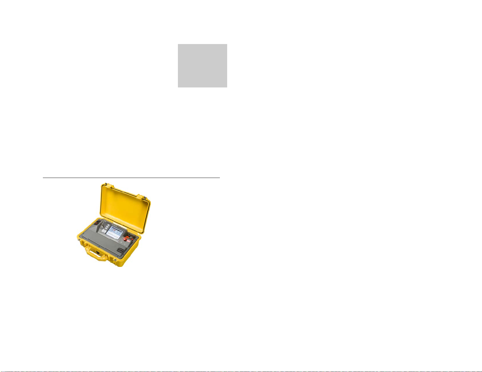
•The DRM-100 instrument is specifically designed for
rough usage and to function reliably in energized
EHV substations where high electrical and magnetic
fields are frequently present.
•The DRM-100 instrument was also designed to
function accurately and reliably with up to 1000
VAC of noise present on the device under test - a
common condition in energized transformer stations.
•Test results are displayed in extra large font on the
bright color LCD screen.
•Membrane switch buttons surround the screen for
setting the test current, test time and for initiating the
test.
•The DRM-100 uses the 4-terminal method of
resistance measurement to eliminate the effects of
lead resistance.

Chapter 1 — Introduction
Page 3
Options and Accessories
DRM-100 accessories
The DRM-100 comes with these standard accessories:
•Current Test Leads
•Potential Test Leads
•Ground lead
•Main input power cord (suitable for location)
•DRM-100 instrument
•User Manual (this document)
The optional accessories:
•Transit case on the wheels for easier transportation
Getting to Know the DRM-100
Page 4
Getting to Know
the DRM-100
This chapter describes the various features, tools, and
screens of the DRM-100, and how to navigate the system.
Front Panel Components
Power Entry Module with Main Switch
Power Entry Module is located on the top left corner of
front panel. Main power switch and fuse holder are
integrated in entry module. The fuse rating is 8A 250
VAC, Type T. The nominal power voltage rating is 100-
Chapter
2
Chapter 2 — Getting to Know the DRM-100
Page 5
240VAC 50/60Hz, without need for adjustment. Do not
cover Power Entry Module with test leads or any other
object and keep it accessible.
Grounding/Earth Terminal
Metal ground/earth binding post is on the right side of
Entry Module for grounding/earth the equipment under
the test.
LCD Screen
LCD screen is installed on the middle of front panel. It
shows test conditions like current, time and measured
resistance.
Buttons
On the left side of LCD screen are 4 membrane buttons.
They are used to select the time and current settings and
to Start or Stop the test.
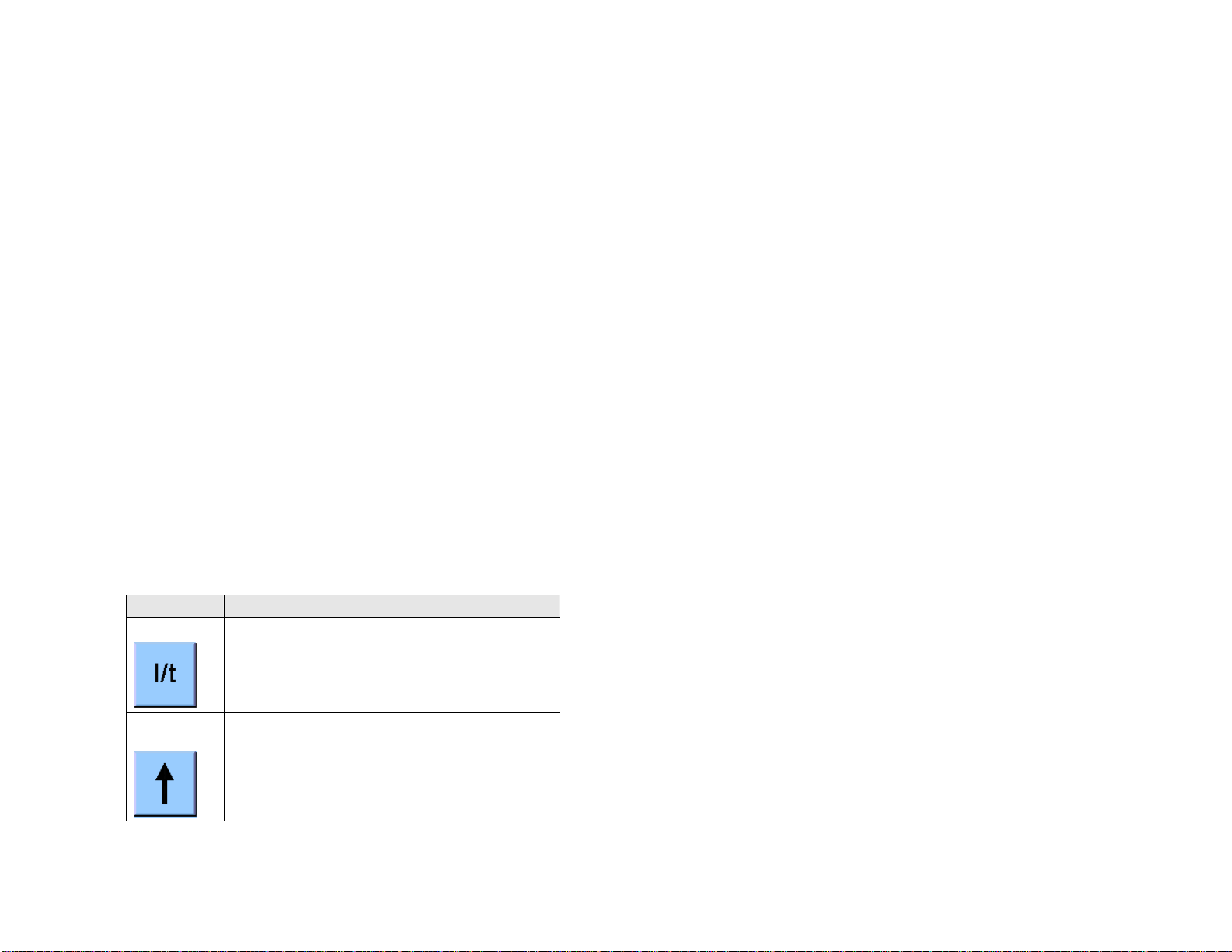
Item Description
I/t Button
I/t button is used to toggle between the current
selection and time selection fields. The selected
field is highlighted with bright yellow color
Up Arrow
button
Up Arrow button is used to increment value of
selected field of current or time. The current can be
incremented in steps of 10A from 10 to 100A. The
time can be incremented from 10 to 60 seconds in
steps of 1 second.
Chapter 2 — Getting to Know the DRM-100
Page 6
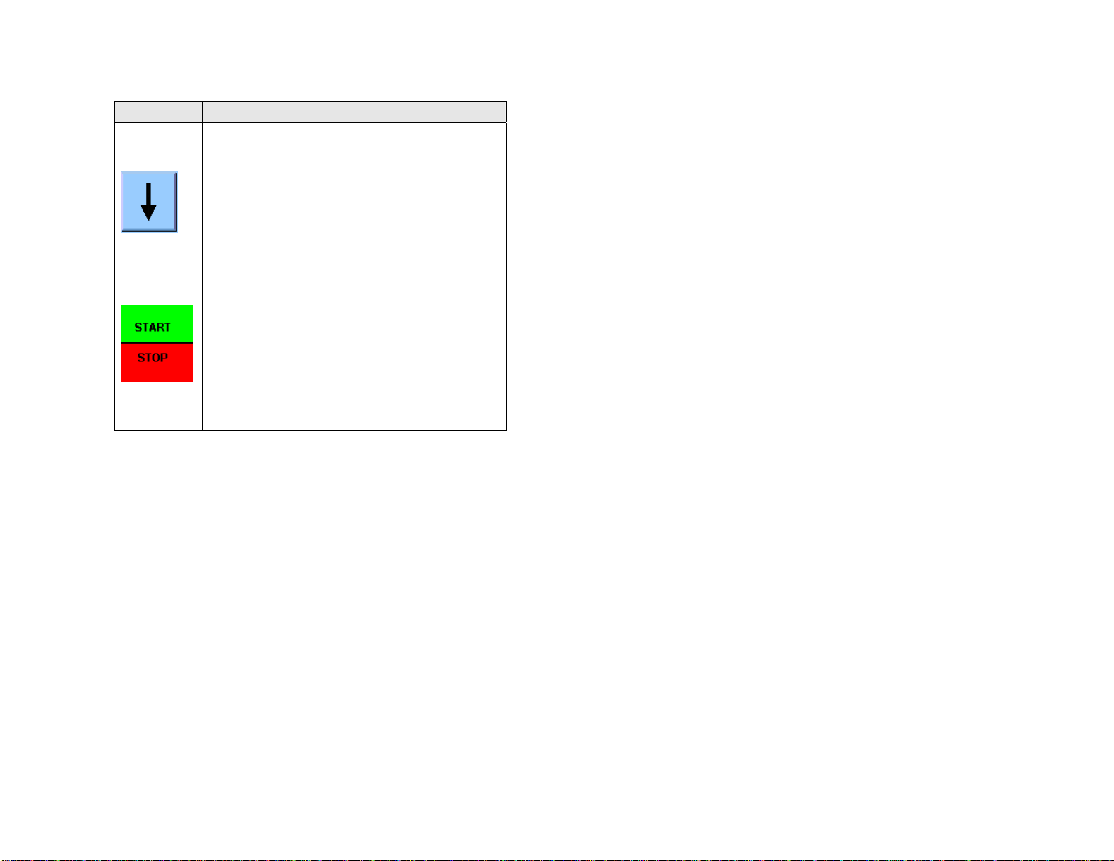
Item Description
Down
Arrow
button
Down Arrow button is used to decrement value of
selected field of current or time. The current can be
decremented in steps of 10A. The time can be
decremented from in steps of 1 second.
START/
STOP
button
The START/STOP push button is bigger than other
three and has a symbol of a set of contacts on it. It
is used to START and STOP the test. When this
button is pressed the output current ramps up over
2 to 3 seconds, holds at the selected current value
and then ramps down to zero over 2 to 3 seconds.
This cycle constitutes the complete timed test
sequence. When the test current reaches the
selected value, the instrument shows the
measured value of resistance. If this button is
pressed in the middle of the test sequence, the
instrument will ramp down the current to zero in 2
to 3 seconds
Current Receptacles
At the top right corner of front panel are two, larger black
and red current sockets. They are marked with positive
and negative symbols and Current Output description.
They are sockets for the current test leads and provide
current output (selected under I-SET field).
Voltage Receptacles
Next to current output receptacles are voltage input
sockets in black and red color. They marked with positive
and negative symbols and resistor symbol. They are
sockets for the potential leads

Chapter 2 — Getting to Know the DRM-100
Page 7
Emergency Stop Button
The large, red, emergency stop, mushroom button is
located below the current output and voltage input
receptacles. It cuts off the output DC test current
immediately (not the instrument main power supply). It is
marked with red highlighted text EMERGENCY STOP.
The button latches in the stop position. To release the
button, twist it clockwise
RS-232 Connector
This connector is used for calibration and testing purposes
only. The user should not attempt to connect to it for any
reason.
Test Leads
These leads consist of two heavy gauge current leads, two
lighter gauge potential leads, and an earth lead. They are
supplied in a separate cable bag. The length and gauge
depend on the purchase options selected.

Chapter 2 — Getting to Know the DRM-100
Page 8
Graphical User Interface
The graphical user interface consists of two pages,
namely:
•Startup page and
•Main page.
The contents of these pages are described below.
Startup Screen
On start up, a window appears with the ADWEL logo,
the instrument name, serial number and firmware
software version. The start up screen also shows
ADWEL’s Address, Telephone and Fax number.

Chapter 2 — Getting to Know the DRM-100
Page 9
Main Screen
Main screen is divided into two areas:
1. Top area is reserved for messages about
instrument status, current selection, test duration
selection, measured current and count-down
timer.
2. Bottom area is reserved to show the bright and
easy-to-read 41/2 digit measured resistance.
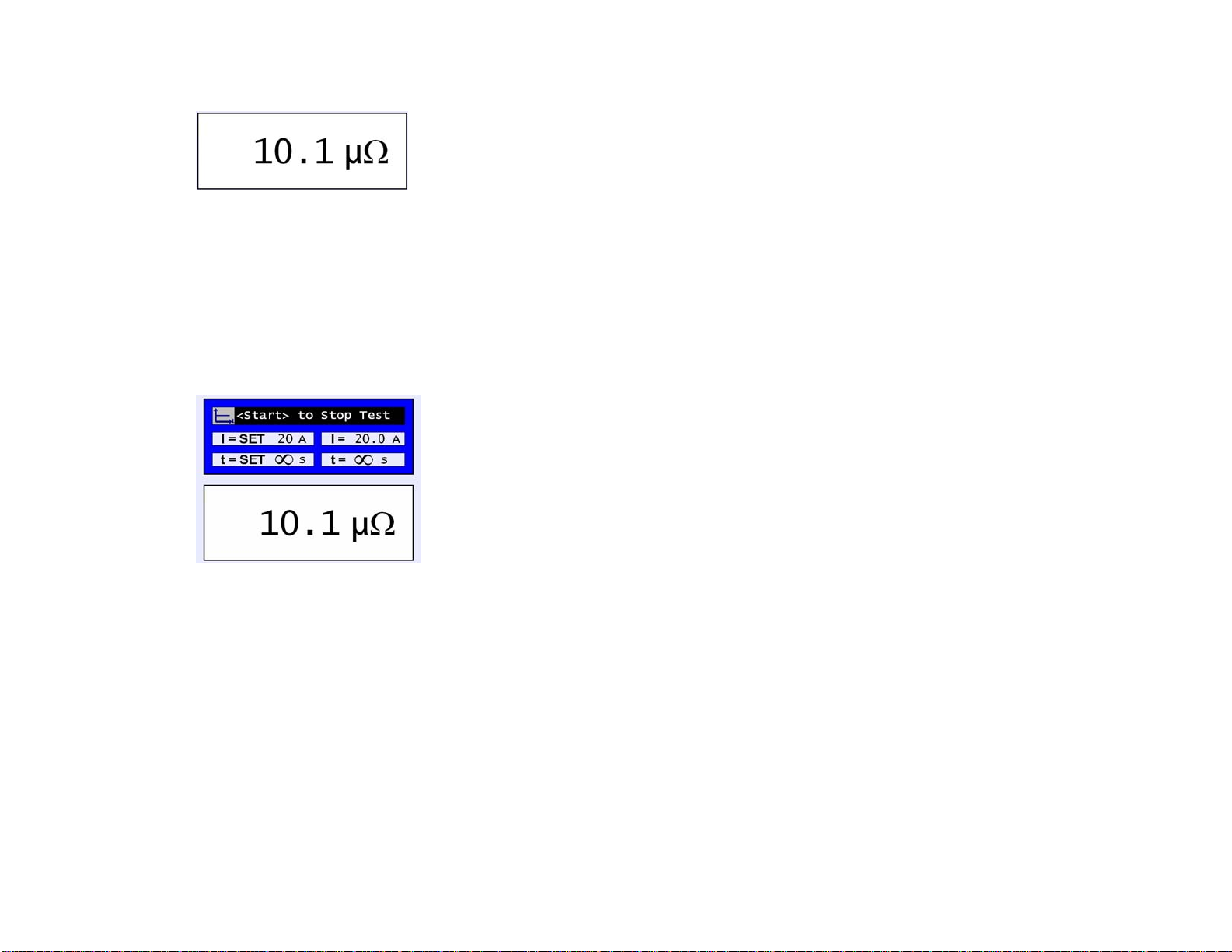
Resistance Displays
The bottom area is reserved to show the resistance
measurement. It shows resistance in micro-ohms (µΩ) or
milli-ohms (mΩ), depending upon the measured value.
The instrument automatically switches between ranges.
The display shows the resistance in 4-1/2 digit format.
Normally this format would limit at a value of 19999,
however a small degree of over-range is usually allowed,
depending on the voltage drop in the test leads.
Chapter 2 — Getting to Know the DRM-100
Page 10
The DRM-100 measures resistance in 3 ranges, which are
auto-selected depending on the test current and
discovered resistance. The ranges are:
0 µΩto 1999.9 µΩfor currents from 10 to 100A
0 mΩto 19.999 mΩfor currents from 10 to 100A
0 mΩto 199.99 mΩfor currents of 10A only
The duration of the test is selectable from 10 to 60
seconds for all currents.
Continuous Resistance Test
The instrument can be set to provide a continuous test
current, so that resistance may be continuously monitored.
This is achieved by setting the test time to continuous (∞).
If this value is selected, the instrument selects a test
current of 20A automatically. The DRM-100 can supply
20A indefinitely. The test is started and stopped by
pressing the START/STOP button.
If the test current is afterwards selected to other than 20A,
the continuous test time is immediately cancelled and
defaulted to 10 seconds.

Chapter 2 — Getting to Know the DRM-100
Page 11
This mode can be used for troubleshooting equipment
under test.
Current versus Resistance Ranges
The maximum voltage that can be measured on the DRM-
100 voltage inputs is slightly over 2V, and it is this that
limits the maximum resistance value that may be read.
This allows measurement of higher resistances at lower
currents. The relationship between the selected test
current and the maximum possible resistance value is
shown below. The maximum value will vary between
instruments and individual measurements and depends
upon the DC offset voltage measured before the
beginning of each test.
10A over 200 mΩ
20A over 100 mΩ
30A over 67 mΩ
40A over 50 mΩ
50A over 40 mΩ
60A over 33 mΩ
70A over 28 mΩ
80A over 25 mΩ
90A over 22 mΩ
100A over 20 mΩ
Table of contents
Popular Measuring Instrument manuals by other brands


Endress+Hauser
Endress+Hauser iTEMP TMT162 operating instructions

PCE Instruments
PCE Instruments PCE-CMM 8 user manual

Rion
Rion UV-15 instruction manual

YOKOGAWA
YOKOGAWA YPP6060 instruction manual

NewMar
NewMar SPM-200 Installation & operation manual

National Instruments
National Instruments PXI-4070 6 1/2 Digit FlexDMM CALIBRATION PROCEDURE