AE-Air HydroTech HRC Series Instruction manual
Installation, Operation, & Maintenance Manual
IOM 787702
Rev. B 3/22
HRC(C,X) High Rise Series
Water Source Heat Pump

HRC(C,X) HIGH RISE SERIES - IOM
2
HRC(C,X) HIGH RISE SERIES –IOM (REV. B 3/22)
COPYRIGHT
AE-Air works to continuously improve its products and as a result, it reserves the right to change design and specifications
without notice.
The warranty may be void unless the Startup & Performance Checklist is completed and returned to the warrantor. If the HVAC
unit is not installed properly, the warranty will be void, as the manufacturer cannot be held accountable for problems that stem
from improper installation.
©2022 AE-Air, 8273 Moberly Lane, Dallas, TX 75227
***WARNING TO INSTALLER, SERVICE PERSONNEL AND OWNER***
Altering the product or replacing parts with non-authorized factory parts voids all warranty or implied warranty and may
result in adverse operational performance and/or a possible hazardous safety condition to service personnel and
occupants. Company employees and/or contractors are not authorized to waive this warning.

HRC(C,X) HIGH RISE SERIES –IOM
HRC(C,X) HIGH RISE SERIES –IOM (REV. B 3/22)
3
TABLE OF CONTENTS
SAFETY CONSIDERATIONS
4-5
MODEL NOMENCLATURE
6-7
GENERAL INFORMATION
8
INTRODUCTION
8
STORAGE
9
SHIPPING & PACKAGE LIST
9-10
UNIT INSPECTION CHECKLIST
11
UNIT DIMENSIONAL DATA
12-15
UNIT PHYSICAL DATA
16
ELECTRICAL DATA
17
INSTALLATION
18-28
CABINET CONFIGURATION
29-32
ELECTRICAL
33
APPLICATION
34-35
CONTROLS
36-41
PERFORMANCE DATA
42
WIRING DIAGRAMS
43-50
CIRCUIT SCHEMATIC
51
STARTUP INSTRUCTIONS
51-52
STARTUP & PERFORMANCE CHECKLIST INSTRUCTIONS
52
MAINTENANCE & SERVICE
53
TROUBLESHOOTING
54-55
SUPPORT/REFERENCE MATERIAL
56
STARTUP & PERFORMANCE CHECKLIST
57
NOTES
58
HRC(C,X) HIGH RISE SERIES - IOM
4
HRC(C,X) HIGH RISE SERIES –IOM (REV. B 3/22)
SAFETY CONSIDERATIONS
1. READ THE ENTIRE MANUAL BEFORE STARTING THE INSTALLATION.
2. These instructions are intended as a general guide and do not supersede national, state, or local codes in any way.
3. Altering the product, improper installation, or the use of unauthorized factory parts voids all warranty or implied warranty
and may result in adverse operation and/or performance or may result in hazardous conditions to service personnel and
occupants. Company employees or contractors are not authorized to waive this warning.
4. This product should only be installed and serviced by a qualified, licensed, and factory authorized installer or service agency.
5. All “kits” and “accessories” used must be factory authorized when modifying this product. Refer and follow instructions
packaged with the kits or accessories when installing.
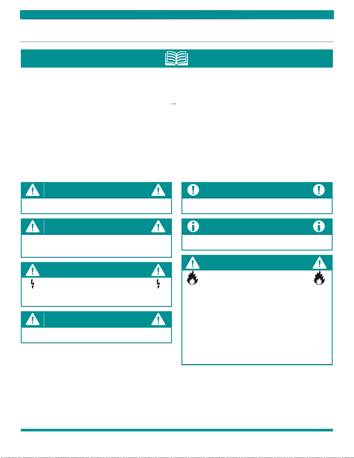
RECOGNIZE THE FOLLOWING SAFETY NOTATIONS THROUGHOUT THIS MANUAL
AND POSTED ON THE EQUIPMENT:
Indicates an imminently hazardous situation which, if not
avoided, will result in death or serious injury.
Indicates a potentially hazardous situation or unsafe
practices that could result in severe personal injury or death
and/or damage to property.
This warning signifies potential electrical shock hazards that
could result in personal injury or death.
The CAUTION symbol indicates a potentially hazardous
situation that may result in minor or moderate injury.
Suggests important procedure steps to insure proper
installation, reliability, or operation.
Used to highlight suggestions, which may result in enhanced
installation, reliability or operation.
Failure to follow safety warnings exactly could result in
dangerous operation, serious injury, death or property
damage.
Improper servicing could result in dangerous operation,
serious injury, death or property damage.
Before servicing, disconnect all electrical power to
the HRC(C,X) water source heat pump.
When servicing controls, label all wires prior to
disconnecting. Reconnect wires correctly.
Verify proper operation after servicing.
HRC(C,X) HIGH RISE SERIES –IOM
HRC(C,X) HIGH RISE SERIES –IOM (REV. B 3/22)
5
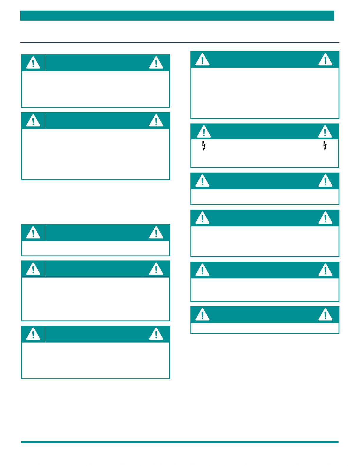
SAFETY CONSIDERATIONS CONTINUED
Mechanical components and filters can become clogged with
dirt and debris, which can cause damage to the system.
The manufacturer does not warrant equipment subjected to
abuse. Construction debris can void warranties and liability
for equipment failure, personal injury, and property damage.
Material in this shipment has been inspected at the factory
and released to the transportation agency in good condition.
When received, a visual inspection of all cartons should be
made immediately. Any evidence of rough handling or
apparent damage should be noted on the delivery receipt in
the presence of the carrier’s representative. If damage is
found, a claim should be immediately filed against the carrier.
These models are designed for indoor installation only.
Installation of this equipment, wiring, ducts, and any related
components must conform to current agency codes, state
laws, and local codes. Such regulations take precedence over
general instructions contained in this manual.
DO NOT USE FOR HEATING AND COOLING BUILDINGS OR
STRUCTURE UNDER CONSTRUCTION!
Improper installation, adjustment, alteration, service, or
maintenance can cause property damage, personal injury or
loss of life. Refer to the user’s information manual provided
with this water source heat pump. Installation and materials,
service must be performed by a qualified installer, or service
agency.
Installation and service must be performed by a licensed
professional installer (or equivalent), or service agency.
Attempting to install or repair this unit without such
background may result in product damage, personal injury or
death.
These instructions are intended as an aid to qualified,
licensed service personnel for proper installation, adjustment
and operation of this unit. Read these instructions thoroughly
before attempting installation or operation. Failure to follow
these instructions may result in improper installation,
adjustment, service or maintenance possibly resulting in fire,
electrical shock, property damage, personal injury or death.
Disconnect all power before servicing. Failure to do so may
result in property damage, personal injury, or death.
Use care when handling compressors. Some surfaces could
be hot!
Compressors should NOT be used to evacuate the air
conditioning system. Vacuums this low can cause internal
electrical arcing resulting in a damaged or failed
compressor.
The unit must be permanently grounded. Failure to do so
can cause electrical shock resulting in severe personal
injury or death.
“USE COPPER SUPPLY WIRES ONLY!”
HRC(C,X) HIGH RISE SERIES - IOM
6
HRC(C,X) HIGH RISE SERIES –IOM (REV. B 3/22)
SAFETY CONSIDERATIONS CONTINU ED
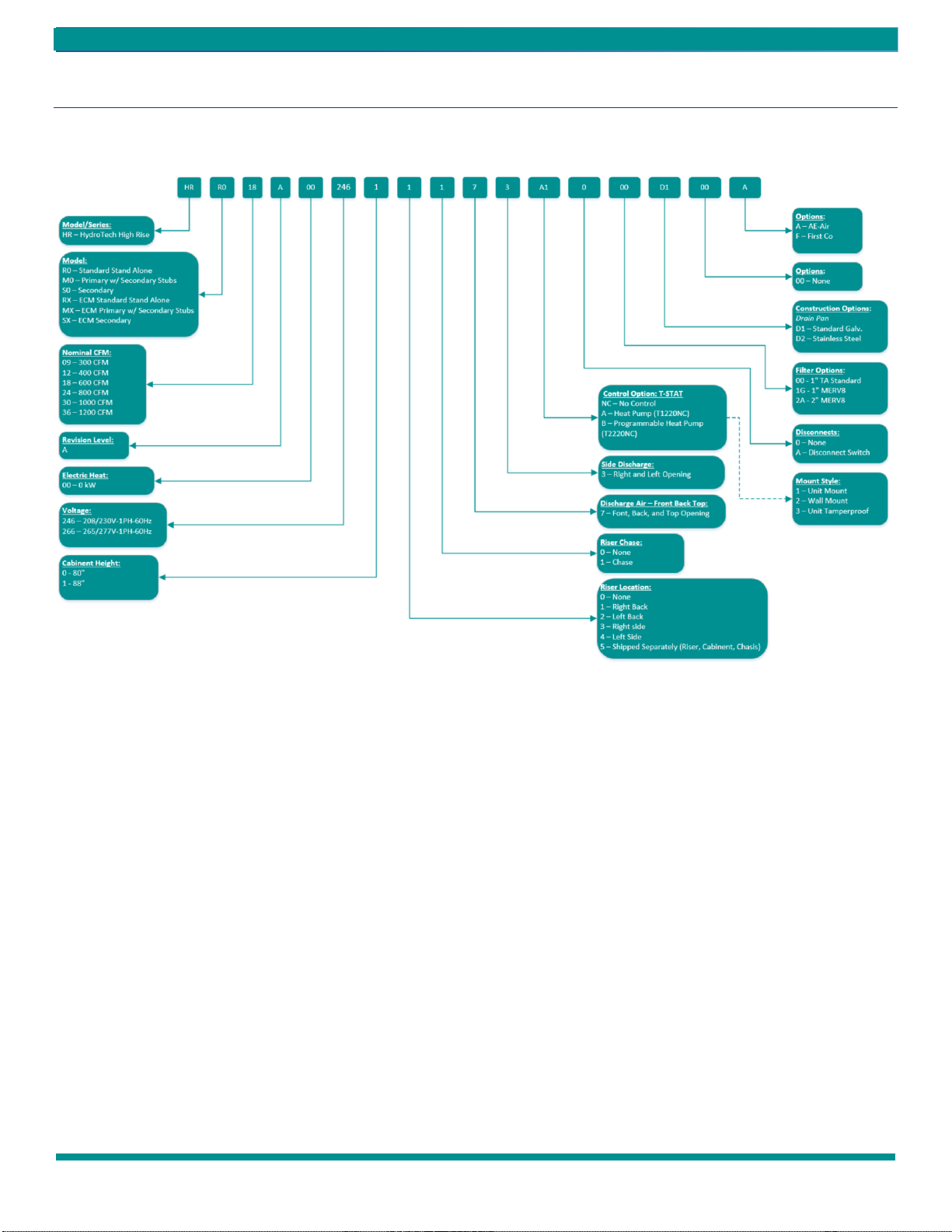
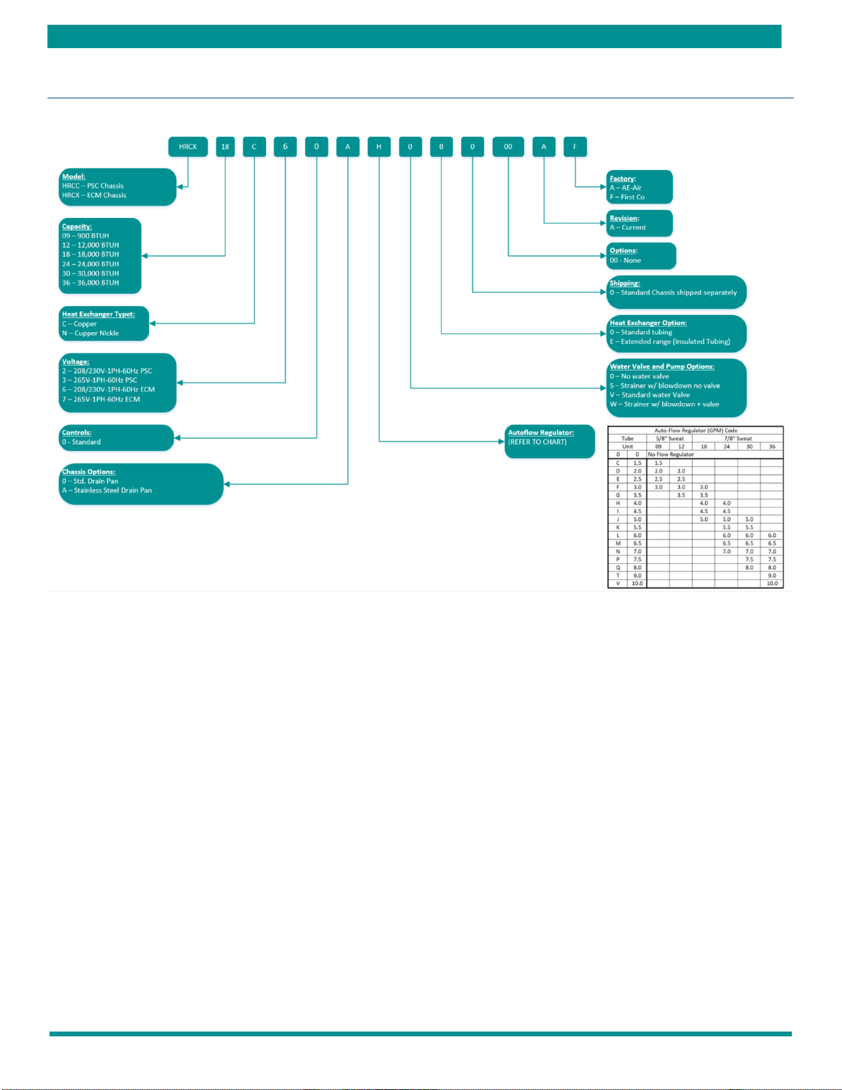
MODEL NOMENCLATURE
FIGURE 1 –Cabinet Model Nomenclature
HRC(C,X) HIGH RISE SERIES –IOM
HRC(C,X) HIGH RISE SERIES –IOM (REV. B 3/22)
7
MODEL NOMENCLATURE CONTINUED
FIGURE 2 –Chassis Model Nomenclature

HRC(C,X) HIGH RISE SERIES - IOM
8
HRC(C,X) HIGH RISE SERIES –IOM (REV. B 3/22)
GENERAL INFORMATION
DO NOT use these units as a source of heating or cooling
during the construction process. Mechanical components
and filters can become clogged with dirt and debris, which
can cause damage to the system.
The manufacture does not warrant equipment subjected
to abuse.
Before servicing equipment, ALWAYS turn off all power to
the unit. There may be more than one disconnect switch.
Electrical shock can cause injury or death.
Clear surrounding area of all tools, equipment, and debris
before operating this unit.
These instructions are provided for the installation of the
HRC(C,X) high rise water source heat pump specifically. For
any other related equipment, refer to the appropriate
manufacturer’s instructions.
This water source heat pump must never be operated
under any circumstances without an air filter in place.
Material in this shipment has been inspected at the
factory and released to the transportation agency in
good condition. When received, a visual inspection of all
cartons should be made immediately. Any evidence of
rough handling or apparent damage should be noted on
the delivery receipt in the presence of the carrier’s
representative. If damage is found, a claim should be
immediately filed against the carrier.
The HRC(C,X) high rise water source heat pump is designed
for indoor installation only. Installation of this equipment,
wiring, ducts, and any related components must conform
to current agency codes, state laws, and local codes. Such
regulations take precedence over general instructions
contained in this manual
Extreme caution must be taken that no internal damage
will result from screws that are drilled into the cabinet.
INTRODUCTION
The HydroTech HRC(C,X) series water to air heat pump
provide the best combination of performance, efficiency
and reliability in a compact form factor. The HRC(C,X)
series comes standard with PSC blower motors. It is also
available with ECM blower motors for high efficiency and
comfort. The heat pump features double compressor
vibration isolation for quiet operation, easy to remove
blower housing for quick service
All HRC(C,X) models are certified to AHRI ISO Standard
13256-1. The HRC(C,X) models are designed to operate
with fluid temperatures between 50°F to 110°F in
cooling mode and 50°F to 90°F in heating mode for
continuous operation. For operation below 50°F or
above 90°F entering water temperature, extended range
(insulated tubing) option is needed, and sufficient water
flow is required to prevent freezing. Antifreeze solution
is required for any application with entering water below
50 degree F.
Cooling Tower/Boiler and Geo Thermal applications
should have sufficient antifreeze solution when required
to protect against extreme conditions and equipment
failure. Frozen water coils are not covered under
warranty.
These installation instructions are intended as a general
guide only, for use by an experienced, qualified contractor.
Do not use this water source heat pump during any phase
of construction.
DO NOT use these units as a source of heating or cooling
during the construction process. Mechanical components
and filters can become clogged with dirt and debris, which
can cause damage to the system.
The manufacture does not warrant equipment subjected
to abuse.
HRC(C,X) HIGH RISE SERIES –IOM
HRC(C,X) HIGH RISE SERIES –IOM (REV. B 3/22)
9
STORAGE
Equipment should be stored in a clean dry, conditioned
area with maximum temperatures up to 120°F [48.89°C]
and minimum temperatures to 32°F [0°C]. Units should be
stored upright and in an indoor environment. It is
recommended to leave packaging on the unit until the
installation is to begin. Store or move chassis in an upright
position at all times. If stacking of chassis is required, do not
stack more than two units high.
Store cabinets how they are shipped (horizontal or
vertical), keeping them crated and on their pallets for
protection. Cabinets with risers should not be stacked
more than three units high. Failure to follow these
instructions may result in improper installation,
adjustment, service or maintenance, property damage,
personal injury or death.
DO NOT operate these units during the construction
process. Mechanical components and filters could become
clogged with dirt and debris, which can cause damage to the
system.
The manufacturer does not warrant equipment subjected
to abuse.
SHIPPING & PACKAGE LIST
Material in this shipment has been inspected at the factory
and released to the transportation agency in good
condition. When received, a visual inspection of all cartons
should be made immediately. Any evidence of rough
handling or apparent damage should be noted on the
delivery receipt in the presence of the carrier’s
representative. If damage is found, a claim should be
immediately filed against the carrier.
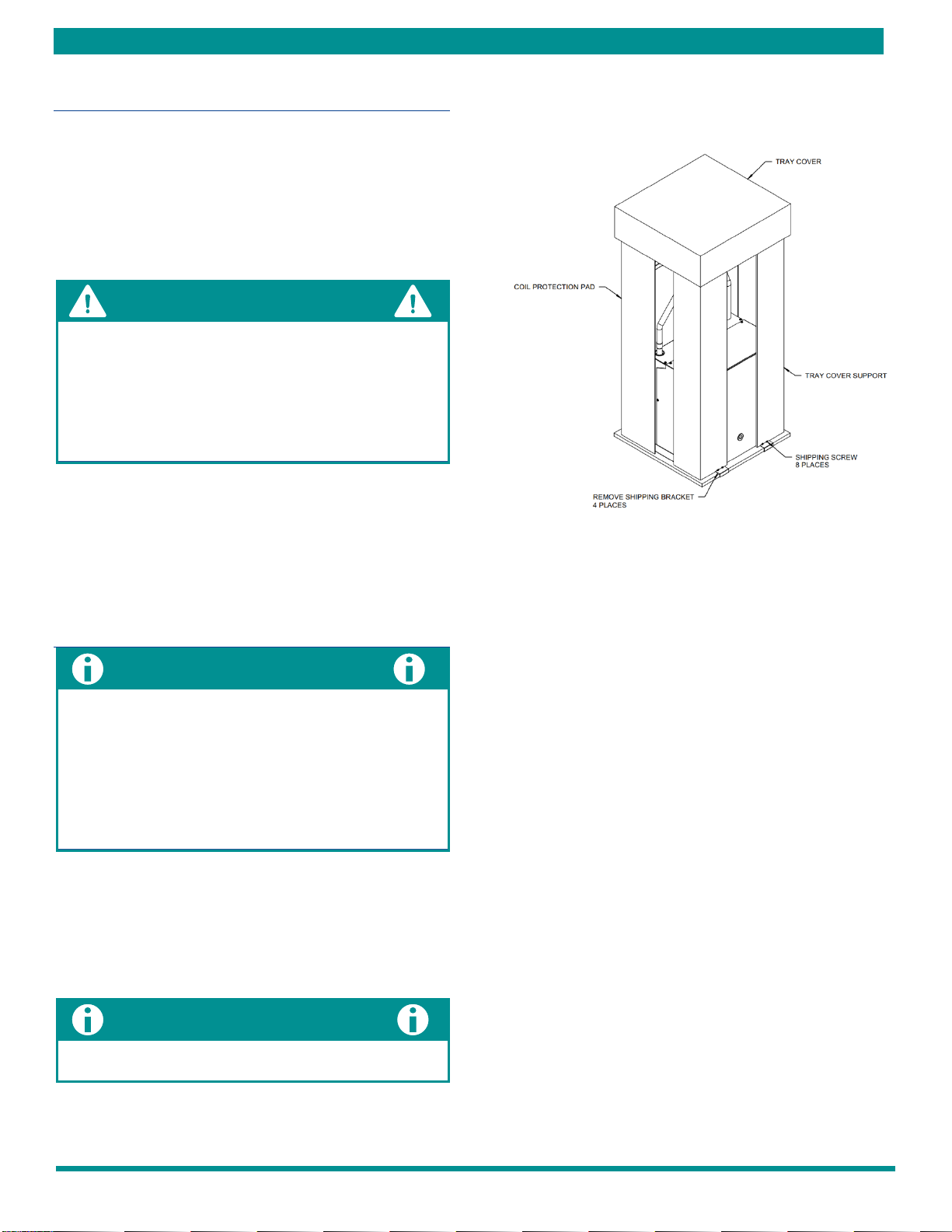
SHIPPING INSTRUCTIONS
HRC(C,X) chassis must remain in the upright position as
seen in FIGURE 3 –Standard Packaging throughout the
shipping and handling process to maintain a proper level of
oil in the compressor. HRC(C,X) cabinets are shipped in the
horizontal or vertical position.
Shrink-wrap is located around the unit for protection.
Remove before installation.
FIGURE 3 –Standard Packaging
PACKAGE LIST
The units will be shipped with the following items:
1- HRC(C,X) high rise unit:
A- Shipping brackets
a. Screws
2- Literature package
A- IOM - Installation & Operations Manual
Check the unit for shipping damage; if found, immediately
contact the last carrier.
HRC(C,X) HIGH RISE SERIES - IOM
10
HRC(C,X) HIGH RISE SERIES –IOM (REV. B 3/22)
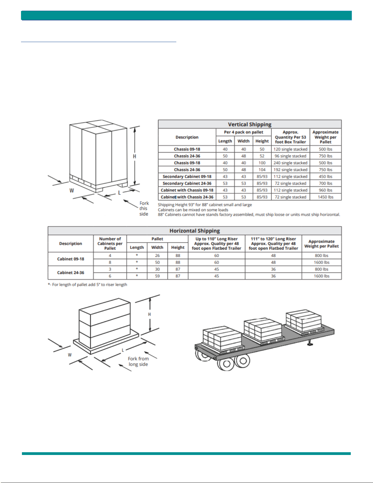
SHIPPING & PACKAGE LIST
Units Are Shipped FOB Factory
Chassis can be shipped 2 ways.
1. Upright in carton 4 per pallet, see FIGURE 4 –Shipping
Options.
2. Upright inside cabinet (risers shipped separate or
customer supplied) 4 per pallet, see FIGURE 4 –Shipping
Options
FIGURE 4 –Shipping Options
HRC(C,X) HIGH RISE SERIES –IOM
HRC(C,X) HIGH RISE SERIES –IOM (REV. B 3/22)
11
UNIT INSPECTION CHECKLIST
Complete the inspection procedures below before
preparing unit for installation:
1) Visually inspect unit for any shipping damage. Damage
must be reported immediately to the shipping
company to make a claim.
2) Ensure that the carrier makes proper notation of any
shortages or damage on all copies of the freight bill
and completes a common carrier inspection report.
3) Verify that unit nameplates on the data label match
the sales order or bill of lading (including, unit
configuration, size and voltage).
4) Immediately before installation, remove unit front
panel and verify that all electrical connections are
tight and that there are no loose wires.
5) Check to make sure that the refrigerant piping is free
from any kinks and there is no interference between
unit piping and sheet metal or electrical wires.
6) Check that the blower spins freely within the housing
and that there are no obstructions between the wheel
and housing. The wheel can sometimes come loose in
shipping.
7) Ensure that the evaporator distributor tubes are not
touching one in another and that they are over the
drain pan.
8) Check the air-coil fins for any damage during shipping.
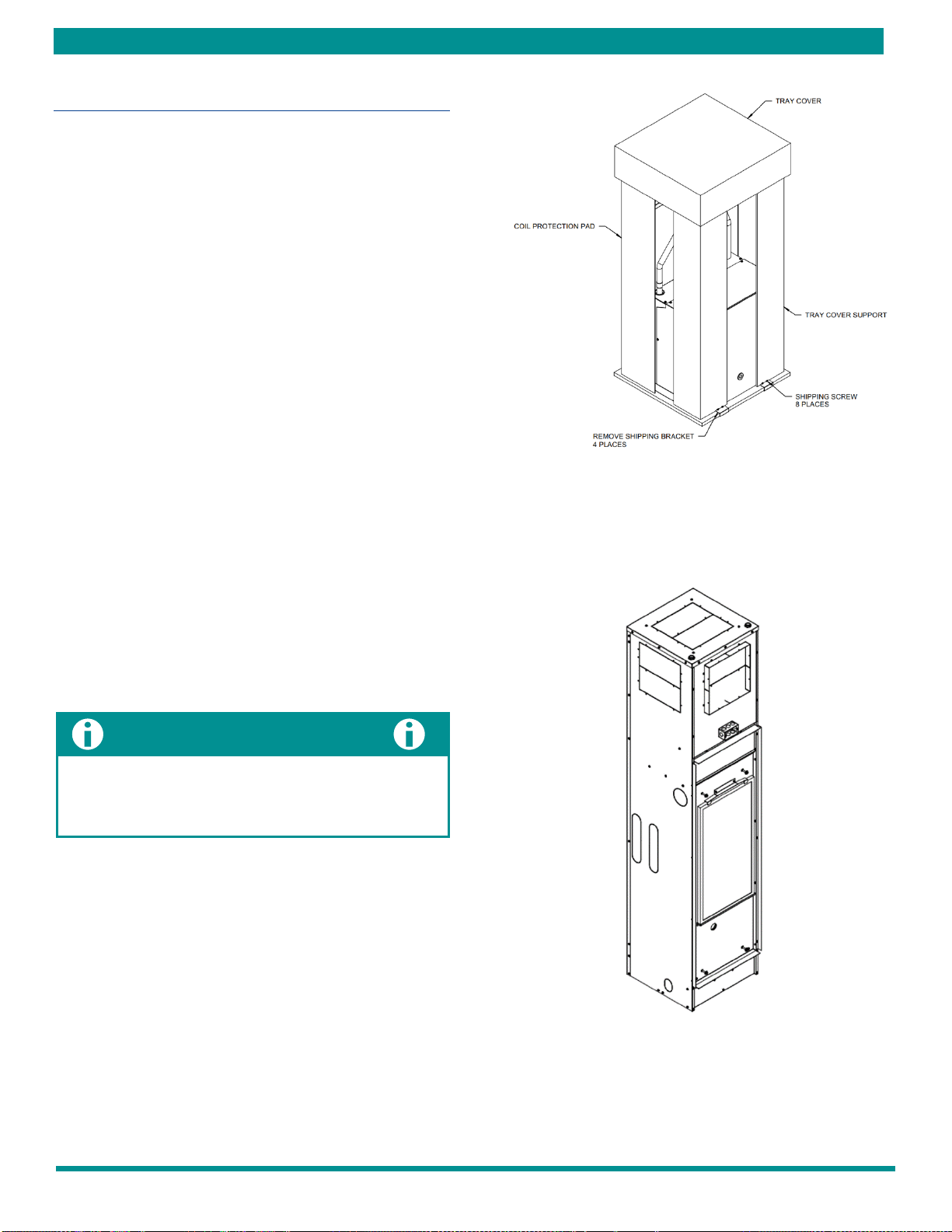
9) Ensure that the shipping screws are removed from
the unit. Refer to FIGURE 5 –Standard Packaging with
Brackets - Chassis for more information.
Check the unit nameplate for correct voltage with the
plans before installing the equipment. Also, make sure all
electrical ground connections are made in accordance
with local code.
FIGURE 5–Standard Packaging with Brackets –Chassis
FIGURE 6 –Standard Cabinet

HRC(C,X) HIGH RISE SERIES - IOM
12
HRC(C,X) HIGH RISE SERIES –IOM (REV. B 3/22)
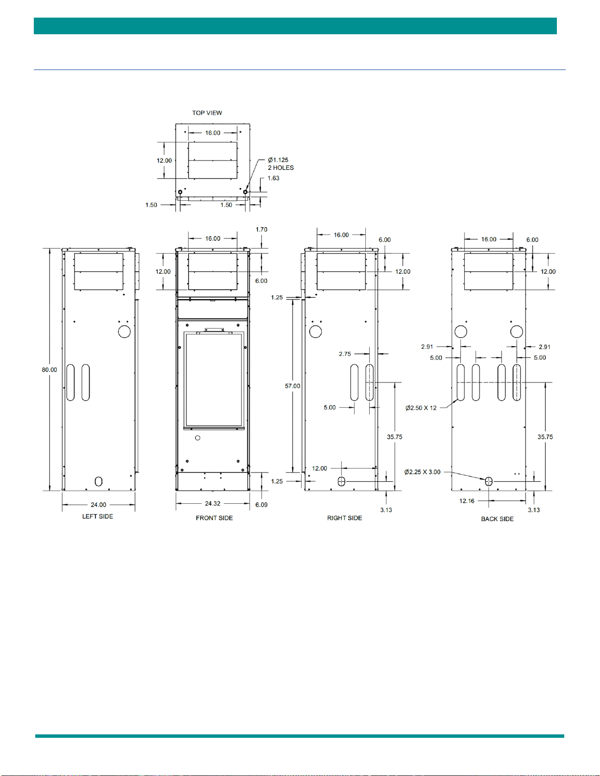
UNIT DIMENSIONAL DATA
FIGURE 7 –Unit Dimensions

HRC(C,X) HIGH RISE SERIES –IOM
HRC(C,X) HIGH RISE SERIES –IOM (REV. B 3/22)
13
UNIT DIMENSIONAL DATA CONTINUED
FIGURE 8 –Unit Dimensions

HRC(C,X) HIGH RISE SERIES - IOM
14
HRC(C,X) HIGH RISE SERIES –IOM (REV. B 3/22)
UNIT DIMENSIONAL DATA CONTINUED
FIGURE 9 –Unit Dimensions
HRC(C,X) HIGH RISE SERIES –IOM
HRC(C,X) HIGH RISE SERIES –IOM (REV. B 3/22)
15
UNIT DIMENSIONAL DATA CONTINUED
FIGURE 10 –Unit Dimensions
HRC(C,X) HIGH RISE SERIES - IOM
16
HRC(C,X) HIGH RISE SERIES –IOM (REV. B 3/22)
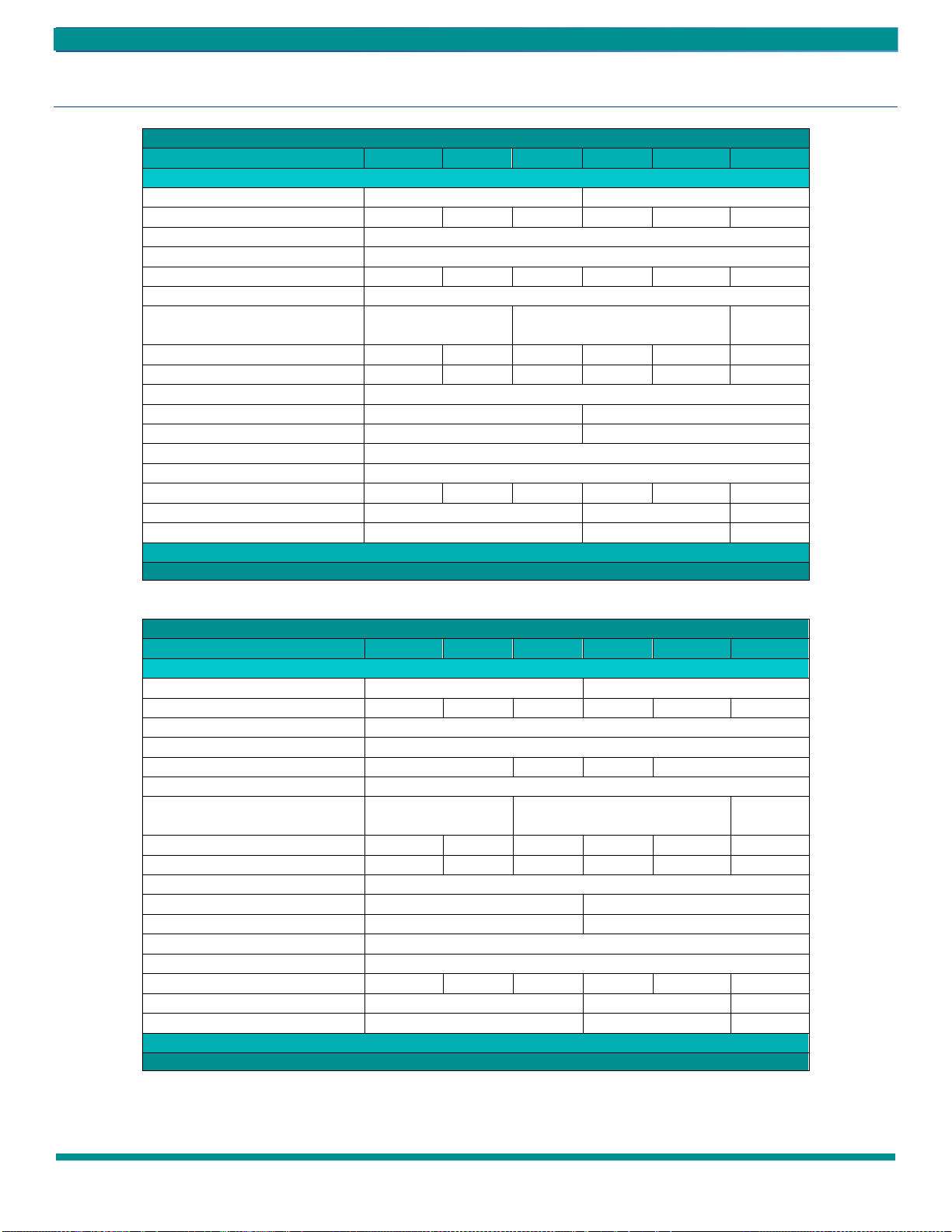
UNIT PHYSICAL DATA
PHYSICAL DATA
HRCC MODELS
HRCC09
HRCC12
HRCC18
HRCC24
HRCC30
HRCC36
UNIT INFORMATION
Compressor Type (Qty)
Rotary (1)
Scroll (1)
Factory Charge (R410A) lbs. [oz]
1.7 [27]
2.7 [43]
2.7 [43]
3.7 [59]
3.7 [59]
3.6 [57]
Motor (Qty)
1
Fan Motor Type
PSC
Fan Motor HP [kW]
1/12 [.06]
1/10 [.07]
1/4 [.18]
1/6 [.12]
1/2 [.37]
1/2 [.37]
Blower (Qty)
1
Blower Wheel Size (D x W) in. [cm]
6.75 x 7 [17.15 x
17.78]
9 x 7 [22.86 x 17.78]
10 x 8 [25.4
x 20.32]
Hose Size (in)
1/2
1/2
3/4
1
1
1
COAX Volume (US Gallons)
0.116
0.116
0.144
.544
.544
.544
Condensate Connection O.D. (in)
1-1/8
Air Coil Dimension (H x W) in. [cm]
28 x 14 [11.0 x 5.5]
30 x 18 [11.8 x 7.1]
Filter Size (H x W) in. [cm]
30 x 16 [11.8 x 6.3]
32 x 20 [12.6 x 7.9]
Filter (Qty)
1
Operating Weight
Weight
Chassis lb. [kg]
125[57]
128[58]
131[59]
182[83]
185[84]
188[85]
80” Cabinet lb. [kg]
128[58]
173[78]
175[79]
88” Cabinet lb. [kg]
143[65]
188[85]
190[86]
Table 1 –Physical Data PSC
PHYSICAL DATA
HRCX MODELS
HRCX09
HRCX12
HRCX18
HRCX24
HRCX30
HRCX36
UNIT INFORMATION
Compressor Type (Qty)
Rotary (1)
Scroll (1)
Factory Charge (R410A) lbs. [oz]
1.7 [27]
2.7 [43]
2.7 [43]
3.7 [59]
3.7 [59]
3.6 [57]
Motor (Qty)
1
Fan Motor Type
ECM
Fan Motor HP [kW]
1/4 [.18]
1/3 [.25]
1/3 [.25]
1/2 [.37]
Blower (Qty)
1
Blower Wheel Size (D x W) in. [cm]
6.75 x 7 [17.15 x
17.78]
9 x 7 [22.86 x 17.78]
10 x 8 [25.4
x 20.32]
Hose Size (in)
1/2
1/2
3/4
1
1
1
COAX Volume (US Gallons)
0.116
0.116
0.144
.544
.544
.544
Condensate Connection O.D. (in)
1-1/8
Air Coil Dimension (H x W) in. [cm]
28 x 14 [11.0 x 5.5]
30 x 18 [11.8 x 7.1]
Filter Size (H x W) in. [cm]
30 x 16 [11.8 x 6.3]
32 x 20 [12.6 x 7.9]
Filter (Qty)
1
Operating Weight
Weight
Chassis lb. [kg]
125[57]
128[58]
131[59]
182[83]
185[84]
188[85]
80” Cabinet lb. [kg]
128[58]
173[78]
175[79]
88” Cabinet lb. [kg]
143[65]
188[85]
190[86]
Table 2 –Physical Data ECM
HRC(C,X) HIGH RISE SERIES –IOM
HRC(C,X) HIGH RISE SERIES –IOM (REV. B 3/22)
17
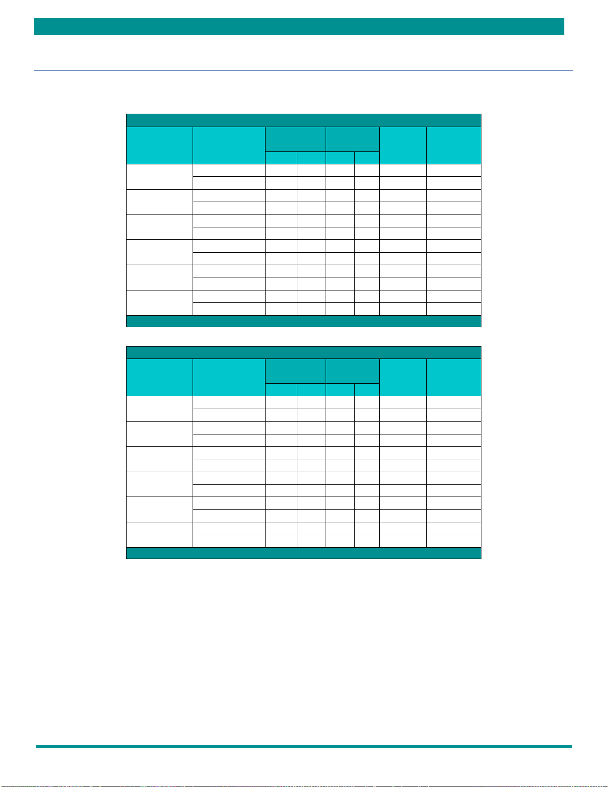
ELECTRICAL DATA
ELECTRICAL DATA PSC
MODEL
NUMBER
VOLTAGE-PH-HZ
COMPRESSOR
BLOWER
MOTOR
MIN.
CIRCUIT
AMPACITY
MAX.
CIRCUIT
PROTECTION
RLA
LRA
FLA
HP
HRCC09
208/230-1-60
3.7
22
0.6
1/12
6
15
265-1-60
3.5
22
0.7
1/15
6
15
HRCC12
208/230-1-60
4.7
25
0.65
1/10
7
15
265-1-60
4.2
22
0.65
1/10
6
15
HRCC18
208/230-1-60
7
38
1.4
1/4
11
15
265-1-60
6
30
1.4
1/4
9
15
HRCC24
208/230-1-60
10.9
62.9
1.6
1/6
16
25
265-1-60
9
54
1.4
1/6
13
20
HRCC30
208/230-1-60
12.8
67.8
3.1
1/2
20
30
265-1-60
11.2
60
2.7
1/2
17
25
HRCC36
208/230-1-60
15.4
82.6
3.1
1/2
23
35
265-1-60
12.2
72
2.7
1/2
18
30
Table 3 –Electrical Data PSC
ELECTRICAL DATA ECM
MODEL
NUMBER
VOLTAGE-PH-HZ
COMPRESSOR
BLOWER
MOTOR
MIN.
CIRCUIT
AMPACITY
MAX.
CIRCUIT
PROTECTION
RLA
LRA
FLA
HP
HRCX09
208/230-1-60
3.7
22
2.3
1/4
7
15
265-1-60
3.5
22
2.3
1/4
7
15
HRCX12
208/230-1-60
4.7
25
2.3
1/4
9
15
265-1-60
4.2
22
2.3
1/4
8
15
HRCX18
208/230-1-60
7
38
2.8
1/3
12
15
265-1-60
6
30
2.6
1/3
11
15
HRCX24
208/230-1-60
10.9
62.9
2.8
1/3
17
25
265-1-60
9
54
2.6
1/3
14
20
HRCX30
208/230-1-60
12.8
67.8
4.1
1/2
21
30
265-1-60
11.2
60
3.6
1/2
18
25
HRCX36
208/230-1-60
15.4
82.6
4.1
1/2
24
35
265-1-60
12.2
72
3.6
1/2
19
30
Table 4 –Electrical Data ECM

HRC(C,X) HIGH RISE SERIES - IOM
18
HRC(C,X) HIGH RISE SERIES –IOM (REV. B 3/22)
INSTALLATION
REQUIREMENTS
Follow manufacturer’s installation instructions, as well as
local and municipal building codes.
INSTALLATION PRECAUTIONS
Always wear all appropriate personal protection
Equipment when installing and servicing these units.
Use multiple people when moving and installing these
units. Failure to do so could result in injury or death.
Contact with metal edges and corners can result injury.
Protective gloves should be worn when handling.
Exercise caution when installing and servicing unit.
Observe the following precautions for typical installation:
Always use proper tools and equipment.
No wiring or any work should be attempted without
first ensuring the unit is completely disconnected from
the power source and locked out. Also, verify that a
proper permanent and uninterrupted, ground
connection exists prior to energizing power to the
unit.
Review unit nameplate and wiring diagram for proper
voltage and control configurations. This information
may vary from unit to unit.
When the unit is in operation components are rotating at
high speeds and caution should be taken.
When soldering and brazing, it is recommended to have a
fire extinguisher readily available. When soldering and
brazing close to valves or sensitive components, heat
shields or wet rags are required to prevent damage to the
valves or components.
Insulation is installed in the unit to provide a barrier
between varying atmospheres outside and within the unit.
If insulation is damaged condensation can occur and can
lead to corrosion, component failure, and possible
property damage. Damaged insulation must be repaired
prior to the operation of the unit. Insulation will lose its
effectiveness and value when wet, torn, separated, and/or
damaged.
When servicing this equipment, because of high pressures,
make sure the reversing valve, expansion device, filter
drier and other components are specifically designed for
R-410A refrigerant.
ONLY USE service equipment specifically designated for
use with R-410A.
R-410A can become combustible if mixed with air at
elevated temperature and/or pressure. Failure to follow
this warning could result in property damage and personal
injury or death.
Do not operate this equipment without an air filter.
HRC(C,X) HIGH RISE SERIES –IOM
HRC(C,X) HIGH RISE SERIES –IOM (REV. B 3/22)
19
INSTALLATION CONTINUED
RISER & CABINET INSTALLATION
Risers can be ordered loose, not attached to the cabinet, and shipped in bulk. Entire riser stacks can be assembled, pressure
tested, flushed, and filled before setting cabinets. Insulate all drain risers and insulate all tubing for extended range applications
(operation below 60 degrees F) or if condensation will occur on riser tubes. Do not construct walls until cabinets are installed
and set.
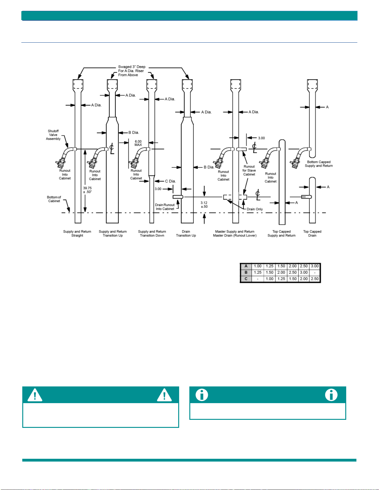
Supply and return risers can be straight, transition up, transition down, bottom capped, or top capped. Drain risers can be
straight, transition up, or top capped. All drain risers and extended range (operation below 50 ºF entering water temperature)
supply and return risers need insulation. See FIGURE 12 –Riser Identification
If filled risers are in unconditioned space, care must be
taken to prevent freezing or condensation to avoid
damage to risers and building.
Risers can be in 4 positions. Supply (S) riser will always be
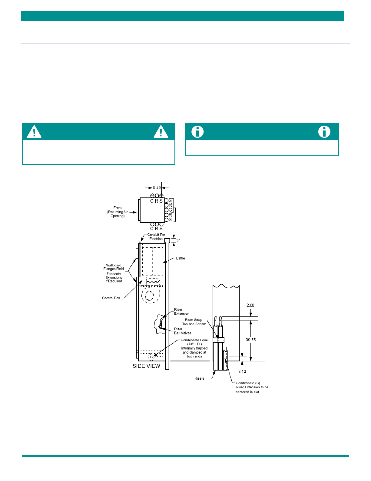
closest to a corner. FIGURE 11 –Cabinet
FIGURE 11 –Cabinet
HRC(C,X) HIGH RISE SERIES - IOM
20
HRC(C,X) HIGH RISE SERIES –IOM (REV. B 3/22)
INSTALLATION CONTINUED
RISER & CABINET INSTALLATION
FIGURE 12 –Riser Identification
These units are for indoor installation ONLY!
Do not locate unit in areas subject to freezing temperatures or where high humidity levels could cause cabinet condensation.
Locate the unit in an area that provides minimum clearance accesses.
Refer to Table 1 –Unit Dimensional Data and Table 2 –Unit Dimensional Data Continued for detailed information on unit
dimensional sizes. Consider all additional clearances needed for water connections, electrical connections, duct connections
and sufficient return airflow.
Do not use soft, low temperature solders like 50-50, 60-40
or 85-15. With copper expansion and contraction, this type
of bond will fail.
Expansion loop design and placement is a function of and
best prescribed by consulting and design engineers.
DRAIN CONNECTION
1/4" (6.4mm) PITCH TOWARD
DRAIN FROM DRAINAGE
Riser Transition Diameters
This manual suits for next models
13
Table of contents
Other AE-Air Heat Pump manuals

Popular Heat Pump manuals by other brands


Dimplex
Dimplex LA 6MR Installation and operating instrictions

ACD
ACD FXD-ACD36 owner's manual

Daikin
Daikin ALTHERMA User reference guide

Bulldog Security
Bulldog Security SKV008 Installation operation & maintenance

Panasonic
Panasonic WH-ADC0916G9E8 Service manual

American Standard
American Standard 4A6H4018N installation guide