AEBI MEYER DIAMOND EDGE User manual

Form No. 1-1241
April 2022
Assembly Instructions
Standard Operating System with Hands Free Plowing
Includes: 41680
© 2022 Printed in the U.S.A.
18513 Euclid Ave. • Cleveland, Ohio 44112-1084
Phone 216-486-1313 www.meyerproducts.com

Table of Contents
General Information.........................................................................................................................................................................................................................1
Black Iron Parts Lists.....................................................................................................................................................................................................................2-3
Moldboard Parts List ........................................................................................................................................................................................................................4
E73 Hydraulics ....................................................................................................................................................................................................................................5
Standard Operating System Wiring............................................................................................................................................................................................6
Plow Assembly & Adjustments.................................................................................................................................................................................................7-8
Mounting Plow...................................................................................................................................................................................................................................9
Dismounting Plow ......................................................................................................................................................................................................................... 10
Pre-Delivery Inspection................................................................................................................................................................................................................ 11
Registration ...................................................................................................................................................................................................................................... 11
(1)
Please visit our website to nd our most updated technical information; including installation instructions, user manuals, parts
diagrams, EZ Troubleshooter, and more.
Please see your owner’s manual for Pre-Season, Post-Season, and General Maintenance.
www.meyerproducts.com
NOTICE:NOTICE: Meyer Products LLC reserves thje right, under its continuing product imporvement program, to change construction, design, details,
specications, and prices without notice or without incurring any obligation. Meyer Products LLC assumes no responsibility for installations not
made in accordance with these instructions.
GENERAL INFORMATION
Always disconnect battery prior to installation.
SAFETY PRECAUTIONS should be used when Quik Lift® is in a RAISED position.
LOWER plow to the ground when vehicle is PARKED.
OVERHAUL and SERVICE information is covered on separate instructions.
Note:
1. Connect ground cable to negative side of battery for a solid connection to ground.
2. Route all cables away from moving engine parts, Manifolds, and sharp sheet metal.
3. For weather protection, coat all connections with Meyer Dielectric Grease Part No. 15632
4. The vehicle must be equipped with a “Heavy Duty Battery” (70 Amp, Hr. Min.), 550 C.C.A. and“Alternator” (60 Amp. Min.) to obtain
maximum performance.
5. Follow these instructions explicitly. Warranty does not apply to a Meyer product which has been negligently or improperly
assembled or installed.
TORQUE CHART FOOT
Pliers
1/2" socket
1/2" box wrench
9/16" box wrench
9/16" socket
3/4" box wrench
15/16" box wrench
15/16" deep well socket
Bolt Nut Size Gr. 2 Gr. 5 Gr. 8
1/4-20 4-5
5/16-18 9-11
3/8-16 17-20 26-29
7/16-14 42-46 60-66
1/2-13 64-72 99-100
5/8-11 127-141 179-198
Tool List for Plow Assembly
(2)
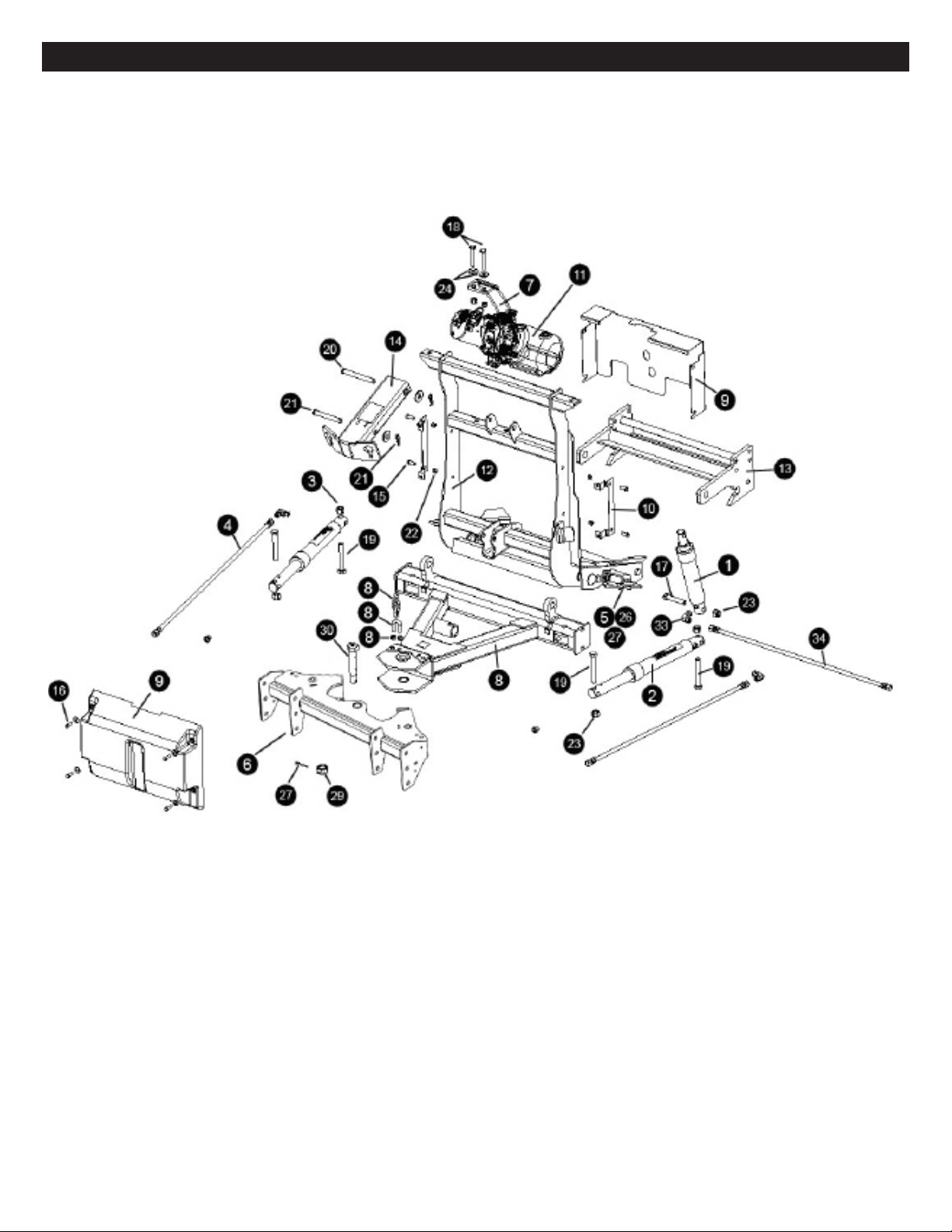
Black Iron Parts List

Black Iron Parts List
(3)
Item Part QTY Description
41620 1 DE SOS E73 7.5-9.0
1 05818 1 Lift Ram 1.75 x 8”
07772 1 • L.H. Ram with Hose & Fittings
2 05887 1 •• Ram (1-1/2” x 10”)
3 22866 1 •• SAE Mx3/8 90 Degree Elbow
4 22885 1 •• Hose 1/4 x 54”
07783 1 • R.H. Ram with Hose & Fittings
2 05887 1 •• Ram (1-1/2” x 10”)
3 22866 1 •• SAE Mx3/8 90 Degree Elbow
4 22921 1 •• Hose 1/4 x 38”
5 11859 2 • Blue Handle Pin
6 81041 1 • Pivot Bar
7 14185 1 • E-73 Mounting Bracket
814704 1• A-Frame
8a 21541 2 • Chain 5/16 x 38” Gr. 43
8b 8518001026 2 • U-Bolt 7/16-14
8c 20306 4 • Locknut 7/16-14
9a 14596 1 • Lift Unit Cover Front
9b 14288 1 • Lift Unit Cover Rear
10 14290 2 • Lift Unit Cover Bracket
11 16027 1 • Lift Assembly (Unit only)
12 18965 1 • Lift Frame
13 14700 1 • Clevis
14 14439 1 • Lift Arm
15 20027 4 • Bolt H 5/16-18 x 1”Gr. 2
16 20049 4 • Bolt H 3/8-16 x 1”Gr. 2
17 20146 1 • Bolt H 5/8 - 11 x 3-1/4”Gr. 5
18 20102 2 • Bolt H 1/2 - 13 x 3-1/4”Gr. 5
19 20150 4 • Bolt H 5/8 - 11 x 4-1/2”Gr. 5
20 22989 1 • Pin 5/8 x 5-3/4”
21 23050 1 • Pin 5/8 x 4-7/8”
21a 20152 2• BOLT H 5/8 11 X 5 G5 ZN
22 20305 4 • Locknut 3/8-16
23 20309 12 • Locknut 5/8-11
23a 20140 12 • Bolt H 5/8-11 x 1-3/4” Gr. 5
24 20307 2 • Locknut 1/2-13
25 22153 1 • Lockbolt 5/16 x 5/8
26 20406 3 • Cotter Pin 3/16 x 1-1/2”
27 20420 2 • Cotter Pin 1/4 x 2”
28 22022 1 • Crank Stand
29 22274 1 • Slotted Nut 1-8
30 22398 1 • King Bolt 1-8 x 5-1/2”
31 22436 2 • Pin 1 x 3”
32 23039 1 • Plow Side Harness
33 22866 1 • SAE Mx3/8 90 Degree Elbow
34 22884 1 • Hose 1/4 x 33”
Item Part QTY Description
41622 1 • Accessory Box
35 23025 1 •• Power Cable
36 07178 2 •• Trip Spring
23067 1 •• Nite Saber LED Kit
09917 1 •• Plow Marker Kit
37 08214 2 ••• Plow Marker
38 20027 4 ••• Bolt H 5/16-18 x 1 Gr. 2
39 20304 4 ••• Locknut 5/16-18
40 20352 8 ••• Flatwasher 5/16”
41 11844 1 •• Receiver Tube Cap
42 15372 1 •• Starter Solenoid - 12 volt
43 21832 1 ••• Split Bushing
44 23047 1 •• Controller
45 23059 1 •• Truck Side Harness (4 Pin)
41202 1 •• Hardware Bag
46 09124 2 ••• Eye Bolt
47 20406 2 ••• Cotter Pin 3/16 x 1-1/2”
48 22333 2 ••• Pivot Pin
49 814000005 2 • Spring
50 15187 1 • Breather
Parts indented are included in the assembly under which they are indented.
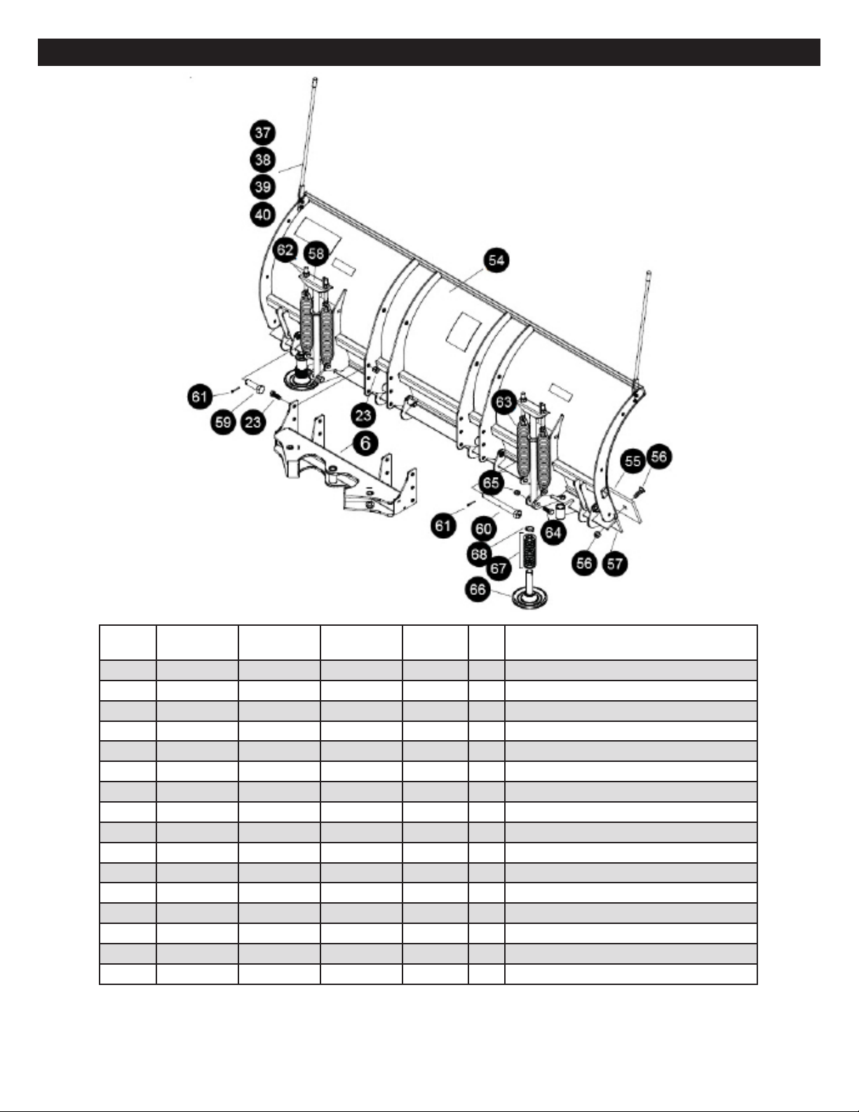
Item Part No.
7’ 6”
Part No.
8’
Part No.
8’ 6”
Part No.
9’ Qty Description
84350 84351 84352 84353 1 Moldboard Assembly
54 84360 84361 84362 84363 1 • Moldboard Weld
55 84127 84128 84129 84130 1 • Cutting Edge
56 08223 08223 08223 08223 1 • Bolt C 5/8-11 x 2” Gr.5 & Locknut (Kit of 10)
57 84370 84371 84372 84373 1 • Trip Edge Weldment
58 84285 84285 84285 84285 2 • T-Bar Weldment
59 22331 22331 22331 22331 2 • Pivot Pin 1 x 3-5/16”
60 22375 22375 22375 22375 2 • Pivot Pin 1 x 8-3/4”w/grease tting
61 20406 20406 20406 20406 4 • Cotter Pin 3/16 x 1-1/ 2”
62 09124 09124 09124 09124 4 • Eye Bolt w/Locknut & Cap
63 07017 07017 07017 07017 4 • Trip Spring
64 20144 20144 20144 20144 2 • Bolt H 5/8 - 11 x 2-3/4” Gr. 5
65 20318 20318 20318 20318 2 • Locknut Esna 5/8-11
66 13150 13150 13150 13150 2 • Wear Shoe Assy
67 20363 20363 20363 20363 24 • Runner Washer
68 22083 22083 22083 22083 2 • Lynch Pin
(4)
Moldboard Parts List
Parts indented are included in the assembly under which they are indented.
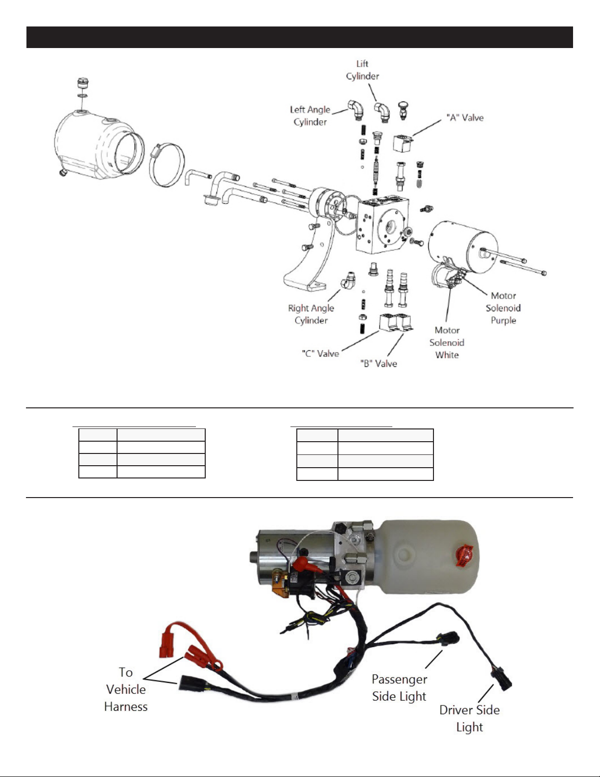
(5)
Hydraulic Solenoid Color
Raise Motor Solenoid +“B” Solenoid
Lower “A” Solenoid
Left Angle Motor Solenoid
Right Angle Motor Solenoid + “C” Solenoid
Motor White
A Black
B Red
C Green
Coil Wire Color Code:
Note:Note: Ground wire for each coil is
Black with a White Stripe
E73 Hydraulics

(6)
Wiring Harnesses & Controller
Vehicle Side HarnessVehicle Side Harness
1) Route the 12 pin connector into vehicle’s cab and plug into controller.
2) Route the 16 pin connector to the front of the vehicle and plug into the plow side harness.
3) Route the 4 pin connector to rear of vehicle and plug into vehicle’s trailer harness using the trailer adapter harness.
Use cable ties to ensure the harness is secured to the vehicle’s frame.
4) The BLUE wire will connect to the vehicle’s keyed accessory circuit. This is to ensure the plow turns on and o with the vehicle’s igni-
tion.
The following step is for 2015 & later GM vehicles with an alternator relay...The following step is for 2015 & later GM vehicles with an alternator relay...
5) The WHITE wire will connect to 2015 & Later GM vehicles with alternator relay. See Meyer Products Service Bulletin SB252.
6) The PURPLE wire will connect to the black /violet wire of 2015 and later models of RAM 2500, 3500, 4500, and 5500 models. See
mount instructions for further detail.
The following two steps are optional and may be enforced by local law which requires your vehicle lights to be o while your plowThe following two steps are optional and may be enforced by local law which requires your vehicle lights to be o while your plow
lights are on and vice versa...lights are on and vice versa...
6) Connect the RED to the HIGH beam function.
7) Connect the WHITE to the LOW beam function.
Power HarnessPower Harness
1) Route through the vehicle’s grille.
2) Connect the terminals to the vehicle’s battery. Red to Positive and Black to Negative.
Trailer Adapter Harness
(7)
Plow Assembly & Adjustments
Nite Saber LED LightsNite Saber LED Lights
See seperate Nite Saber LED instructions for further information.
Mount the lights as shown below.
Connect both male ends from the snow plow light to the female ends on the
Plow Side Harness. Ensure all wiring harnesses are secured against the lift
frame.
Check snow plow lights and blinkers to ensure proper operation. If operating
in reverse (i.e. driver side blinking instead of passenger side), reverse the har-
ness connections.
Note: All electrical connections should have both ends coated with a dielectric
grease (Meyer Part # 15632) prior to nal installation. This will ensure a good
connection and help in preventing corrosion.
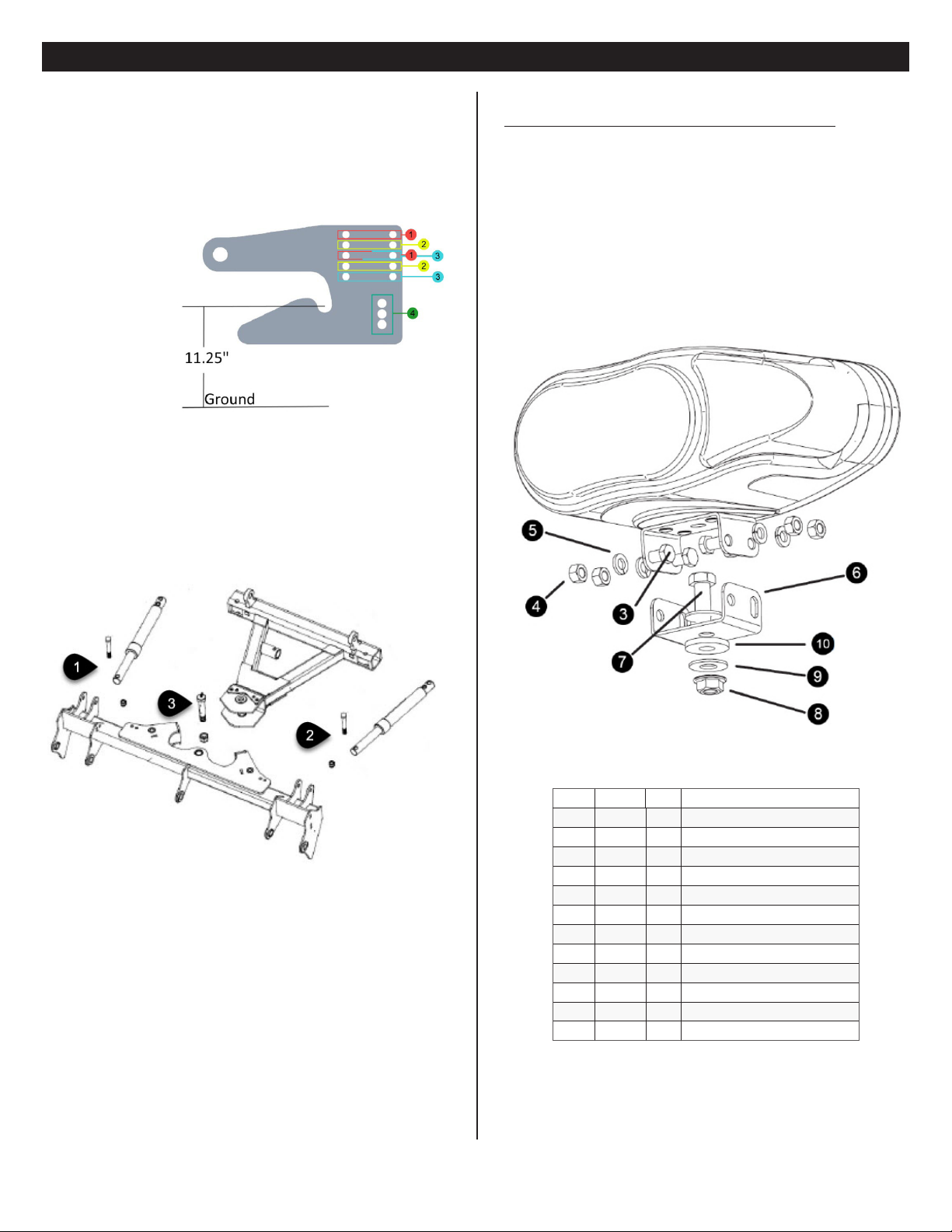
Nite Saber LED Parts List
Item Part QTY Description
- 23067 1 Nite Saber LED Kit
- 23066 1 Passenger Side LED
- 23065 1 Driver Side LED
- 08126 1 Hardware Bag
3 ----- 8 • Hex Bolt 3/8” x 3/4”, SS
4 ----- 8 • Hex Nut 3/8”, SS
5 ----- 8 • Lock Washer 3/8”, SS
6 ----- 2 • Metal Bracket, Bottom
7 ----- 2 • Bolt 1/2”- 13 x 1 1/12”, SS
8 ----- 2 • Hex Lock Nut 1/2”- 13, SS
9 ----- 4 • Flat Washer 1/2”, SS
10 ----- 2 • Neoprene Grommet 1/2”
Adjustable ClevisAdjustable Clevis
The 14700 adjustable clevisThe 14700 adjustable clevis is now standard with all Standard Operating Sys-
tem black iron packages. The 14700 Adjustable Clevis cannot be used with any
EZ+ Operating System plow model.
The 14700 Clevis oers 3 levels of adjustability for a height dierence of +/- 1.5
inches. To use the adjustability feature, mounting the clevis using two sets of
applicable holes. Use one of the bottom 3 holes to secure to the clevis to the
mount.
Level 1 = Rows 1 and 3
Level 2 = Rows 2 and 4
Level 3 = Rows 3 and 5
The clevis requires a height of 11.25”o the ground in order for the plow to sit
level.
Pivot BarPivot Bar
The Pivot Bar will need to be bolted to the A-Frame and Angling Cylinders. Cut
any ties that are securing the cylinders to the crate prior to removing black
iron from the crate. The Angling Cylinders will already be connected to the Lift
Frame. Hardware to attach the Pivot Bar to the Angling Cylinders and A-Frame
can be found in the Accessory Box.

(8)
Plow Assembly & Adjustments
Lift ChainsLift Chains
Attach the Lift Chain to the Lift Arm through the two hooks on the lift
arm. Adjust the lift chain at the lift arm so that there are 2-3 links of slack.
This ensures that the plow blade will lift fully and be able to follow the ground
contour while plowing.
Trip Spring AdjustmentTrip Spring Adjustment
Attach Eye Bolts to Moldboard and Trip Springs to Pivot Bar, making certain
locknuts are positioned as shown below.
Make certain each Eye Bolt is in a vertical position as shown below so that the
Eye Bolt and Trip Spring hinge properly when the Moldboard trips.
Note: Proper tension is attained when the Trip Spring coils just begin to
seperate and then tightening top locknut four additional turns. Tighten
bottom locknut to secure Eye Boilt in positiion.
Install Eye Bolt Caps over exposed threads.
Plow MarkersPlow Markers
Attach Plow Markers to moldboard using 5/16-18 x 1”Bolt, 5/16” Flatwasher,
and 5/16-18 Locknut.
Drop Speed AdjustmentDrop Speed Adjustment
E73 Drop Speed Adjustment: Loosen jam nut and turn knob clockwise to slow
the drop of the plow and counter clockwise to speed the drop of the plow.
Tighten jam nut.
Drop Speed Adjustment
Hydraulic Fluid LevelHydraulic Fluid Level
Top o the unit to the ll line on the reservoir with Meyer M-1 Hydraulic Fluid.
NOTE: Proper uid level is to the ll line on the reservoir for the E73. It must be
checked with the lift cylinder fully retracted.
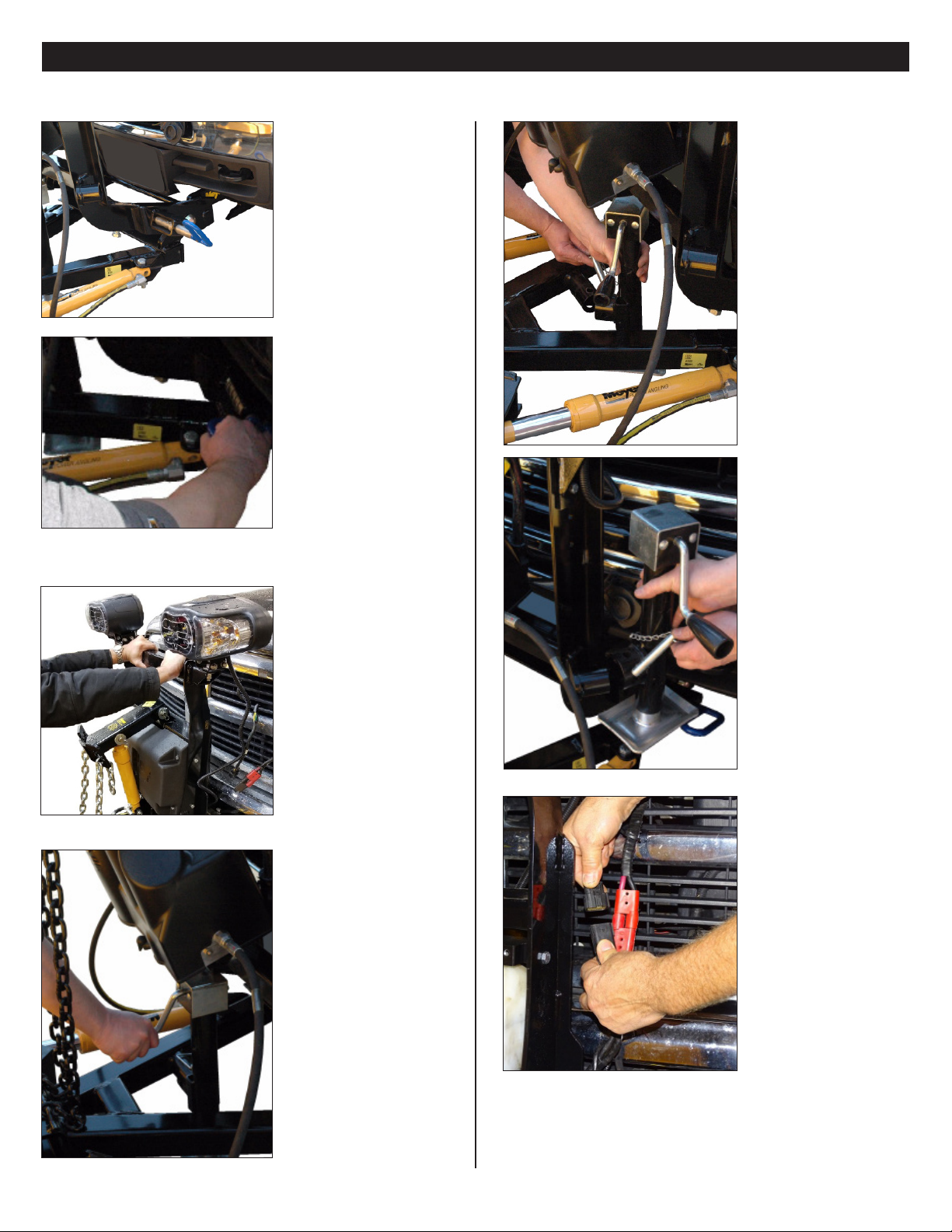
A.A. Pull vehicle into plow
assembly and push plow
assembly forward an
inch or two.
F.F. Attach crankstand to
lift frame.
E.E. Remove crankstand
from a-frame.
D.D. Adjust crankstand
until it is no longer in
contact with the ground.
C.C. Push back on lift
frame until both pins
spring through mount on
vehicle.
B.B. Twist handles on both
sides to engage spring
loaded pins.
G.G. Remove weather
cover on both ends and
connect both electrical
plugs.
(9)
Mounting Plow
NOTE:NOTE: Pictures may vary based on model

B.B. Push lift arm down until there is slack in the chain.
C.C. Remove crankstand
from lift frame.
D.D. Attach crankstand to
a-frame
F.F. While slightly pushing the lift frame towards vehicle pull
handles on either side to disengage pins then twist until the
leg locks the pin in the open position.
G.G. Disconnect both
electrical plugs and in-
stall weather cover on
both ends.
H.H. Back vehicle away
from plow assembly.
(10)
Dismounting Plow
A.A. Press down button
until oat light turns blue.
E.E. Adjust crankstand until
the crankstand comes in
contact with the ground
and then turn 1 to 2
revolutions.
Vehicle Make: Vehicle Model:
Vehicle Year: Vehicle VIN#:
Vehicle FGAWR: Installing Company:
Hydraulic Serial Number: Moldboard Serial Number:
PRE-DELIVERY INSPECTION
All bolts torqued to specication
Suspension interference
Clevis height in inches
Trip springs adjusted
Lift Chain Adjusted
Check for hydraulic uid leaks
Hydraulic uid Level
Dielectric grease applied to ALL electrical connection
All wires secured
Plow Stops Adjusted (plow cannot bump hyd. unit)
Controller Operation
Plow Operation Up
Plow Operation Left
Plow Operation Right
Plow Operation Down
Plow Light Blinker Left & Right Operation
Plow Light Low & High Beam Operation
Plow Lights Adjusted
Plow Mount/Dismount reviewed with Customer
Plow Operation reviewed with Customer
Warranty/Registration/Owners Manual
Reviewed with Customer
(11)
11-1/4"
Clevis height
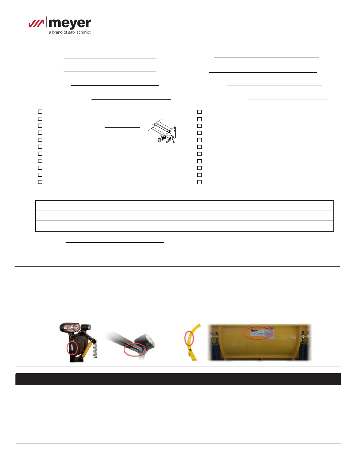
Serial Number Decal Locations
Moldboard serial tags are attached to the back of the moldboard, the outter rib of the moldboard, and on the black iron near the
hydraulic unit.
Note: SV3 Plows use the same serial number for both hydraulic and moldboard.
Registration ID ________________
You must register your plow online to be eligible for the 5 year warranty. Please visit...
www.meyerproducts.com/product-registration
Please note your registration ID for future reference.
Registration
Notes:
Inspected By:
Customer Signature:
W.O.#: Date:
Table of contents


