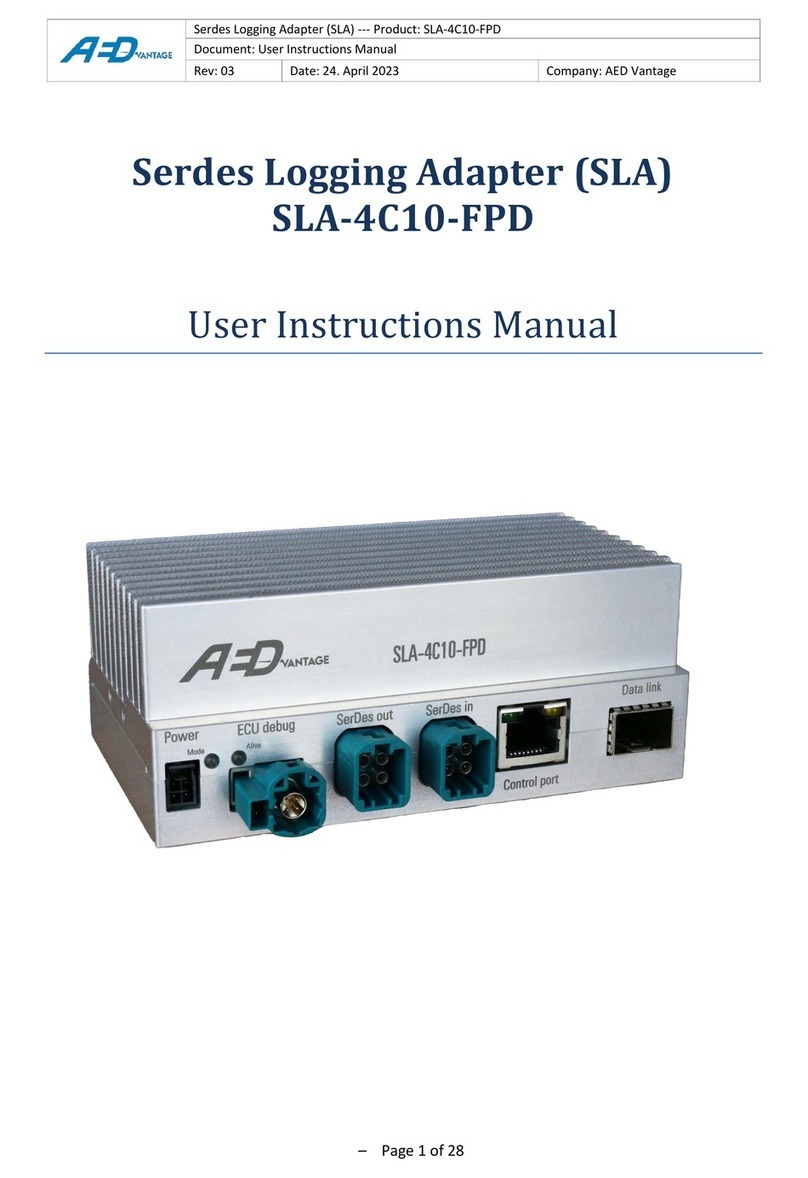
AED VANTAGE SLA-1C10-FPD4 Operator's manual

Serdes Logging Adapter (SLA) --- Product: SLA-1C10-FPD4
Document: User Instructions Manual
Rev: 1
Date: 08. May 2023
Company: AED Vantage
Public –Page 1 of 28
Serdes Logging Adapter (SLA)
SLA-1C10-FPD4
User Instructions Manual

Serdes Logging Adapter (SLA) --- Product: SLA-1C10-FPD4
Document: User Instructions Manual
Rev: 1
Date: 08. May 2023
Company: AED Vantage
Public –Page 2 of 28
Classification: Public
Revision: 1
Date: 08. May 2023
REVISION HISTORY
REV
DATE
AUTHOR
DESCRIPTION
01
08.05.2023
Danny Meyer
Document creation,
new product variants added,
new Wiki page link, updated device weight,

Serdes Logging Adapter (SLA) --- Product: SLA-1C10-FPD4
Document: User Instructions Manual
Rev: 1
Date: 08. May 2023
Company: AED Vantage
Public –Page 3 of 28
Table of contents
1 Introduction.............................................................................................................................................6
1.1 General Information........................................................................................................................6
1.2 Further products..............................................................................................................................6
1.3 Available manuals............................................................................................................................6
1.4 Pictograms.......................................................................................................................................6
2 Safety Notes ............................................................................................................................................7
2.1 General safety instructions .............................................................................................................7
2.2 Product liability................................................................................................................................9
2.3 Terms of use....................................................................................................................................9
2.4 Warranty..........................................................................................................................................9
3 Intended use and integration into system........................................................................................... 10
3.1 Important notices......................................................................................................................... 10
3.2 Additional notices to electrical Grounding issues........................................................................ 11
4 Installation and Operation ................................................................................................................... 12
4.1 Identification ................................................................................................................................ 12
4.2 Connections and controls............................................................................................................. 13
5 Installation location.............................................................................................................................. 17
5.1 Grounding..................................................................................................................................... 17
5.2 ESD................................................................................................................................................ 17
5.3 General environmental conditions............................................................................................... 17
6 Quick Start Guide ................................................................................................................................. 18
6.1 Power up the device..................................................................................................................... 18
6.2 Connect with SLA via control port interface ................................................................................ 18
6.3 Get access to the web interface................................................................................................... 19
7 Example use case.................................................................................................................................. 20
7.1 Logging mode ............................................................................................................................... 20
7.2 Replay mode................................................................................................................................. 21
8 Recovery mode..................................................................................................................................... 22
9 Technical specification ......................................................................................................................... 24
10 Storage, transport and disposal ........................................................................................................... 25
10.1 Storage ......................................................................................................................................... 25
10.2 Transport...................................................................................................................................... 25
10.3 Disposal ........................................................................................................................................ 25
11 Maintenance and Service..................................................................................................................... 26
11.1 Safety measures ........................................................................................................................... 26
11.2 Cleaning........................................................................................................................................ 26
11.3 Repair ........................................................................................................................................... 27
11.4 Service .......................................................................................................................................... 27

Serdes Logging Adapter (SLA) --- Product: SLA-1C10-FPD4
Document: User Instructions Manual
Rev: 1
Date: 08. May 2023
Company: AED Vantage
Public –Page 4 of 28
Table of figures
Figure 4-1 Nameplate of the SLA...................................................................................................................12
Figure 4-2 Front side ports of the SLA...........................................................................................................13
Figure 4-3 Pinning of Power and Wake connector........................................................................................14
Figure 4-4 Summary of LED status ................................................................................................................14
Figure 4-5 Pinning of ECU debug connector .................................................................................................15
Figure 4-6 Pinning of SerDes out connector..................................................................................................15
Figure 4-7 Pinning of SerDes in connector....................................................................................................16
Figure 6-1 Web interface shows configuration editor ..................................................................................19
Figure 7-1 Application example in SLA logging mode ...................................................................................20
Figure 7-2 Application example in SLA replay mode in HiL environment.....................................................21
Figure 8-1 Stages and LED states of recovery mechanism............................................................................23
Figure 9-1 Technical Data..............................................................................................................................24

Serdes Logging Adapter (SLA) --- Product: SLA-1C10-FPD4
Document: User Instructions Manual
Rev: 1
Date: 08. May 2023
Company: AED Vantage
Public –Page 5 of 28
Terms and Acronyms
Term/Acronym
Definition
AB
Adapter-Board
CPU
Central Processing Unit
CSI
Camera Serial Interface
DLM
Data Logger Module
ECU
Electronic Control Unit
EEA
European Economic Area
ESD
Electrostatic Discharge
FPD-Link
Texas Instruments Flat Panel Display Link
FPGA
Field-Programmable Gate Array
GMSL
Maxim Gigabit Multimedia Serial Link
HIL
Hardware In The Loop
IP v4
Internet Protocol version 4
LED
Light-Emitting Diode
MIPI
Mobile Industry Processor Interface
MIPI CSI-2
MIPI Camera Serial Interface 2
MPO/MTP
Multi-fiber Termination Push-on
MTA
Mess-Technik-Adapter (Measurement Equipment Adapter)
PoC
Power over Coax
PTP
Precision Time Protocol (IEEE 802.1AS)
QSFP+
Quad Small Form-factor Pluggable (40Gb/s capable)
RX
Receiver
SerDes
De-/serializer pair of blocks: hardware for serial/parallel intercommunication
SFP+
Small Form-factor Pluggable (10Gb/s capable)
SLA
SerDes Logging Adapter
STP
Shielded Twisted Pair
TI
Texas Instruments
TX
Transmitter
WEEE
Waste of Electrical and Electronic Equipment

Serdes Logging Adapter (SLA) --- Product: SLA-1C10-FPD4
Document: User Instructions Manual
Rev: 1
Date: 08. May 2023
Company: AED Vantage
Public –Page 6 of 28
1Introduction
1.1 General Information
The SerDes Logging Adapter (SLA) is part of a measurement equipment infrastructure for test vehicles
with MIPI CSI-2 based sensor ECU systems. This manual contains important advice, notes, and
information about the SLA. Read this manual carefully. It helps avoiding accidents, reduces repair costs
and extends the operating time of the SLA.
1.2 Further products
Product
Description
SLA-1C-GMSL
1 Channel Maxim GMSL2 up to 6 Gb/s, Coax
SLA-1C10-FPD4
1 Channel Texas Instruments FPD-link-IV up to 6 Gb/s, Coax
SLA-1S-GMSL
1 Channel Maxim GMSL2 up to 6 Gb/s, Shield Twisted Pair (STP)
SLA-4C-GMSL
4 Channel Maxim GMSL2 up to 6 Gb/s, Coax
SLA-4C20-GMSL3
4 Channel Maxim GMSL3 up to 12 Gb/s, Coax
SLA-4C10-FPD
4 Channel Texas Instruments FPD-link-III up to 4.16 Gb/s, Coax
AB-ADCAM-MID
Debug-Board for ADCAM-MID application
SLA-DCDC-30W
Galvanic isolated power source
Offline Decompression
SW to decompress frame or line-based compressed data logged by the SLA
with GPU or CPU. Includes basic visualisation.
HiL Framework
SW to reinject PCAP or MDF files from Host-PC through SLA to the ECU.
1.3 Available manuals
•User Instructions Manual
•Technical datasheet
•User Reference Manual
1.4 Pictograms
The following pictograms are used in the following to highlight important information related to the safe
operation and handling of the SLA:
Warning
This pictogram combined with the word “Warning”warns of a potentially imminent
danger to the health and lives of people.
Ignoring this warning could cause serious personal injury, including death in the worst
case.
Caution
This pictogram combined with the word “Caution”warns of a potentially dangerous
situation or an unsafe procedure.
Ignoring this warning could result in injury of people or property and environmental
damage.

Serdes Logging Adapter (SLA) --- Product: SLA-1C10-FPD4
Document: User Instructions Manual
Rev: 1
Date: 08. May 2023
Company: AED Vantage
Public –Page 7 of 28
2Safety Notes
2.1 General safety instructions
Damage due to overvoltage
Application of overvoltage may cause destruction of the device.
Caution
▪Only apply the voltage to the device as specified in the data sheet
Damage or malfunction due to electrostatic discharge
Electrostatic discharge may cause damage the device.
Caution
▪Operate the device only in ESD-compliant environment
▪Make sure to ground yourself before touching the device
▪Do not touch connectors
▪Observe section 5
Damage or malfunction due to unauthorized opening
Unauthorized opening of the device may cause abnormal behavior or destruction of the device.
Caution
▪Do not open the housing in any case
▪Contact the manufacturer if repair is required
Safety and functional defects due to incorrect accessories and spare parts
Accessories or spare parts that are not recommended by AED Vantage GmbH may have adverse effects
on the safety and functionality of the device.
Caution
▪Do only use and connect original accessories and spare parts that are
recommended by AED Vantage GmbH
Damage or malfunction due to incorrect connection
Incorrect connection of cables may cause abnormal behavior or destruction of the device.
Caution
▪Do only connect cables according to the specification
▪Do only apply the signals and voltages to inputs and outputs as specified in
section 4 and data sheet
Damage or malfunction due to short circuit
Wrong connected or defect cables may cause a short circuit which may cause abnormal behavior or
destruction of the device.
Caution
▪Make sure that the cable insulation and plugs of the cables and the device are
intact and the cables are correctly mounted
▪Observe section 4
Damage or malfunction due to overheating
Overheating may cause abnormal behavior or destruction of the device.
Caution
▪Operate the device only within the specified temperature range and ensure
proper ventilation
▪Do not cover the device during operation
▪Do not operate the device close to heat sources

Serdes Logging Adapter (SLA) --- Product: SLA-1C10-FPD4
Document: User Instructions Manual
Rev: 1
Date: 08. May 2023
Company: AED Vantage
Public –Page 8 of 28
▪Observe section 5
Hot Surfaces
The surfaces of the device may have elevated temperatures during operation
Warning
▪Avoid touching the housing during operation
Damage or malfunction due to shocks
Excessive mechanical shocks and vibration may cause abnormal behavior or destruction of the device.
Caution
▪Do not expose the device to excessive mechanical shocks and vibration during
transport, operation and storage
Damage or malfunction due to penetration of dust, moisture or liquids
Dust, moisture or liquids inside the device may cause abnormal behavior or destruction of the device.
Caution
▪Transport, store and operate the device in a clean environment
▪Only clean the device in de-energized status
▪Do not use wet wipes near plugs or openings in the housing
▪Observe section 5
Damage or malfunction due to pollution
Any contamination may affect the functionality of the device
Caution
▪Transport, store and operate the device in a clean environment
Overcurrent when using Power-over-Coax (PoC)
Malfunction or damage of device possible
Caution
▪Limit the current for PoC to the max. specified current of the SLA (e.g. by current
limitation in the ECU)
Grounding issues / Ground loops
Malfunction or damage of device possible
Caution
▪Use galvanically isolated power supply for the SLA to avoid any grounding issues
▪Observe section 3.2
LASER class 1
SFP+ modules inside the Data Link connector (see section 4.2) contain a LASER class 1.
Warning
▪Do not view directly into the module with optical instruments, as this may be
harmful for the eyes

Serdes Logging Adapter (SLA) --- Product: SLA-1C10-FPD4
Document: User Instructions Manual
Rev: 1
Date: 08. May 2023
Company: AED Vantage
Public –Page 9 of 28
2.2 Product liability
Manufacturer liability for damage caused by using the device is excluded.
If the device is not strictly used in the intended way then the liability is transferred to the user.
The following cases are examples for not intended usage:
•The device is used in series production cars.
•The device is not used according to the user manual or according to the described scope.
•Modifications are done to the device without permission of AED Vantage GmbH.
•Installation instructions of the device are not fulfilled.
2.3 Terms of use
The device is designed to be used for engineering purpose only. Special care has to be taken during
operation of the device. Installation in series production cars is not scope of this product.
The usage of the SLA must apply to all of the described installation instructions (User Instructions
Manual).
All safety requirements have to be fulfilled by the overall system in the car excluding the device. Users of
cars equipped with the device have to be instructed about possible risks (for example communication
interruption) and proper handling of the SLA.
2.4 Warranty
Warranty period is limited to 12 months as this device is likely to be used under rough conditions.
Excluded are damages due to improper installation, improper handling, modification of the product or
usage of the product not according to the described scope or not according to the manual.
Manufacturers liability for damage caused by using the device is excluded.

Serdes Logging Adapter (SLA) --- Product: SLA-1C10-FPD4
Document: User Instructions Manual
Rev: 1
Date: 08. May 2023
Company: AED Vantage
Public –Page 10 of 28
3Intended use and integration into system
The SLA and Adapter Boards can be installed in test-vehicles for recording of the sensor and debug port
data. In this use case the sensor data will be forwarded to the ECU and simultaneously sent to the DLM
for logging purposes. Debug data from ECU interfaces will be handled by the Adapter Board and recorded
through the SLA.
In laboratory environment, typically the reinjection mode is used (e.g. in HIL environment). The formerly
recorded data will be sent to the SLA from a server and sent to the ECU. Debug data from ECU interfaces
will be handled by the Adapter Board and can be recorded through the SLA or reinjected towards the
ECU.
3.1 Important notices
•Use the SLA only as a measurement probe for electrical high speed busses, especially SerDes links
•Users must be qualified in electronic or electrical engineering.
•Users must be qualified for using measurement instrumentation.
•The SLA is for industrial environments only. No use in domestic environments.
•The SLA is for test vehicles only (no use in series vehicles).
•No liability for any failures caused by the product to the functionality of the ECU and other
vehicle functionality. Risk analysis needs to be done by the user for operation in vehicles on
public roads.
•In case of variant SLA-1C-GMSL, SLA-4C-GMSL, SLA-4C-FPD, SLA-4C10-FPD, SLA-1C10-FPD4, SLA-
4C20-GMSL3:
PoC over-current protection needs to be taken care of in ECU.
•Do not use in a safety related system or signal path.
•Do not use in hazardous areas.
•Do not use in wet locations or in areas where moisture or condensation can be expected.
•Do not use the device in outdoor locations.
•Use the SLA according to its technical specifications.
•Use a regulated power supply or car battery and observe the technical specifications of the SLA.
AED Vantage GmbH recommends the use of isolating DC/DC converters between power input of
the SLA and power supply (e.g. AED DC/DC converter: SLA-DCDC-30W).
•Do not open, modify or repair the SLA. Otherwise operational safety cannot be guaranteed.
•Repairs are only carried out by AED Vantage GmbH.
•Avoid ground-loops through the device in a measurement system.
•The SLA must remain switched off for at least 10 seconds before it can be switched on again.

Serdes Logging Adapter (SLA) --- Product: SLA-1C10-FPD4
Document: User Instructions Manual
Rev: 1
Date: 08. May 2023
Company: AED Vantage
Public –Page 11 of 28
3.2 Additional notices to electrical Grounding issues
•The coax cables between cameras, SLAs and ECUs have a common ground connection by the
nature of the application’s sensor to ECU connection. For this reason, the SLAs power supply
must be galvanically isolated from the ECUs power supply. Otherwise physical damage to the ECU
and/or SLA devices is likely to be observed as well as a degradation of the sensor signal quality.
•AED recommends using the SLA-DCDC-30W isolated DC/DC converter for the power supply of
every individual SLA to avoid misfunction or damage of SLAs, sensors, or ECUs because of ground
loops.
•It is the responsibility of the customer to avoid ground loops. AED will not take liability for any
damages or malfunction caused by grounding issues.

Serdes Logging Adapter (SLA) --- Product: SLA-1C10-FPD4
Document: User Instructions Manual
Rev: 1
Date: 08. May 2023
Company: AED Vantage
Public –Page 12 of 28
4Installation and Operation
4.1 Identification
A laser engraved nameplate on the bottom of the SLA contains the following information:
Figure 4-1 Nameplate of the SLA
•P/N: Device type and version
•S/N: Serial number
•Rev: Hardware Revision
•(DD/MM/YY): Date of production
•Input: Max. current consumption @ nominal supply voltage
•Conformity of standards for product sold within the EEA
•Warning of hot surface
•Read operators manual
•Electronic device according to WEEE
By contacting our support always provide device type, revision and serial number.
The interface parameters are configurable and not part of the nameplate. For detailed information about
the interface configuration see section 6.

Serdes Logging Adapter (SLA) --- Product: SLA-1C10-FPD4
Document: User Instructions Manual
Rev: 1
Date: 08. May 2023
Company: AED Vantage
Public –Page 13 of 28
4.2 Connections and controls
This section provides an overview of the physical interfaces of the SLA. The following pictures provide an
overview of the front side interfaces and their positions.
Front Side
A
Power:
•Power Supply voltage 12 V nom.
•2 Wake-up inputs
•Connector type Molex Nano-Fit 4 pin
F
SerDes in:
•Connector type Coax
TE Mate-AX 1 pos.
•Connection of sensor output
•PoC available
B
Left status LED: Mode
G
Control port:
•Interface type 1000Base-T
•Connector Type TE RJ45
C
Right status LED: Alive
H
Left status LED of control port: Activity
D
ECU debug port:
•Connector type Rosenberger HSD+2
•Data Connection to Extension Board
•Power supply of Extension Board
optionally supplied from SLA
•Cable length up to 2 m
•Output power available up to 8 W
I
Right status LED of control port: Link
E
SerDes out:
•Connector type Coax
TE Mate-AX 1 pos.
•Connection of ECU
•PoC available
J
Data link:
•Connector TE SFP+ slot
•Connection to logger device
Figure 4-2 Front side ports of the SLA

Serdes Logging Adapter (SLA) --- Product: SLA-1C10-FPD4
Document: User Instructions Manual
Rev: 1
Date: 08. May 2023
Company: AED Vantage
Public –Page 14 of 28
A. Power and wake connector
By default, the SLA must be supplied with 12 V DC voltage. According to the technical datasheet it
can also operate with power supplies between 8 V and 16 V. You can download this document at
the AED wiki see section 11.4. The external wake inputs allow waking up the SLA from sleep. The
wake signal must shift from 0 V to +12 V and must be activated in internally configuration.
Power and Wake connector
Molex 105314-1104
Pin 2
GND
(VBAT-)
Pin 1
+12V
(VBAT+)
Pin 3
WAKE1
Pin 4
WAKE2
Figure 4-3 Pinning of Power and Wake connector
B. Left status LED
The left status LED indicates the mode of the SLA.
Green (continuous): Logging
Red (continuous): Replay
C. Right status LED
The right status LED indicates the alive status of the SLA.
Green (flashing): Alive
Red (continuous): Fault detected
LED left
LED right
Status
Off
Off
No Power or Standby-Mode
Constant green
Flashing green
Logging-Mode
Constant red
Flashing green
Replay-Mode
Constant red
Constant red
Device is booting
Others
Others
Error occurs or SLA is running the
recovery process, see section 8.
Figure 4-4 Summary of LED status

Serdes Logging Adapter (SLA) --- Product: SLA-1C10-FPD4
Document: User Instructions Manual
Rev: 1
Date: 08. May 2023
Company: AED Vantage
Public –Page 15 of 28
D. ECU debug port
The ECU debug connector is AED Vantage´s designation to the Aurora-based proprietary SERDES
bidirectional communication protocol established between two Xilinx FPGAs: the one located at
the SLA and the second present on a customer-specific Adapter Board directly attached to the
ECU.
The main objective of the ECU debug port is aggregating and sending some interfaces of interest
from the Adapter Board to the SLA, most of them to be timestamped and logged (next to the
original SLA’s MIPI data and sideband interfaces). Optionally an Ethernet interface form the
Adapter Board may also be forwarded to the SLA’s Control.
The connector used is hybrid: it has two SERDES twisted pairs for TX/RX and a separate optional
third pair (12 V output) able to forward the SLA’s main power input (+12V nominal) to the Debug
Module. Beware, Pin 5 and Pin 6 operate as voltage output. Do not connect any other voltage
supply to these pins.
Therefore, do not connect two SLAs via ECU-link with each other. This is not a use-case. The
output voltage of 12 V on both sides of the SLA, will defect the device and maybe other devices
connected through.
ECU debug connector
Rosenberger HSD+2
Pin 5
+12V
out
Pin 1
TX+
Pin 4
RX-
Pin 6
GND
Pin 2
RX+
Pin 3
TX-
Figure 4-5 Pinning of ECU debug connector
E. SerDes out:
SerDes interfaces are handling the MIPI CSI-2 signals coming from the cameras or sensors to the
ECU. It enables forward channel data rate up to 6 Gb/s and back channel data rate 187.5 Mb/s.
SerDes out is serial Coax connector and is connected to an ECU. A PoC mechanism to supply 12 V
over the coaxial cable to the sensors is supported.
SerDes Out pin mapping
1 channel Coax connector
Pin 1
Shield
Pin 2
Out
Figure 4-6 Pinning of SerDes out connector

Serdes Logging Adapter (SLA) --- Product: SLA-1C10-FPD4
Document: User Instructions Manual
Rev: 1
Date: 08. May 2023
Company: AED Vantage
Public –Page 16 of 28
F. SerDes in:
SerDes interfaces are handling the MIPI CSI-2 signals coming from the cameras or sensors to the
ECU. It enables forward channel data rate up to 6 Gb/s and back channel data rate 187.5 Mb/s.
SerDes in is a Coax connector and is connected to the sensor. A Power-over-Coax (PoC)
mechanism to supply 12 V over the coaxial cable to the sensors is supported.
SerDes In pin mapping
1 channel Coax connector
Pin 1
Shield
Pin 2
In
Figure 4-7 Pinning of SerDes in connector
G. Control port:
Communication between the SLA’s CPU and an external host is accomplished via 1000BASE-T
interface. This interface has many potential use-cases, like providing access to a web-based page
for monitoring and configuration of the whole SLA system or a PTP-based time synchronization
with an external clock master (IEEE 802.1AS). The Control Port sometimes is also referred to as
Management Port. The RJ45 provides two integrated status LEDs.
H. Left status LED of control port:
The yellow LED indicates the link activity of the control port.
I. Right status LED of control port:
The green LED signalling that link is established.
J. Data Link:
10G Ethernet interface with SFP+ slot for connectivity between SLA and a Data Logger Module
(DLM) with the purpose of externally storing the MIPI CSI-2 data and sideband interfaces flowing
between sensors and ECU. Further use case is to retransmit data to the ECU which was previously
stored or synthesized –in the case of HIL mode.
The selection of qualified SFP+ modules and cables is still subject of change. For a list of verified
and supported SFP+ modules and cables please contact AED Vantage GmbH.
LASER class 1
SFP+ modules may contain a laser:
•All optical SFP+ modules supplied by AED contain a LASER class 1,
IEC60825-1 Laser Safety compliant.

Serdes Logging Adapter (SLA) --- Product: SLA-1C10-FPD4
Document: User Instructions Manual
Rev: 1
Date: 08. May 2023
Company: AED Vantage
Public –Page 17 of 28
5Installation location
Always prepare the protection of the SLA against external damage. As proper location for installation
serves preferably a firm and stable base.
5.1 Grounding
For installation in test vehicles, it is required to provide an electrical connection of the enclosure of the
SLA with the chassis of the vehicle by e.g. fixing bracket or copper tape.
•Impedance (Z): < 50mOhm
•Resistance (R): < 10mOhm
5.2 ESD
Operate with the device in an ESD-compliant environment.
5.3 General environmental conditions
The following general environmental conditions shall be considered when using the SLA:
•Indoor use only except in automotive test vehicles
•Altitude up to 3000 m
•Operating temperature -30 °C … +70 °C
•Maximum relative humidity 95 % non-condensing
•No use in wet locations or in areas where moisture or condensation can be expected
•Supply voltage fluctuations between +8 VDC and +16 VDC
•Transient over-voltages up to the levels of overvoltage category I (CAT I)
•Pollution degree 2: Only non-conductive pollution occurs except that occasionally a
temporary conductivity caused by condensation is to be expected
It is the responsibility of the user to provide sufficient cooling keeping the SLA within its specified
temperature limits in all cases. Further details are provided in the technical data sheet. You can download
this document from the AED wiki see section 11.4.

Serdes Logging Adapter (SLA) --- Product: SLA-1C10-FPD4
Document: User Instructions Manual
Rev: 1
Date: 08. May 2023
Company: AED Vantage
Public –Page 18 of 28
6Quick Start Guide
6.1 Power up the device
Before powering the device, make sure to read and understand the safety notes in section 2. Connect the
SLA to a power supply which provides 12 V DC nominal. AED recommends using a galvanically isolated
power supply (e.g. power supply in combination with AED DC/DC converter: SLA-DCDC-30W). Please note
the port pinning assignments in section 4.2 and read the important notices in section 3. The SLA will boot
automatically. After booting, the SLA will start up in logging-mode by default.
Please note that the device must remain switched off for at least 10 seconds before it can be switched on
again.
6.2 Connect with SLA via control port interface
Connect the SLA via ethernet cable from your PC to the SLA control port. The control port interface can
be accessed through one of two IP v4 addresses. Beware, the user IP address of the 1G Port is
configurable and persistent. The secondary static IP v4 address is pre-configured by factory which cannot
be changed. This provides a guaranteed way of accessing the SLA device for configuration and
management as a fallback.
•IPv4 user (default): 10.104.3.192
•IPv4 secondary (fixed): 192.178.1.100

Serdes Logging Adapter (SLA) --- Product: SLA-1C10-FPD4
Document: User Instructions Manual
Rev: 1
Date: 08. May 2023
Company: AED Vantage
Public –Page 19 of 28
6.3 Get access to the web interface
The web interface is the preferred way to configure the SLA for an application. This section explains how
the get access to the Web Interface of the SLA. Enter the IP address of the SLA in your favorite web
browser and a web interface like this shows up:
In this interface it is possible, amongst other things, to configure parameters, read out status-registers of
the SLA, change operating mode or execute an update. For further details see the User Reference
Manual. You can download this document at the AED wiki see section 11.4.
Figure 6-1 Web interface shows configuration editor

Serdes Logging Adapter (SLA) --- Product: SLA-1C10-FPD4
Document: User Instructions Manual
Rev: 1
Date: 08. May 2023
Company: AED Vantage
Public –Page 20 of 28
7Example use case
The SLA can be used in two different ways. In logging mode, for forwarding the sensor data to the ECU, or
in replay mode for laboratory use in HiL test benches. In both ways prepare not sending data during the
start-up time of the SLA. There are two examples of typical applications below:
7.1 Logging mode
Figure 7-1 Application example in SLA logging mode
Be careful not to swap the SerDes ports. The sensor is connected to SerDes in and the ECU is connected
to SerDes out. Wrong connection can damage the device.
Table of contents
Other AED VANTAGE Adapter manuals
Popular Adapter manuals by other brands
StarTech.com
StarTech.com ICUSB232 installation manual

Silex technology
Silex technology StitchLink Sewing Machine Wireless Network... Specification sheet
D-Link
D-Link DWM-157 user manual
Bose
Bose SOUNDTOUCH WIRELESS LINK owner's guide
ActionTec
ActionTec ECB7250 KIT quick start guide

TRENDnet
TRENDnet TU2-ETG Quick installation guide
