AEG SNMP-PRO Instruction manual

AEG
POWER
SOLUTIONS
SNMP Adapter I Pro I Ext
eO
M"\
"',.
......
1
....
C>
l 1\
~
I
:;.
\
..
-\
-\
. !
Quickstart Manual
Kurzanleitung
I I Manuel d'installation rapide
I I Manuale di avvio rapide
Manual rapide
AEG Power Solutions GmbH Emil-Siepmann-Straße
32
59581
Warstein Germany
Tel.:
+49(0)2902/763-0 Version: 1.1.1816

Description Function
1COM1 Port Serial Interface to connect an UPS or another device with a original RS232 cable
2COM2 Port
To connect additional devices for example (GSM Modem, temperature and humidity sensor,
SENSORMANAGER_II, Fieldbus devices (MODBUS RS232, Profibus, LONBus, etc.).
Available at SNMP Adapter Ext, SNMP-PRO Adapter, SNMP-mini Adapter = RS232
(not equipped SNMP Adapter)
3LAN Port RJ 45 Ethernet 10/100 Mbit Interface with integrated status LEDs
(green LED: Connection to network established, yellow LED: network traffic)
4DC Input external device: supplied by a 12V switching adapter (delivered with the device)
internal device: supplied via the slot interface of the device
5AUX Equipped at SNMP Adapter Ext and SNMP-PRO Adapter to connect CON_R_AUX4
and BACS etc.
6Status LEDs
(red / green)
Operation Status SNMP Adapter LED Notification
Unpacking the operating system (update procedure) red blinking
Error while unpacking the operating system red fast blinking
Boot process of the operating system red long on
Communication to external device lost (e. g. UPS) red and green
Normal operation - connection to external device established green blinking
7Slide Switch
DIP Switch
For switching between different boot options
.
Slide Switch in the middle position / 1 + 2 position OFF: To set the
SNMP Adapter in the configuration mode and activated the default IP
address 10.10.10.10. after a cold start.
Slide Switch in the right position / 1 position OFF + 2 position ON:
DHCP Mode, the IP is set by the DHCP Server. Check the MAC address
of your device to identify your device in the network.
Slide Switch in the left position /1 position ON + 2 position OFF:
The network settings of the HTTP interface are used it is also possible
to configure DHCP Mode.
8USB
5
3 2 6 7 2
3 6
7
Slot
Version
Version: 2016-06-03
SNMP Adapter / Pro / Ext
1
8 4
5
3 2 6 7
Externe
Version
SNMP-PRO Adapter SNMP Adapter Ext SNMP-mini Adapter

Variant 1
1. Move the Slide Switch in the middle position / DIP
SW 1 & 2 in the position OFF.
2. Connect the LAN port of the SNMP Adapter di-
rectly with an Ethernet Cross Cable to the PC /
workstation.
Important:
It is recommended to set the PC to the same network
segment, for example 10.10.10.11 AND for the Gate-
way 10.10.10.11 .
Variant 2
1. Move the Slide Switch in the middle position / DIP
SW 1 & 2 in the position OFF.
2. Connect the PC with a Switch or Hub and two
Network Cables on the LAN port of the device.
External Version
Connect the UPS with the original UPS cable to the
COM1 port of the SNMP Adapter.
Slot Version
Put the device into the slot interface of the UPS.
For the installation of the UPS, have a look into the
User Manual which is part of the documentation CD
or could be downloaded from the homepage of your
UPS manufacturer.
All UPS functions and the usage of flexible events
etc. are described in the SNMP Adapter User Ma-
nual!
2. Connect device to the UPS
IP 10.10.10.10
DIP Switch 1+2 = off
Slide Switch „middle“
IP: 10.10.10.11
Subnet: 255.255.255
Gateway: 10.10.10.11
Ethernet
cross
cable
Ethernet
cables IP: <Your IP Address>
Gateway: <Your Gateway>
IP 10.10.10.10
DIP Switch 1+2 = off
Slide Switch „middle“
Hub/Switch
Power Supply
3. Connect the SNMP Adapter to the power supply
External Version
Connect the SNMP Adapter to the provided power
supply.
Slot Version
The slot devices are supplied via the slot interface of
the device. It is always possible to insert or remove
the SNMP Adapter without damaging the UPS. To
interrupt the power supply, remove the device from
the slot and insert it again.
English
Installation/Network Integration of a SNMP Adapter
1. Enabling of configuration mode

4.1. Add the route of the standard IP address on your computer
1. Open the “DOS Command Prompt” or
2. execute “cmd.exe”
3. Enter the following command:
„route add 10.10.10.10 <local IP Address>”
(for example:
“route add 10.10.10.10 192.168.222.54” )
4. Execute the command "ping 10.10.10.10" to check
if the device is reachable.
Advice: The SNMP Adapter needs approximately 30
seconds to start the webserver. If the webserver runs,
the LED will changes from red (booting) to green and
starts blinking.
1. Start a Browser
2. Enter the address http://10.10.10.10
3. For the login choose the
user name: „admin“
Default password: „cs141-snmp“
5. Access via HTTP connection and login
4. Access to the SNMP Adapter over the network
6. Choose language
1. Choose the entry
- System
- General
At the drop-down menu on the left side.
2. Choose the preferred „Language“.

1. Choose the entry
- System
- Network
at the drop-down menu on the left side.
2. Enter the values for
- Local Address
- Subnet Mask
- Default Gateway
("DNS-Server", if desired)
3. Press the button “Apply” to commit the changes.
4. Choose the entry
- Services
- Timeserver
in the drop-down menu.
5. Enter the „IP Address“ of your timeserver and
synchronize the SNMP Adapter with this server.
The timeserver settings are important for the event- /
alarm logging. (If no timeserver is configured the time
will be set to 01.01.2000 00:00).
6. The changes of each configuration page have to
commit by pressing the button “Apply”.
7. Choose the point
- Devices
- UPS
- Setup
in the drop-down menu for the UPS configuration.
8. Choose the „UPS Model“, which is connected to
the SNMP Adapter.
9. Click on the button “Apply” to save the changes.
More Information about the UPS settings are
available in the SNMP Adapter User Manual.
7. Configure the IP address of the SNMP Adapter
Basic Network Settings
English

Connect the LAN port of the device with a RJ45 net-
work cable (not included) to the network.
The SNMP Adapter is reachable on the
IP address 10.10.10.10 !
1. For changing into the operating mode push the
Slide Switch in the left position / DIP SW 1 in the po-
sition ON.
2. For Cold-Boot remove the power supply from the
SNMP Adapter.
3. Connect the SNMP Adapter to the power supply
again. The SNMP Adapter is reachable at the confi-
gured IP address. (The address 10.10.10.10 isn't
reachable anymore!)
10. Sending shutdown signals to computers on the network
For shutting down a computer in case of a power fai-
lure it is necessary to install an RCCMD client on it.
Some configurations into the event management of
the adapter have to be done, too.
Installation of the RCCMD client
1. Download the setup file from the UPS-
Management CD or from the internet.
2. Each RCCMD installation requires a seperate li-
cense key. For some products, a license key is in-
cluded. More licenses are available at your supplier.
Network
8. Connect the SNMP Adapter with the network
9. Switch into the operation mode
Power Supply
3. In the first menu, you have to enter the IP address
of the adapter whose shutdown signals should recei-
ve. Commit the following default configuration. Note
the shutdown file in the last window. For editing the
shutdown sequence of the client, press the button
"configure" (It is also possible to edit the batch file to
change or add events.) the installation finishes by
pressing "install" and the service will start.
http://www.aegps.com
- Products
- UPS Management Software
- Compu Watch
- Download
- Download selection

1. Choose the entry
- Devices
- UPS
- Events
from the drop-down menu.
2. Click the Button “+” next to the event “Powerfail”.
3. The Job-Editor starts. Choose the option
“RCCMD Shutdown” from the menu.
4. Enter the „IP Address“ of your client (The Listener
Port is usually 6003). At the right side you can
specify when the shutdown signal is going to be
released, for example „At 300 seconds remaining
time“.
5. Click the button „Save Configuration“.
6. For security reasons it is recommended to make
the same RCCMD shutdown entries at „Powerfail“ for
the Event “Battery low” - but here without any delays
to avoid that the server crashes because of low bat-
tery alarm!
The SNMP Adapter can be a variety of environmental
sensors and other measuring devices are combined,
to temperature, humidity, fire and smoke, motion and
intrusion, pressure, levels etc. to be monitored.
In addition, other components such as various
mounting brackets, BACnet Converter, PROFIBUS
Converter etc. available. Please ask your UPS manu-
facturers / suppliers for more detailed information
about the options available.
11. Event configuration for the SNMP Adapter
12. Options for the SNMP Adapter
English

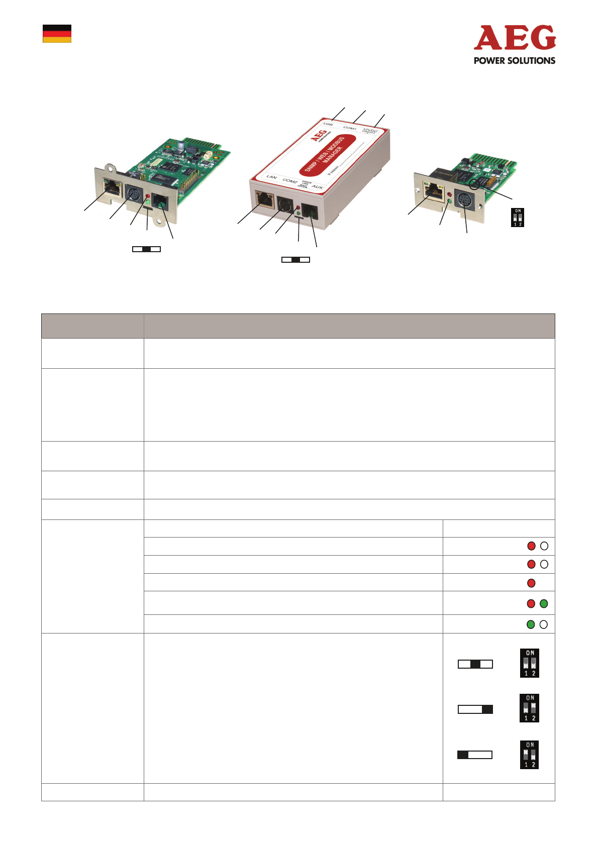
Beschreibung Funktion
1COM1-Anschluss Serielle Schnittstelle für den Anschluss einer USV oder anderen Endgeräten
mit dem original RS232-Kabel
2COM2-Anschluss
Für den Anschluss weiterer Geräte, wie z. B. GSM-Modem, Temperatur- und Feuchtesensor,
SENSORMANAGER_II, Feldbusgeräte (MODBUS RS232, Profibus, LONBus, etc.).
Anschluss bei SNMP Adapter Ext, SNMP-PRO Adapter, SNMP-mini Adapter = RS232
(nicht bei SNMP Adapter)
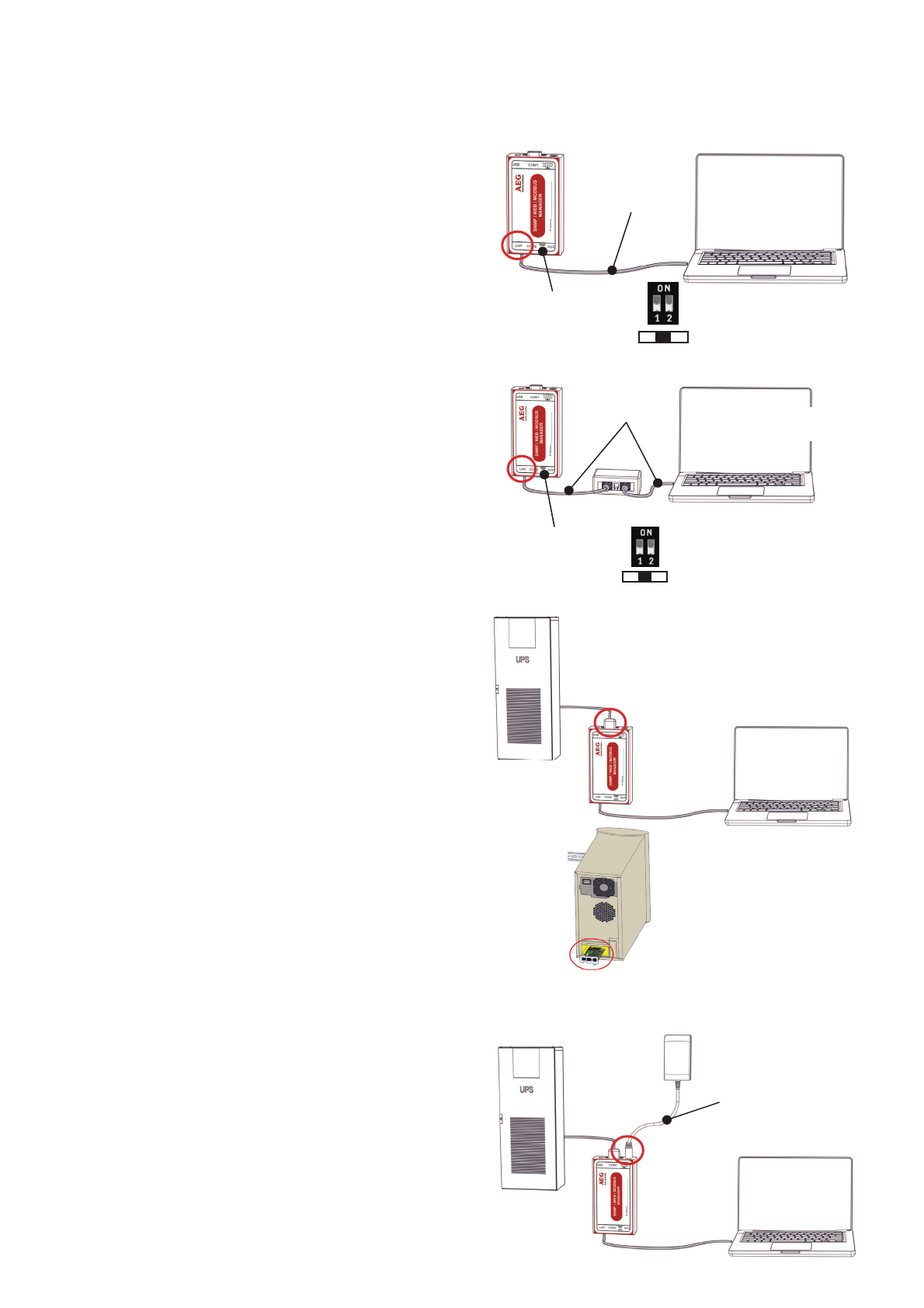
3LAN-Buchse RJ 45 Ethernet 10/100 Mbit Schnittstelle mit integrierten Status LED‘s
(Grüne LED: Verbindung ins Netzwerk besteht, Gelbe LED: Netzwerkaktivität)
4DC-Eingang Versorgung über 12VDC geregeltes Steckernetzteil extern,
DC-Stecker außen (-) Minus, innen (+) Plus
5AUX Bei SNMP Adapter Ext und SNMP-PRO Adapter Anschluss für CON_R_AUX4 und BACS
6Status-LEDs
(rot und grün)
Betriebszustand SNMP Adapter LED-Signalisierung:
Entpacken des Betriebssystems (Update-Vorgang) rot blinkend
Fehler beim Entpacken des Betriebssystems rot schnell blinkend
Bootphase des Betriebssystems rot lange an
Verbindung zu externem Gerät verloren (z. B. USV) rot und grün
Normalbetrieb—Verbindung zu externem Gerät aktiv grün blinkend
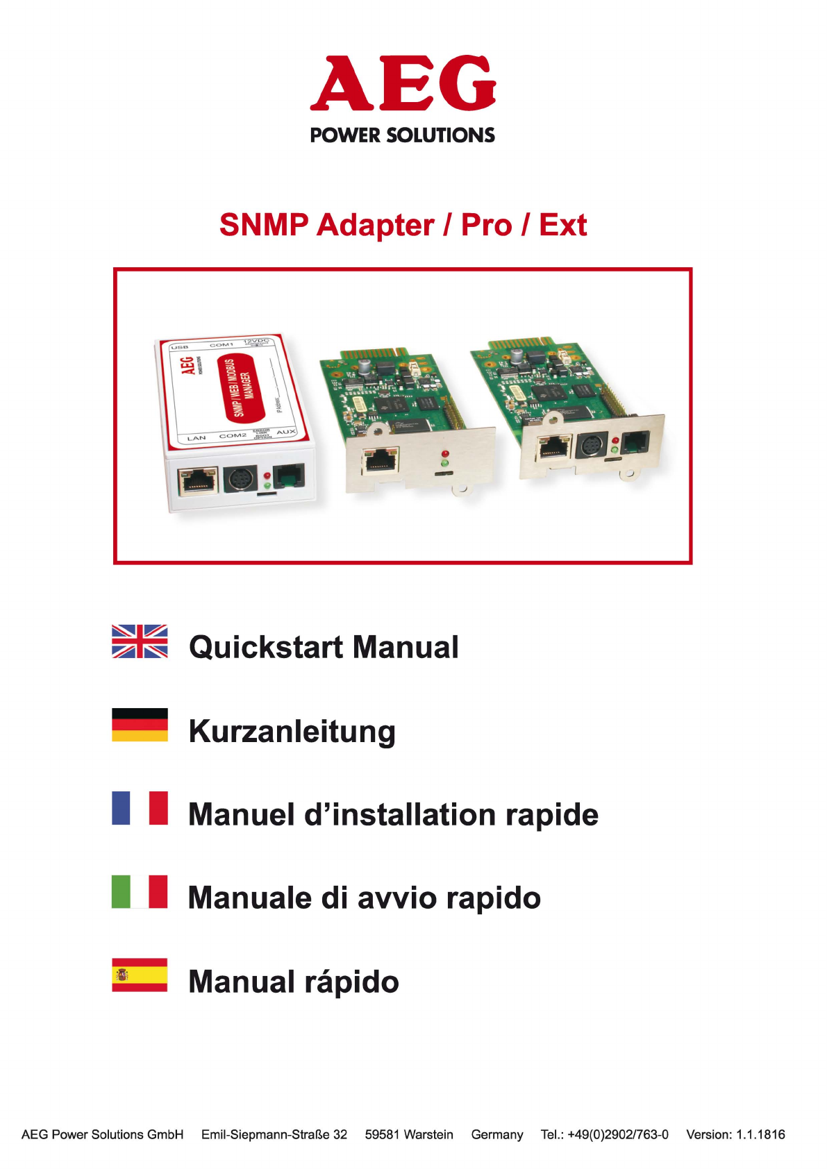
7Schiebeschalter
DIP Switch
Zur Umschaltung Konfigurations-/Betriebsmodus und DHCP
.
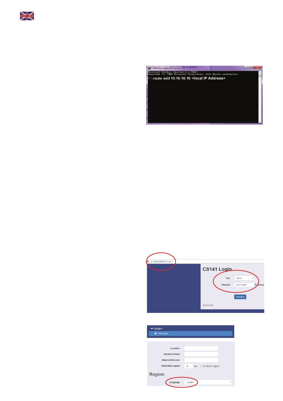
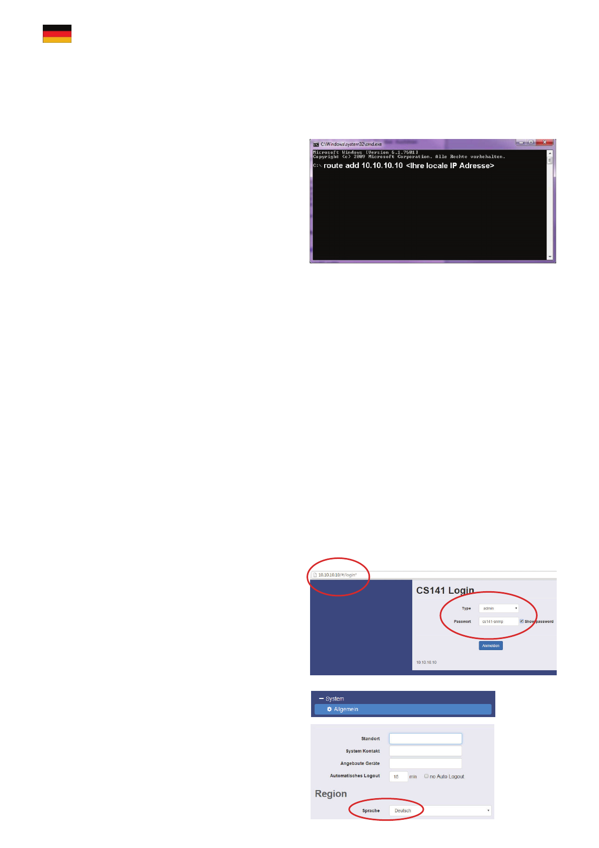
Schalterknopf mittig / 1 + 2 Position OFF: setzt den SNMP Adapter in
den Konfigurationsmodus und aktiviert die Standard IP-Adresse
10.10.10.10. nach einem Kaltstart.
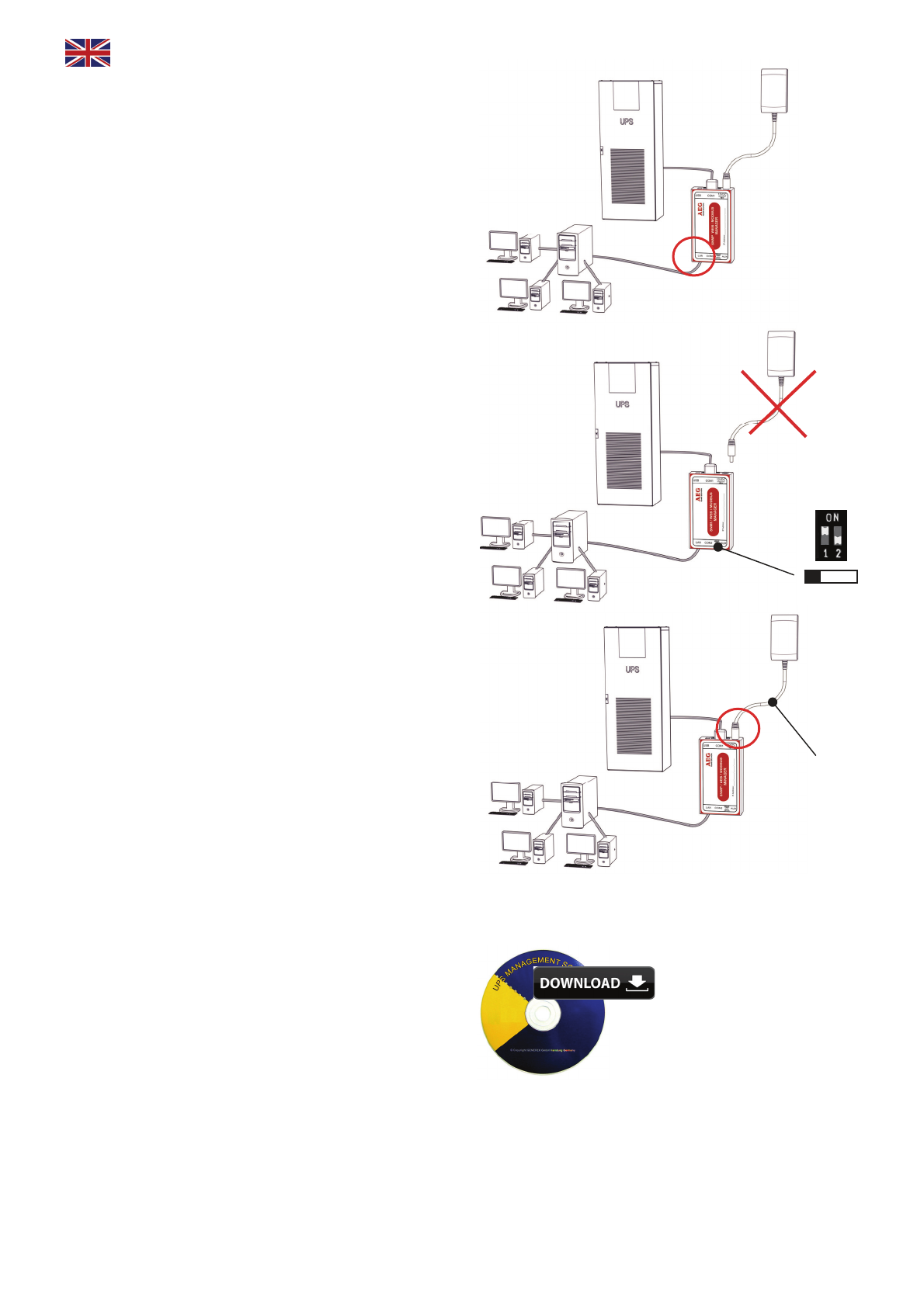
Schalterknopf rechts / 1 Position OFF + 2 Position ON: Automatische
IP Adressierung: DHCP ist aktiviert und eine IP Adresse wird automa-
tisch gesetzt. Prüfen Sie die MACAdresse von Ihrem SNMP Adapter, um
die IP- Adresse in der DHCP Server-Tabelle identifizieren zu können.
.
Schalterknopf links /1 Position ON + 2 Position OFF: Verwendung
der im HTTP-Interface konfigurierten Werte. Mit gesonderter Einstellung
auch DHCP möglich.
8USB
5
3 2 6 7 2
3 6
7
Slot
Version
Version: 2016-06-03
1
8 4
5
3 2 6 7
Externe
Version
SNMP-PRO Adapter SNMP Adapter Ext SNMP-mini Adapter
SNMP Adapter / Pro / Ext

Variante 1
1. Den Schiebeschalter in die Mitte / DIP SW 1 & 2 in
die Position OFF schieben.
2. Den SNMP Adapter mit einem Ethernet Cross
Cable über den LAN-Anschluss direkt an die PC/
Workstation-Netzwerkkarte anschließen.
Einstellungsempfehlung:
Den PC auf eine IP-Adresse aus dem gleichen Netz-
werk-Segment setzen, z.B. 10.10.10.11 UND als Ga-
teway 10.10.10.11 angeben.
Variante 2
1. Den Schiebeschalter in die Mitte / DIP SW 1 & 2 in
die Position OFF schieben.
2. Den SNMP Adapter und den PC mit einem Switch
oder Hub und zwei Ethernet-Kabeln über den LAN-
Anschluss verbinden.
Externe Version
Die USV mit dem seriellen original USV-Kabel an den
COM1-Port des SNMP Adapters verbinden.
Slot-Version
Bei Verwendung einer Slotkarte diese in den USV-
Steckplatz einschieben.
Für die Konfiguration einer USV verweisen wir auf
das “SNMP Adapter Benutzerhandbuch”, welches
Teil von der Dokumentations-CD ist oder als Down-
load von der Webseite des USV-Herstellers zur Ver-
fügung steht.
Alle USV-Funktionen und der allgemeine Ge-
brauch von flexiblen Events etc. sind in diesem
Handbuch separat beschrieben.
2. Adapter mit der USV verbinden
IP 10.10.10.10
DIP-Switch 1+2 = off
Schiebeschalter „mittig“
IP: 10.10.10.11
Subnet: 255.255.255
Gateway: 10.10.10.11
Ethernet
Cross
Kabel
Ethernet
Kabel IP: <Ihre IP-Adresse>
Gateway: <Ihr Gateway>
IP 10.10.10.10
DIP-Switch 1+2 = off
Schiebeschalter „mittig“
Hub/Switch
Stromversorgung
3. Den SNMP Adapter mit der Stromversorgung verbinden
Externe Version
Den SNMP Adapter mit dem mitgeliefertem Netzteil
an das Stromnetz anschließen.
Slot-Version
Ein Slot wird über die interne USV-Stromversorgung
mit Strom versorgt. Die Slot-Karte kann jederzeit in
die USV hineingesteckt bzw. entfernt werden ohne
diese zu beeinträchtigen.
Deutsch
German
Installation/Netzwerk-Integration vom SNMP Adapter
1. Konfigurationsmodus aktivieren

4.1. Route der Standard IP-Adresse auf Ihrem Computer hinzufügen
1. Öffnen einer “DOS Box” oder
2. Eingabe über Ausführen “cmd.exe”
3. Eingeben folgender Angabe:
„route add 10.10.10.10 <Ihre locale IP Adresse>”
(Beispiel: “route add 10.10.10.10 192.168.222.54” )
4. Einen Ping zu der SNMP Adapter-Adresse
10.10.10.10 absetzen und darüber die Weboberflä-
che aufrufen, um mit der Konfiguration zu beginnen.
Hinweis: Der interne Webserver benötigt für den ers-
ten Startvorgang des SNMP Adapters ca. 30 Sekun-
den. Wenn die USV-Status-LED von dauerrot
(Bootvorgang) auf grün blinkend wechselt, ist der
Webserver bereit.
1. Öffnen eines Webbrowsers.
2. Die Adresse http://10.10.10.10 eingeben.
3. Eingabe der Benutzerdaten im sich öffnenden
Login-Fenster.
User Name: „admin“
Standard-Passwort: „cs141-snmp“
5. Zugriff über HTTP-Verbindung und Login
4. Zugriff auf den SNMP Adapter über das Netzwerk einrichten
6. Sprache auswählen
1. Auf der Konfigurationsleiste auf den Punkt
- System
- Allgemein
klicken.
2. Die gewünschte „Sprache“ auswählen.

1. Auf der Konfigurationsleiste auf den Punkt
- System
- Netzwerk
klicken.
2. Die lokalen Parameter für
- Lokale Adresse
- Subnetzmaske
- Standard Gateway
(“DNS-Server”, wenn gewünscht) eingeben.
3. Auf “Übernehmen” klicken, um die Eingaben zu
bestätigen.
4. Den Button
- Dienste
- Zeitserver
betätigen.
5. Die gewünschte „IP-Adresse“ für einen Timeser-
ver-Service eingeben.
Die Timeserver-Einstellungen sind wichtig für die
Events/Alarms-Protokollierung mit Zeitstempel (wenn
der SNMP Adapter keinen Timeserver erreichen
kann, ist die Standardzeit der 01.01.2000 00:00).
6. Jeder Konfigurationsseite, auf der Veränderungen
vorgenommen wurden, muss mit “Übernehmen” be-
stätigt werden, um die Eingaben zu speichern.
7. Für die Konfiguration den Punkt
- Geräte/Anlagen
- USV
- Konfiguration
anklicken um das USV-Modell auszuwählen.
8. Das „USV-Modell“, welches mit dem SNMP
Adapter verbunden ist auswählen!
9. Auf “Übernehmen” klicken, um die Änderungen
zu speichern.
Weitere Informationen über die Eingabe der USV-
Einstellungen sind im SNMP Adapter Benutzerhand-
buch zu finden.
7. Konfiguration der IP-Adresse vom SNMP Adapter
Basis Netzwerk Einstellungen
Deutsch
German

Die LAN-Buchse des Adapters mit einem RJ45-Kabel
(nicht beiliegend) an das Netzwerk anschließen.
Der SNMP Adapter ist momentan noch auf der IP-
Adresse 10.10.10.10 erreichbar.
1. Um in den Betriebsmodus umzuschalten den
Schiebeschalter nach links / DIP SW 1 in die Position
ON schieben.
2. Für einen Cold-Boot die Stromversorgung vom
SNMP Adapter entfernen.
3. Den SNMP Adapter mit der Stromversorgung ver-
binden. Nach dem Starten ist er über die von Ihnen
konfigurierte IP-Adresse erreichbar und befindet sich
im Betriebsmodus.
(Die Adresse 10.10.10.10 ist nun nicht mehr erreich-
bar!)
10. Senden von Shutdown-Signalen an Computer im Netzwerk
Im Falle eines Stromausfalls können Computer im
Netzwerk durch ein Shutdown-Signal heruntergefah-
ren werden. Dafür muss auf jedem herunterzufahren-
den Rechner ein RCCMD-Client installiert werden.
Zusätzlich sind in der Ereignissteuerung des Adap-
ters einige Einstellungen vorzunehmen.
Installation des RCCMD-Client
1. Das Setup-Programm von einer UPS Manage-
ment Software CD oder aus dem Internet herunterla-
den.
2. Jede RCCMD-Installation erfordert einen eigenen
Lizenzschlüssel. Bei einigen Ausführungen ist bereits
eine Lizenz enthalten! Weitere Lizenzen sind bei Ih-
rem USV-Händler erhältlich.
http://www.aegps.com
- Products
- UPS Management Software
- Compu Watch
- Download
- Download selection
Netzwerk
8. Adapter mit dem Netzwerk verbinden
9. Umschalten in den Betriebsmodus
Strom-
versorgung
3. Im ersten Menü müssen Sie die IP-Adresse des
Adapters angeben, von dem der Client ein RCCMD
Shutdown-Signal erhalten soll. Bestätigen Sie die
folgenden Voreinstellungen und beachten Sie die
Shutdown-Datei im letzten Fenster. Um die aktuelle
Shutdown-Sequenz des Clients zu bearbeiten, drü-
cken Sie „Configure“. (Alternativ können Sie auch
direkt das Batchfile editieren, um Aktionen zu ändern
oder neu anzulegen.) Schließen Sie die Installation
mit „Install“ ab und der RCCMD-Dienst wird gestartet.

1. Für die Konfiguration das Menü
- Geräte/Anlagen
- USV
- Ereignisse
auswählen.
2. Im sich öffnenden Fenster auf den Button “+” ne-
ben dem Ereignis “Powerfail” klicken.
3. Im sich öffnenden Job Editor aus dem Drop-down
-Menü die Option “RCCMD Shutdown” auswählen.
4. Anschließend die „IP-Adresse“ des Clients ange-
ben (Der Listener-Port ist i.d.R. 6003).
Auf der rechten Seite kann der Zeitpunkt der Auslö-
sung des Shutdown-Signals eingestellt werden, z.B.
„At 300 seconds remaining time“.
5. Den Button „Konfiguration speichern“ drücken.
6. Aus Sicherheitsgründen empfehlen wir, dieselbe
Konfiguration des Ereignis „Powerfail“ auch im Ereig-
nis „Battery low“ vorzunehmen – dort jedoch ohne
Verzögerung, um zu vermeiden, dass der Server
durch einen niedrigen Batterieladezustand frühzeitig
ausschaltet.
Der SNMP Adapter kann mit einer Vielzahl von Um-
gebungssensoren und anderen Messgeräten kombi-
niert werden, um Temperatur, Luftfeuchtigkeit, Feuer
und Rauch, Bewegung und Einbruch, Druck, Füll-
stände etc. zu überwachen.
Zusätzlich sind weitere Zubehörteile wie verschiede-
ne Montagehalterungen, BACnet Converter, PROFI-
BUS Converter etc. erhältlich. Bitte fragen Sie Ihren
USV-Hersteller/-Lieferanten nach detaillierteren Infor-
mationen über die verfügbaren Optionen.
11. Konfiguration der Ereignissteuerung des Adapters SNMP Adapter
Deutsch
German
12. Optionen für den SNMP Adapter

description fonction
1COM1-Interface Interface série (câble RS232) pour la communication avec un onduleur ou un autre appareil
2COM2-Interface
Pour connecter des périphériques supplémentaires (par exemple le modem GSM,
le capteur d'humidité ou de température, le SENSORMANAGER II ou d’autres appareils
qui communiquent par le bus (par exemple Modbus-RS232, Profibus et LonBus, etc.)
Connexion SNMP Adapter Ext, SNMP-PRO Adapter, SNMP-mini Adapter (avec RS232 ).
Pas disponible pour SNMP Adapter.
3RJ45 interface LAN Interface Ethernet 10/100 Mbit avec des diodes d'état à LED
(couleur verte: indique que la connexion au réseau est établi,
couleur jaune: indique qu'il ya du trafic sur le reseau)
4DC entrée de
puissance
Dispositif externe: equipé d’un adaptateur de commutation de 12 V (livré avec l'appareil)
Dispositif interne: via l'interface de la fente de l'ASC
5AUX Disponible en tant que SNMP Adapter Ext et SNMP-PRO Adapter : il peut être connecté à
CON_R_AUX4 et BACS etc..
6Status-LED
(rouge et vert)
Etat de fonctionnement du SNMP Adapter signalisation LED
Déballage du système d'exploitation (processus de mise à jour) Diode rouge clignote
Erreur lors du déballage du système d'exploitation Diode rouge
clignote rapidement
Lancement du système d'exploitation Diode rouge fixe
Perte de la communication au dispositif externe (par exemple UPS) Diode clignote en
rouge et vert
Fonctionnement normal - Connexion avec un appareil externe est établi Diode clignote en vert
7Interrupteur à
glissière
Commutateur DIP
Pour la commutation entre les différentes options de démarrage
Interrupteur à glissière en position médiane / Commutateur DIP 1
+ 2 en position OFF: Pour mettre le SNMP Adapter en mode configu-
ration et activer l'adresse IP standard 10.10.10.10 (après un démarrage
à froid).
Interrupteur à glissière en position droite / DIP-Switch 1 Position
OFF, 2 Position ON:Adressage IP automatique : DHCP mode est
activé et l'adresse IP est défini par le serveur DHCP automatiquement.
Vérifiez l’adresse MAC de votre appareil (SNMP Adapter) pour identi-
fier votre appareil dans le réseau.
Interrupteur à glissière en position gauche / Commutateur DIP 1
en position ON, 2 position OFF: Les paramètres de réseau de l'inter-
face HTTP sont utilisés. Il est également possible de configurer le
mode DHCP.
8USB
5
3 2 6 7 2
3 6
7
Version
de slot
Version: 2016-06-03
SNMP Adapter / Pro / Ext
1
8 4
3 2 6 7
Externe
Version
SNMP-PRO Adapter SNMP Adapter Ext SNMP-mini Adapter

Variante 1
1. Placez le commutateur en position médiane / DIP
SW 1 et 2 en position OFF.
2. Connectez le port LAN du SNMP Adapter directe-
ment avec un câble Ethernet Croise au PC / poste
de travail.
Important:
Il est recommandé de donner au PC et au port
(gateway) la mème adresse IP, par exemple
10.10.10.11 .
Variante 2
1. Placez le commutateur en position médiane / DIP
SW 1 et 2 en position OFF.
2. Connectez le SNMP Adapter et le PC avec un hub
ou switch et deux câbles Ethernet sur le port LAN
de l'appareil.
Dispositif externe
Connectez l'onduleur avec le cable d’origine UPS au
COM1 du CS141.
Dispositif interne
Lors de l'utilization d'une carte interne insérer la dans
la fente de l'UPS prévue à cet effet.
Pour l'installation de l'onduleur, veuillez lire le manuel
qui est inclus dans le CD ou la documentation qui
peut être téléchargée sur la page internet du fabricant
de votre UPS.
Toutes les fonctions de l'onduleur et l'utilisation
d'événements flexibles, etc., sont décrits dans le
Manuel de l'utilisateur du SNMP Adapter !
2. Connectez l'adaptateur à l'ASC
IP 10.10.10.10
Interrupteur en position médiane
Commutateur DIP 1 + 2 = off
IP: 10.10.10.11
Subnet: 255.255.255
Gateway: 10.10.10.11
Ethernet
cross
cable
Ethernet
cables IP: <Your IP Address>
Gateway: <Your Gateway>
IP 10.10.10.10
Interrupteur en position médiane
Commutateur DIP 1 + 2 = off
Hub/Switch
Power Supply
3. Connectez le SNMP Adapter à l'alimentation
Dispositif externe
Connectez le SNMP Adapter à l'alimentation fournie.
Dispositif interne
Le SNMP Adapter recoit du courant à travers l'ali-
mentation interne de l'onduleur. Il est toujours possib-
le d'insérer ou de retirer le SNMP Adapter sans endo-
mmager l'onduleur. Pour déconnecter la carte, retirez
le périphérique de la fente et placez-le à nouveau.
Français
French
Installation / Intégration au réseau du SNMP Adapter
1. Activer le de mode de configuration

4.1. Ajouter l'adresse IP standard sur votre ordinateur
1. Ouvrez un „DOS command“ fenêtre ou
2. Exécutez la commande „cmd.exe“
3. Entrez la commande suivante:
„Route add 10.10.10.10 <adresse IP locale“
(par exemple: „route add 10.10.10.10
192.168.222.54")
4. Exécutez la commande „ping 10.10.10.10" pour
vérifier si l'appareil est accessible.
Conseils: Le SNMP a besoin d'environ 30 secondes
pour démarrer le serveur web. Quand le serveur Web
fonctionne, la diode change de couleur du rouge en
vert (démarrage) et se met à clignoter.
1. Ouvrez le navigateur de Web.
2. Entrez l'adresse http://10.10.10.10
3. Pour la connexion choisir:
nom d'utilisateur: „admin“
mot de passe par défaut: „cs141-snmp“
5. Accès via une connexion HTTP et login
4. Accès au SNMP Adapter via le réseau
6. Choisissez la langue
1. Alley sur
- Système
- Général
dans le menu à gauche.
2. Ensuite choisissez la „langue“.

1. Choisissez
- Système
- Réseau
dans le menu à gauche.
2. Entrez les valeurs de
- Adresse Locale
- Masque de sous-réseau
- Portail par Défaut
("Serveur DNS" si désiré)
3. Appuyez sur le bouton „Appliquer“ pour valider
les modifications.
4. Choisissez
- Service
- Serveur de temps
dans le menu déroulant.
5. Entrez „l'adresse IP“ de votre serveur de synchro-
nisation et synchronisez le CS141 avec ce serveur.
Les paramètres temporels du serveur sont importants
pour l'enregistrement / d'alarme d’un événement (Si
aucun serveur de synchronisation est configuré le
temps sera mis à 01.01.2000.
6. Configure les modification en appuyant sur le bou-
ton „Appliquer“.
7. Choisissez les points
- Appareils
- ASC
- Configuration
dans le menu déroulant pour la configuration d' ASC.
8. Choisissez le modèle ASC qui est relié avec le
SNMP Adapter.
9. Cliquez sur le bouton „Appliquer“ pour enregistrer
les modifications.
Plus d'informations sur le paramètre d‘ ASC sont
disponibles dans le CS 141 Mode d'emploi.
7. Configurez l'adresse IP du SNMP Adapter
Paramètres réseau de base
Français
French

Raccordez le port LAN de l'appareil avec un câble
réseau RJ45 (non inclus) au réseau.
Pour le moment le SNMP Adapter est toujours acces-
sible sur l'adresse IP 10.10.10.10!
1. Pour changer le mode de fonctionnement, déplac-
er le commutateur vers la gauche / DIP-Switch 1 en
position ON.
2. Pour un démarrage à froid (Cold-Boot) retirer l'ali-
mentation électrique du SNMP Adapter.
3. Ensuite connectez le SNMP Adapter à l'alimenta-
tion à nouveau. Le SNMP Adapter sera joinable à
l'adresse IP configurée. (L'adresse n’est plus accessi-
ble à 10.10.10.10)
10. Envoyez signales d'arrêt aux ordinateurs sur le réseau
Pour arrêter un ordinateur en cas de panne de
courant, il est nécessaire d'installer un client RCCMD
à chaque ordinateur qui doit etre arreté. En outre il y
à certaines configurations à faire dans la gestion de
l'événement de l'adaptateur.
Installation du client RCCMD
1. Télécharger le fichier d'installation de l'ASC-
Management CD ou de Internet.
2. Chaque installation RCCMD nécessite une clé de
licence distinct. Pour certains produits, une clé de
licence est inclus. Licences supplémentaires sont
disponibles chez votre fournisseur.
Network
8. Connectez le SNMP Adapter avec le réseau
9. Mettre le SNMP Adapter en mode
de fonctionnement
Power Supply
3. Dans le premier menu, vous devez entrer
l'adresse IP de l'adaptateur dont le client de RCCMD
doit recevoir les signaux d'arrêt. Validez la configura-
tion par défaut suivant. Remarquez le fichier d'arrêt
dans la dernière fenêtre. Pour modifier la séquence
d'arrêt du client, appuyez sur le bouton "configure" (Il
est également possible d'éditer le fichier batch pour
modifier ou ajouter des événements.) L'installation se
termine en appuyant sur "Install" et le service dé-
marre.
http://www.aegps.com
- Products
- UPS Management Software
- Compu Watch
- Download
- Download selection

1. Choisissez l'entrée
- Appareils
- ASC
- Évènements
dans le menu déroulant.
2. Cliquez sur le bouton "+" à côté de l'événement
"Powerfail".
3. Le Job-Editor démarre. Choisissez l'option
“RCCMD Shutdown” dans le menu.
4. Saisissez „l'adresse IP“ de votre client (Le Liste-
ner-Port est habituellement 6003). Sur le côté droit,
vous pouvez spécifier quand le signal doit être arrêté,
par exemple „At 300 seconds remaining time“.
5. Cliquez sur le bouton „Sauvegarder la Configu-
ration“.
6. Pour des raisons de sécurité, nous vous recom-
mandons de faire un RCCMD d'arrêt en cas de
“panne de courant” ("Power Fail") comme dans le
cas de "batterie faible" - mais, dans ce cas, sans
aucun retard pour éviter que les pannes de serveur
aient raison de l'alarme de batterie faible.
Le SNMP Adapter peut être complète par une variété
de capteurs d’environnement et d’autres dispositifs
pour surveiller température, humidité, feu et fumée,
mouvement et intrusion, pression, niveaux de replis-
sage etc.
En outre, d'autres composants tels que de divers fixa-
tions de montage, BACnet convertisseur,, PROFI-
BUS convertisseur etc. disponibles. S'il vous plaît
demandez à votre ASC fabricants / fournisseurs pour
d’informations plus détaillées sur les options disponi-
bles.
11. Configuration de l'événement pour le SNMP Adapter
12. Options pour SNMP Adapter
Français
French

Descrizione Funzione
1Interfaccia COM1 Interfaccia seriale per connettere un UPS (gruppo di continuità), o un altro dispositivo compatibile,
utilizzando il cavo RS232 originale fornito in dotazione al dispositivo stesso.
2Interfaccia COM2
Interfaccia per collegare dispositivi aggiuntivi, ad esempio: modem GSM, sensore di temperatura e
umidità, SENSORMANAGER_II, dispositivi “fieldbus” (MODBUS, Profibus, LONBus, etc.)
RS232: disponibile in SNMP Adapter Ext, SNMP-PRO Adapter, SNMP-mini Adapter
Non disponibile in SNMP Adapter
3Interfaccia LAN RJ45 Interfaccia Ethernet 10/100 Mbit con LED di stato integrati
(LED verde: collegamento fisico alla rete; LED giallo: traffico di rete).
4Ingresso
alimentazione
Dispositivo esterno: fornita da un alimentatore switching a 12V (incluso nella confezione)
Dispositivo interno: fornita direttamente dall‘interfaccia slot del dispositivo interfacciato
5Connettore AUX Disponibile in SNMP Adapter Ext e SNMP-PRO Adapter
Permette il collegamento di accessori come ad esempio CON_R_AUX4 e BACS.
6LED di stato
(rosso e verde)
Stato di funzionamento SNMP Adapter LED di notifica
Estrazione del Sistema Operativo (procedura di aggiornamento) rosso lampeggiante
Errore durante l'estrazione del Sistema Operativo rosso lampeggiante
veloce
Avvio del Sistema Operativo (fase di boot) rosso acceso fisso
Comunicazione interrotta con il dispositivo collegato (esempio un UPS) rosso e verde
accesi fissi
Funzionamento normale - comunicazione in corso con il dispositivo verde lampeggiante
7Selettore
DIP Switch
Per la selezione delle diverse opzioni di avvio
.
Selettore posizione “centrale” / DIP Switch (1 = OFF ; 2 = OFF):
imposta il SNMP Adapter in modalità di configurazione e attiva l'indiriz-
zo IP predefinito 10.10.10.10. (dopo aver spento e riacceso il SNMP
Adapter).
Selettore posizione “destra” / DIP Switch (1 = OFF ; 2 = ON):
modalità DHCP, l'IP viene impostato dal server DHCP. Controllare
l’indirizzo MAC del SNMP Adapter per la sua identificazione nella rete.
Selettore posizione “sinistra” / DIP Switch (1 = ON ; 2 = OFF):
vengono utilizzate le impostazioni di rete configurate tramite
l'interfaccia HTTP del SNMP Adapter (da cui è anche possibile confi-
gurare la modalità DHCP).
8USB
5
3 2 6 7 2
3 6
7
Versione
Slot
Version: 2016-06-03
SNMP Adapter / Pro / Ext
1
8 4
5
3 2 6 7
Externe
Version
SNMP-PRO Adapter SNMP Adapter Ext SNMP-mini Adapter
This manual suits for next models
2
Table of contents
Languages: