6
Hob burners
Tolightaburner:
zPush in the relevant control knob and turn it to
maximumposition.
zUponignition,keeptheknobpusheddownabout
5 seconds. This will allow the "thermocouple"
(fig.1-letterD)tobeheatedandthesafetydevice
tobeswitchedoff,otherwise thegassupplywould
beinterrupted.
zThenadjusttheflameasrequired.
zIftheburnerdoesnotignite,turnthecontrolknob
tozero,andtryagain.
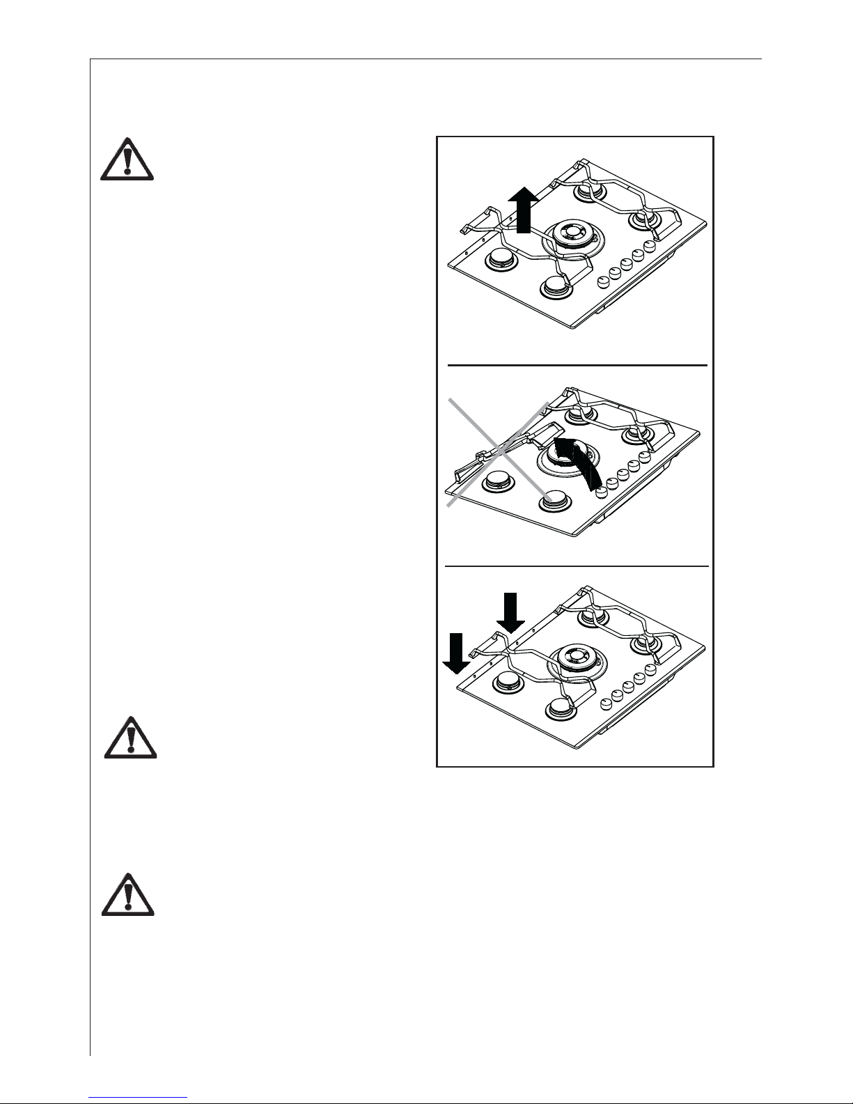
zIf you cannot light the flame even after several
attempts,checkthe"cap"(lett.A)andthe"crown"
(lett.B)areinthecorrectposition.
Each control knob is equipped with a pilot light
which gradually lights up according to the heat
levelthatyouselectwiththecontrolknob.
Whenswitchingonthemains,afterinstallationora
powercut,itisquitenormalforthesparkgenerator
tobeactivatedautomatically.
Operation
As soon as a liquid starts boiling, turn down the
flamesothatitwillbarelykeeptheliquidsimmering.
If you use a saucepan which is smaller than the
recommendedsize,theflamewillspreadbeyond
the bottom of the vessel, causing the handle to
overheat.
Take care when frying food in hot oil or fat,
as the overheated splashes could easily ignite.
Ifthecontrolknobsbecomedifficulttoturn,pleasecontactyourlocalServiceForceCentre.
Intheabsence ofelectricity,ignition canoccurwithout theelectricaldevice; inthiscase
approachtheburnerwithaflame,pushtherelevantknobdownandturnitanti-clockwiseuntil
itreachesthe"maximum"position.
))
))
)
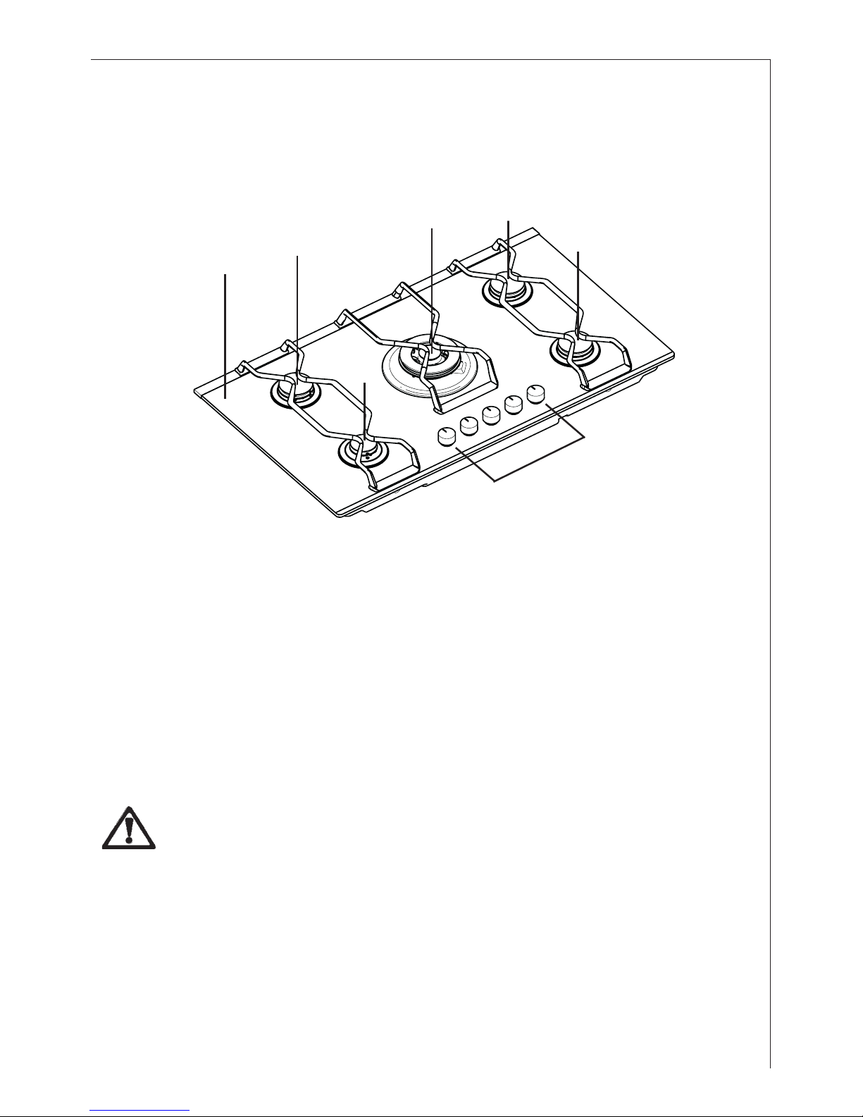
A- Burner cap
B- Burner crown
C- Ignition electrode
D- Thermocouple
triple crown
burner
A
B
D
C