AEG DUA2.1 Quick start guide

Numerical Voltage Protection Relay
Technical Guide and user manual
HF9024 (DUA2.1)

Technical Guide and
user manual
Contents
CONTENTS
Handling, Installation and Case Dimensions
User Guide
Menu Content Tables
Technical Data and Curve Characteristics
Application Guide
NUMERICAL Voltage Relay
Introduction
HF9024

Introduction
5
HF9024
CONTENTS
1. INTRODUCTION 2
2. HOW TO USE THIS MANUAL 3
3. INTRODUCTION TO THE HF9024 4
4. MAIN FUNCTIONS

Introduction
1. INTRODUCTION
The Voltage relay type HF9024 is a numerical relay .
HF9024

Introduction
HF9024
HF9024
2. HOW TO USE THIS MANUAL
This manual provides a description of HF9024 functions and settings. The goal of
this manual is to allow the user to become familiar with the application,
installation, setting and commissioning of the relay.
This manual has the following format:
HF9024 Introduction
Contents of the manual and general introduction to the relay
HF9024 Handling, installation and case dimensions
Precautions to be taken when handling electronic equipment.
HF9024 User Guide of the relay as
A detailed description of the features
HF9024 Technical data and Comprehensive details
on nominal values, setting ranges,
Specifications.
HF9024 Commissioning and Maintenance Guide
Guide to commissioning, problem solving and maintenance of
HF9024 Connection diagrams for the relay
HF9024 Commissioning test records
HF9024 Hardware/Software version history
HF9024 Communication mapping data bases

Introduction
HF9024
HF9024
3. INTRODUCTION TO THE RELAY
The HF9024 relay provide comprehensive Voltage fault protection for utilities
networks, industrial plants and networks as well as for other applications where
Voltage protection is required.
In addition to its protective functions, each relay offers control and recording
features. They can be fully integrated to a control system so protection, control,
data acquisition and recording of faults, events and disturbances can be made
available.
The relay is equipped on the front panel with a liquid crystal display (LCD) with 2
x 16 back-lit alphanumerical characters, a tactile 7 button keypad (to access all
settings, clear alarms and read measurements) and 11 LEDs that indicate the
status of the relay.
In addition, the use of the RS485 communication port by using protocol mode
bus makes it possible to read, reinitialize and change the settings of the relay, if
required, from a local or remote PC computer loaded with software.
Its flexibility of use, reduced maintenance requirements and ease of integration
allow the Relay to provide an adaptable solution for the problems of the
protection electric networks.

Introduction
4. MAIN FUNCTIONS
The following table shows the functions available for HF9024 relay.
PROTECTION FUNCTIONS OVERVIEW
HF9024
Configuration depending on the number
and type of voltage transformers
Phase-to-neutral or phase-to-phase voltage protection
27
Phase under voltage (AND/OR logic)
59
Phase over voltage (AND/OR logic)
59N
Zero sequence over voltage
47
Negative sequence over voltage
-
Remote communication (RS485 port)
Local communication (RS232 port)
Event recording
250
Fault recording
25
Disturbance recording
5
Setting group
1
Circuit Breaker Control
Output relay latching
HF9024
27D Positive sequence under voltage -
Delta U / Delta T
Blocking logic
Balance voltage -
Digital inputs 2
Output relays 6

Handling, Installation and Case Dimensions
HANDLING, INSTALLATION
AND CASE DIMENSIONS
HF9024

Handling, Installation and Case Dimensions
CONTENTS
1. GENERAL CONSIDERATIONS 2
1.1 Receipt of relays 2
1.2 Electrostatic discharge (ESD) 2
2. HANDLING OF ELECTRONIC EQUIPMENT 3
3. RELAY MOUNTING 4
4. UNPACKING 5
5. STORAGE 6
6. DIMENSIONS 7
7. Communication 8
7.1 RS232 Port 8
7.2 RS485 port 8
8. Earthing 8
HF9024

Handling, Installation and Case Dimensions
1. GENERAL CONSIDERATIONS
1.1 Receipt of relay
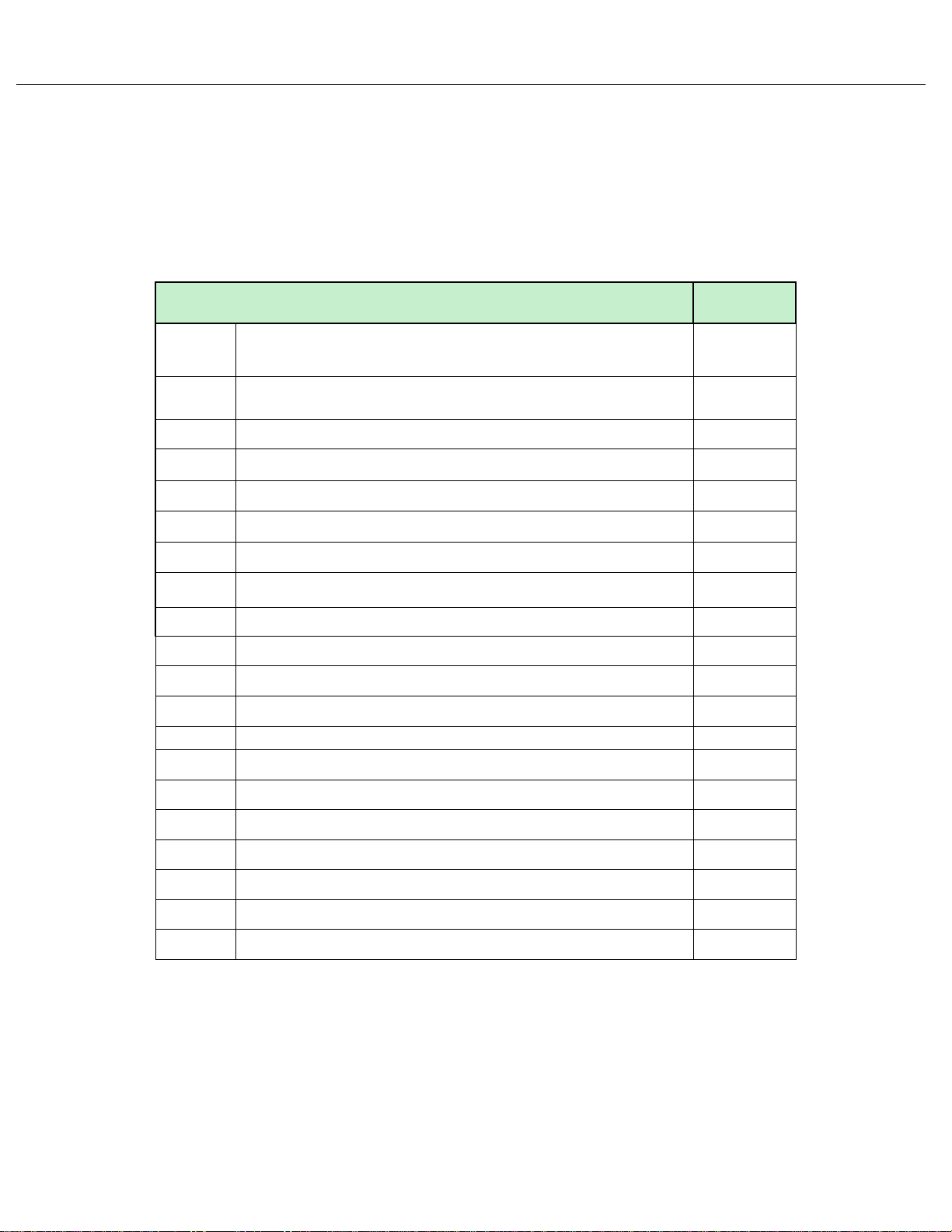
Protective relay, although generally of robust construction, require careful
treatment prior to installation on site. Upon receipt, relay should be examined
immediately to ensure no damage has been sustained in transit. If damage has
been sustained during transit a claim should be made to the transport
contractor and HAMIANFAN should be promptly notified.
1.2 Electrostatic discharge (ESD)
The relay use components that is sensitive to electrostatic discharges.
The electronic circuits are well protected by the metal case and the internal
module should not be withdrawn unnecessarily. When handling the module
outside its case, care should be taken to avoid contact with components and
electrical connections. If removed from the case for storage, the module should
be placed in an electrically conducting antistatic bag.
There are no setting adjustments within the module and it is advised that it is
not unnecessarily disassembled. Although the printed circuit boards are
plugged together, the connectors are a manufacturing aid and not intended for
frequent dismantling; in fact considerable effort may be required to separate
them. Touching the printed circuit board should be avoided, since
complementary metal oxide semiconductors (CMOS) are used, which can be
damaged by static electricity discharged from the body.
HF9024

Handling, Installation and Case Dimensions
2. HANDLING OF ELECTRONIC EQUIPMENT
A person’s normal movements can easily generate electrostatic potentials of
several thousand volts. Discharge of these voltages into semiconductor devices
when handling electronic circuits can cause serious damage, which often may
not be immediately apparent but the reliability of the circuit will have been
reduced.
The electronic circuits are completely safe from electrostatic discharge when
housed in the case. Do not expose them to risk of damage by withdrawing
modules unnecessarily.
Each module incorporates the highest practicable protection for its
semiconductor devices.
However, if it becomes necessary to withdraw a module, the following
precautions should be taken to preserve the high reliability and long life for
which the equipment has been designed and manufactured.
1. Before removing a module, ensure that you are at the same electrostatic
potential as the equipment by touching the case.
2. Handle the module by its front plate, frame or edges of the printed circuit
board. Avoid touching the electronic components, printed circuit track or
connectors.
3. Do not pass the module to another person without first ensuring you are both
at the same electrostatic potential. Shaking hands achieves equal potential.
4. Place the module on an antistatic surface, or on a conducting surface which
is at the same potential as yourself.
5. Store or transport the module in a conductive bag. If you are making
measurements on the internal electronic circuitry of an equipment in service, it
is preferable that you are earthed to the case with a conductive wrist strap.
Wrist straps should have a resistance to ground between 500kΩ–10MΩ. If a
wrist strap is not available you should maintain regular contact with the case to
prevent a build-up of static. Instrumentation which may be used for making
measurements should be earthed to the case whenever possible.
More information on safe working procedures for all electronic equipment can
be found in BS5783 and IEC147. It is strongly recommended that detailed
investigations on electronic circuitry or modification work should be carried out
in a special handling area such as described in the above-mentioned BS and
IEC documents.
HF9024

Handling, Installation and Case Dimensions
3. RELAY MOUNTING
The relay is dispatched either individually or as part of a panel/rack assembly.
Modules should remain protected by their metal case during assembly into a
panel or rack.
For individually mounted relays an outline diagram is supplied in following of this
chapter showing the panel cut-outs and hole centers.
HF9024

Handling, Installation and Case Dimensions
HF9024
4. UNPACKING
Care must be taken when unpacking and installing the relay so that none of the
parts is damaged or the settings altered. The relay must only be handled by
skilled personnel. The installation should be clean, dry and reasonably free from
dust and excessive vibration. The site should be well lit to facilitate inspection.
The relay that has been removed from the case should not be left in a situation
where that is exposed to dust or damp. This particularly applies to installation
which is being carried out at the same time as construction work.

Handling, Installation and Case Dimensions
5. STORAGE
If relay is not to be installed immediately upon receipt they should be stored in a
place free from dust and moisture in their original cartons. Where de-humidifier
bags have been included in the packing they should be retained. The action of
the de-humidifier crystals will be impaired if the bag has been exposed to
ambient conditions and may be restored by gently heating the bag for about an
hour, prior to replacing it in the carton.
Dust which collects on a carton may, on subsequent unpacking, find its way into
the relay; in damp conditions the carton and packing may become impregnated
with moisture and the de-humidifier will lose its efficiency.
Storage temperature: –25°C to +70°C.
HF9024

Handling, Installation and Case Dimensions
102.4
HF9024
6. CASE DIMENSIONS
The relay is available in a 4U metal case for panel or flush mounting.
Weight: 1.8 Kg External size : Height case 152 mm
Front panel 177 mm Width case 97 mm
Front panel 103 mm Depth case 226 mm
Front panel + case 252 mm

Handling, Installation and Case Dimensions
7. Communication
7.1 RS232 Port
In the bottom of the front panel, there is a RS232 port, The communication with
a computer through the RS232 allows access to the relay all information and
setting. It makes the access and changes of any information, setting and
configuration.
You can see all events and records by this port on monitor of computer we will
explain it by details in the next sections.
7.2 RS485 port
Connections to RS485 are made using annular terminals. It is recommended that
a two core screened cable, is used with a maximum total length of 1000 m or
a200nF total cable capacitance.
Typical specification:
−Each core: 16/0.2 mm copper conductor, PVC insulated.
−Nominal conductor area: 0.5 mm² per core
−Screen: Overall braid, PVC sheathed
−Linear capacitance between conductor and earth: 100pF/m
8. Earthing
Each equipment must be connected to a local earth terminal by the intermediary
of a M4 earth terminal. We recommend a wire of minimal section of 2.5 mm², with
annular terminals on the side of the equipment. Because of the limitations of the
annular terminals, the possible maximum section is of 6mm² by wire. If a larger
section is necessary, one can use cables connected in parallel, each one ending
with an annular terminal separated on the side of the equipment. One can also
use a metal bar.
NOTE: To prevent any electrolytic risk between copper conductor or brass
conductor and the back plate of the equipment, it is necessary to take
precautions to isolate them one from the other. This can be done in several
ways, for example by inserting between the conductor and the case a plated
nickel or insulated ring washer or by using a tin terminals.
HF9024

User Guide
User Guide
HF9024

User Guide
2. USER INTERFACE 3
2.1 LCD display and keypad description 4
2.1.1 LCD display 4
2.1.2 Keypad 4
2.2 LEDs 5
2.3 Description of the two areas under the top and bottom flaps 6
3. PASSWORD 7
3.1 Password protection 7
3.1.1 Password entry 7
3.1.2 Changing the password 7
3.1.3 Change of setting invalidation 8
4. DISPLAYS OF ALARM & WARNING MESSAGES 8
4.1 Electrical Network Alarms 8
4.2 Relay Hardware or Software Warning Messages 10
HF9024
CONTENTS
1. PRESENTATION OF HF9024 RELAY 2

User Guide
HF9024
1. PRESENTATION OF HF9024 RELAY
This relay is fully numerical relays designed to perform electrical protection and
control functions.
HF9024 relay is powered either from a DC or an AC auxiliary power supply.
Using the front panel, the user can easily navigate through the menu and access
data, change settings, read measurements, etc.
Eleven LEDs situated in the front panel help the user to quickly know the status
of the relay and the presence of alarms. Alarms that have been detected are
stored and can be displayed on the back-lit LCD.
Any short time voltage interruption (<50ms) is filtered and regulated through the
auxiliary power supply.
HF9024 relay have 3 phase inputs available for 1 and 5 Amps rated CTs. On
each one of these relay.
HF9024 relay continuously measure phase and earth currents and take into
account the true RMS current value up to 10th harmonic (at 50 Hz).
Output relays are freely configurable and can be activated by any of the control
or protection functions available in the relay. Logic inputs can also be assigned to
various control functions.
On their rear terminals HF9024 have a standard RS485 port available. When
ordering, the user can choose between the following communication protocol:
ModBus RTU.
Using RS485 communication channel, all stored information (measurements,
alarms, and parameters) can be read and settings can be modified when the
chosen protocol allows it.
HF9024 relay can be connected directly to a digital control system. All the
available data can then be gathered by a substation control system and be
processed either locally or remotely.

USER INTERFACE
2.
values and alarm and to clearly display the status of the relay.
The front panel of the relay has three separate sections:
The LCD display and the keypad
1.
The LEDs
2.
The two zones under the upper and lower flaps
3.
2 buttons to read and
Clear alarms messages
5 buttons to modify the
setting and read vaues
2 × 16 alphanumerical
backlit display
Trip led
Alarm led
Warning led
Power led
Figure 1: Front panel
Programmable led
User Guide
HF9024
HF9024 relay from panel allows the user to easily enter relay settings, display measured
RS 232
This manual suits for next models
1
Table of contents