manuals.online logo
Brands
  1. Home
  2. •
  3. Brands
  4. •
  5. AEM
  6. •
  7. Other
  8. •
  9. AEM 21-8016 Service manual

AEM 21-8016 Service manual

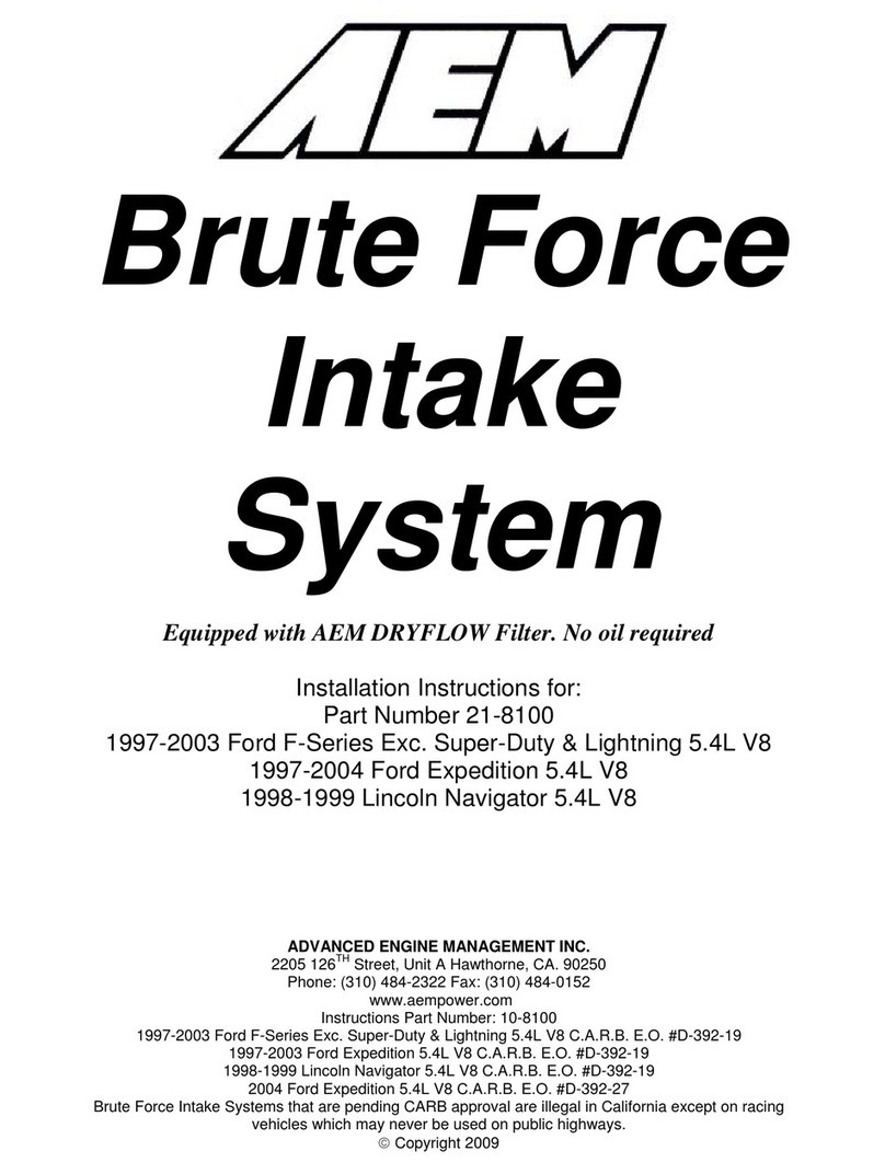
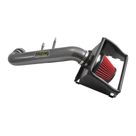
Brute Force
Intake
System
Equipped with AEM DRYFLOW Filter. No oil required
Installation Instructions for:
Part Number 21-8016
2004 Pontiac GTO
5.7L LS1 V8
ADVANCED ENGINE MANAGEMENT INC.
2205 126TH Street, Unit A Hawthorne, CA. 90250
Phone: (310) 484-2322 Fax: (310) 484-0152
www.aempower.com
Instruction Part Number: 10-8016
2004 Pontiac GTO LS1 V8 C.A.R.B. E.O. #D-392-28
Brute Force Air Intake Systems that are pending CARB approval are illegal in California except on racing vehicles which may never
be used on public highways.
©Copyright 2008
2
Congratulations! You have just purchased the finest Air Induction & Filtration system for your truck at any price!
The AEM Brute Force System is the result of extensive development on a wide variety of trucks. It is the most
advanced short pipe air intake system on the market. Each system is specifically engineered for its particular
application. All AEM Brute Force Systems deliver maximum performance gains through lightweight, all-aluminum,
mandrel-bent tubing that is tuned in both length and diameter. The aluminum will not crack in extended use like
plastic. The tube length and diameter are matched for each specific engine to give power over a broad RPM range.
Unlike plastic systems that use a continually diverging cross-section, we take advantage of the acoustical energy in
the inlet duct to promote cylinder filling during the intake valve-opening event. Every intake is coated with a high-
gloss, heat-reducing Zirconia based powder coating. This special blend of powder coating helps reduce heat
penetration, which in turn reduces the temperature of the inlet air charge. The cooler inlet air temperature translates
to more power during the combustion process because cool air is denser than warm air. The air mass flow to the
engine is increased because of the increased airflow and reduced inlet temperature, which translates to more power.
Bill of Materials for: Part #21-8016
Quantity Part Number Description
1 2-80161 Intake Pipe
1 2-80162 Intake Pipe
1 20-8016 Heat Shield
1 21-205D Air Filter Assembly 4.0 x 5"
4 1-3028 Washer, 1/4 SAE Flat
2 1-2014 Bolt, 1/4-20 x 3/4"
2 1-2074 Lock Nut, '1/4-20
1 784634 1/2" Grommet
1 784633 3/8" Grommet
1 5-435 3.5-4 reducing coupler
1 103-BLO-5620 Hose Clamp,3.56-4.50"
3 103-BLO-6420 Hose Clamp,4.00-5.00"
1 5-490 Hose,elbow 4.0" X 4.0" Tight 90
4" 8-111 Rubber Edge Trim
12" 8-119 Sponge Rubber Gasket
1 1228560 Mount,Rubber 1" X 8MM
2 559960 Washer M8
2 444.460.08 Nut,Nylok 8MM
2 1-127 Zip tie for heatshild
1 10-8016 Kit Instructions
2 10-922S AEM Silver Decal
Read and understand these instructions BEFORE attempting to install this product.
Note: This inlet pipe kit requires the removal and reinstallation of emissions related
components. If you are not familiar with the installation and/or the operation of these
components then please refer this installation to a qualified professional.
1) Getting started
a) Make sure vehicle is parked on a level surface.
b) Set parking brake.
c) Disconnect negative battery terminal.
d) If engine has run within the past two hours let it cool down.
2) Removing the stock air inlet system
3
a) Before removing any of the O.E. components, label
each individual part so that no components
become mixed up during the installation process.
Remove the radiator shroud from the front of the car
by removing the 5 plastic conncectors.
b) Loosen the Hose clamps on the rubber elbow
attached to the throttle body and the Mass Air Flow
(MAF) sensor. Unplug the IAT sensor and remove the
inlet tube.
c) Loosen the hose clamp securing the MAF
adapter to the air filter housing. Unplug the wiring
harness from the MAF sensor and remove
sensor.
d) Detach the wiring harness air filter housing as
shown.
Hose Clam
p
s
MAF Sensor
4
e) Loosen the three screws holding the top of the air
filter housing to the filter box and remove the top.
Next, remove the air filter from inside the box.
f) The coolant reservoir is held in place by two
grommets. Move it by lifting it off the two posts that
secure it and set it aside but do not disconnect it..
g) With the coolant reservoir out of the way, remove
the lower half of the air filter housing by gently lifting it
up. This is held in place with grommets similar to the
coolant reservoir.
h) Remove the air shield by bending it slightly and
pulling it towards the shock tower.
i) Unplug the IAT sensor from the stock intake tube.
The best way to do this is to pull straight back while
twisting gently.
j) Remove the bolt shown on the inner fender. This
bolt will be reinstalled later
Bolt on Inner Fender
3) Installing the AEM BFS Intake
5
a) On the radiator support there are two holes. Behind
these is a plastic panel that needs to be drilled out to
match the metal holes.
b) Install the rubber grommet into the hole in the heat
shield as shown.
c) Route the wires for the IAT, MAF, and ACPT such
that they are in front of the AC line but behind the
radiator support as shown.
d) Install the rubber edge trim around the cut out
where the wire harness will pass through as
shown.
6
e) Carefully slide heat shield into engine bay. Push
rubber grommet installed in previous step over the
stud on the strut tower.
f) Insert the two supplied ¼” bolts into the holes
previously drilled in step 3a. Loosely secure with the
supplied ¼” washers and Nylok nuts.
g) Reinstall the bolt that was removed in step 2j
through the hole in the U shaped tab on the heat
shield. Once secured, fully tighten the 2 ¼” bolts from
step 3f. This will load the heat shield in order to fully
secure it.
h) Install the long end of the rubber elbow over the
throttle body using the supplied #64 hose clamps.
i) Install the reducer coupler onto the intake pipe using
the supplied #64 hose clamp. Install the #56 hose
clamp onto the 3.5” side of the coupler.
j) Check to be sure the upper intake pipe is clear of
any debris. Install the intake pipe by sliding it into the
coupler attached to the throttle body.
7
k) Plug the MAF sensor into the main wiring harness
and mount it into the reducer coupler on the intake
pipe. Be sure to have the flow in the correct
direction and the flat area of the MAF on the top.
l) Insert the rubber grommet into the hole on the lower
intake pipe as shown.
m) Insert the IAT sensor into the grommet. This may
be eased with the use of some lubrication on the
rubber grommet. Be careful not to damage the IAT
sensor.
n) Install the AEM Brute Force filter on to the end of
the inlet tube. Push the filter over the inlet pipe
until the stop in the filter is reached and install one
hose clamp to secure the filter onto the inlet pipe.
o) Insert the lower intake pipe and tubing spacer into
the stock rubber coupler on the MAF sensor. Align the
mount with the bracket on the pipe. Install the washer
and Nylok nut onto the rubber mount.
p) Install the supplied heat shield zip-tie into the on the
tab for the coolant reservoir hose.
8
q) Install the supplied heat shield zip-tie into the hole in
the heat shield below the AC line. Zip-tie the wire
harness connector to the heat shield
r) Check that the filter is not touching any part of the
vehicle. Position the AEM Brute Force intake for best
fitment. Be sure that the pipe or any other component
is not in contact with any part of the vehicle. Tighten
the hose clamps at the throttle body and silicone
coupling. Tighten the nut on the mounting bracket. Re-
adjust pipe if necessary
Before After
4) Re-assemble the vehicle
a) Inspect the engine bay for any loose tools and check that all fasteners that were moved or removed
are properly tight.
b) Reconnect the battery cables to the battery (always connect positive first).
c) Start the vehicle and check for proper operation of all the components that were removed.
d) If a check engine light is on, disconnect the battery for at least 30 seconds then reconnect.

9
For Technical Inquiries
E-Mail Us At
[email protected]

Other AEM Other manuals

AEM 21-8027 User manual

AEM

AEM 21-8027 User manual

AEM X-SERIES User manual

AEM

AEM X-SERIES User manual

AEM 22-436 User manual

AEM

AEM 22-436 User manual

AEM 21-8001 User manual

AEM

AEM 21-8001 User manual

AEM 21-831C User manual

AEM

AEM 21-831C User manual

AEM X-SERIES User manual

AEM

AEM X-SERIES User manual

AEM 21-433B User manual

AEM

AEM 21-433B User manual

AEM 21-814C User manual

AEM

AEM 21-814C User manual

AEM 21-424B User manual

AEM

AEM 21-424B User manual

AEM 21-699 User manual

AEM

AEM 21-699 User manual

AEM 26-3000C User manual

AEM

AEM 26-3000C User manual

AEM AEM-21-8129DC User manual

AEM

AEM AEM-21-8129DC User manual

AEM 21-839C User manual

AEM

AEM 21-839C User manual

AEM 21-718 User manual

AEM

AEM 21-718 User manual

AEM 21-8402 Service manual

AEM

AEM 21-8402 Service manual

AEM 30-3437 User manual

AEM

AEM 30-3437 User manual

AEM 21-8100 Service manual

AEM

AEM 21-8100 Service manual

AEM 22-433 User manual

AEM

AEM 22-433 User manual

Popular Other manuals by other brands

Beko METPOINT BDL compact Instructions for installation and operation

Beko

Beko METPOINT BDL compact Instructions for installation and operation

ThermoWorks TW-USB-1 quick start guide

ThermoWorks

ThermoWorks TW-USB-1 quick start guide

JUWEL Aquarium SB 835 Assembly instructions

JUWEL Aquarium

JUWEL Aquarium SB 835 Assembly instructions

Ohlins VWS MI10 Mounting instruction

Ohlins

Ohlins VWS MI10 Mounting instruction

SAINT-GOBAIN NORTON CLIPPER SPEEDY CART operating instructions

SAINT-GOBAIN

SAINT-GOBAIN NORTON CLIPPER SPEEDY CART operating instructions

Ranch Hand HFF111BMT installation instructions

Ranch Hand

Ranch Hand HFF111BMT installation instructions

Duncan SH18 quick start guide

Duncan

Duncan SH18 quick start guide

Bosch NDN-50022-A3 Quick installation guide

Bosch

Bosch NDN-50022-A3 Quick installation guide

Pepperl+Fuchs ODT-MAC40-RD Series manual

Pepperl+Fuchs

Pepperl+Fuchs ODT-MAC40-RD Series manual

Haier CXW-219-D69 manual

Haier

Haier CXW-219-D69 manual

Stid ARCS series Installation procedures

Stid

Stid ARCS series Installation procedures

Festo PEV-1/4-B operating instructions

Festo

Festo PEV-1/4-B operating instructions

Asap Wildfire Operator's training  manual

Asap

Asap Wildfire Operator's training manual

Viking VS-12BL user manual

Viking

Viking VS-12BL user manual

EWM Trolly Y operating instructions

EWM

EWM Trolly Y operating instructions

Dickson SM300 operating instructions

Dickson

Dickson SM300 operating instructions

iCarsoft MB V2.0 user manual

iCarsoft

iCarsoft MB V2.0 user manual

Aquadistri SuperFish Aqua 20 Warranty and manual

Aquadistri

Aquadistri SuperFish Aqua 20 Warranty and manual

manuals.online logo
manuals.online logoBrands
  • About & Mission
  • Contact us
  • Privacy Policy
  • Terms and Conditions

Copyright 2025 Manuals.Online. All Rights Reserved.