AEM 21-8100 Service manual

Brute Force
Intake
System
Equipped with AEM DRYFLOW Filter. No oil required
Installation Instructions for:
Part Number 21-8100
1997-2003 Ford F-Series Exc. Super-Duty & Lightning 5.4L V8
1997-2004 Ford Expedition 5.4L V8
1998-1999 Lincoln Navigator 5.4L V8
ADVANCED ENGINE MANAGEMENT INC.
2205 126TH Street, Unit A Hawthorne, CA. 90250
Phone: (310) 484-2322 Fax: (310) 484-0152
www.aempower.com
Instructions Part Number: 10-8100
1997-2003 Ford F-Series Exc. Super-Duty & Lightning 5.4L V8 C.A.R.B. E.O. #D-392-19
1997-2003 Ford Expedition 5.4L V8 C.A.R.B. E.O. #D-392-19
1998-1999 Lincoln Navigator 5.4L V8 C.A.R.B. E.O. #D-392-19
2004 Ford Expedition 5.4L V8 C.A.R.B. E.O. #D-392-27
Brute Force Intake Systems that are pending CARB approval are illegal in California except on racing
vehicles which may never be used on public highways.
©Copyright 2009

2
Congratulations! You have just purchased the finest Air Induction & Filtration system for your truck at
any price!
The AEM Brute Force System is the result of extensive development on a wide variety of trucks. It is the
most advanced short pipe air intake system on the market. Each system is specifically engineered for its
particular application. All AEM Brute Force Systems deliver maximum performance gains through
lightweight, all-aluminum, mandrel-bent tubing that is tuned in both length and diameter. The aluminum
will not crack in extended use like plastic. The tube length and diameter are matched for each specific
engine to give power over a broad RPM range. Unlike plastic systems that use a continually diverging
cross-section, we take advantage of the acoustical energy in the inlet duct to promote cylinder filling
during the intake valve-opening event. Every intake is coated with a high-gloss, heat-reducing Zirconia
based powder coating. This special blend of powder coating helps reduce heat penetration, which in turn
reduces the temperature of the inlet air charge. The cooler inlet air temperature translates to more power
during the combustion process because cool air is denser than warm air. The air mass flow to the engine
is increased because of the increased airflow and reduced inlet temperature, which translates to more
power. Bill of Materials for: Part #21-8100
Quantity Part Number Description
1 5-430 4"-3" coupler
2 5-435 4"-3.5" coupler
1 2-81001 Inlet Pipe Large Bend
1 2-81002 Inlet Pipe Small Bend
1 9452 #52 Hose Clamp
2 9456 #56 Hose Clamp
4 9464 #64 Hose Clamp
1 784364 Gromet 1/2"
1 21-2059D A/F Assy 4.0”X9" Dry
22" 65004 Hose 5/8ID
26" 65002 Hose 3/4ID
2 4093-6 Hose Clamp 1 1/16"
2 4093-8 Hose Clamp 1 1/4"
2 4093-5 Hose Clamp 3/4"
1 8-125 3/8" Straight Barb Fitting
10" 65128 3/8" Hose
1 20-81001 Heat Shield
1 2-669 MAF Adapter
11" 8-111 Rubber Protective Lining
1 1-127 Heat Shield Mounted Zip-tie
1 2-6691 Maf Adapter gasket
8" 8-111 Rubber Protective Lining
4 1-2038 Bolt,Hex/Flange M6 X 20
4 444.460.04 Nut, Serrated 6mm
4 1-3018 Washer, M6 ZINC-Plated Steel
1 10-8100 Instructions
2 559999 Washer, 6mm Fender
2 1-3028 Washer, 1/4 SAE Flat
2 1-2072 Bolt, 1/4-20-UNC x 1 3/4
2 1-2074 Lock Nut, '1/4-20
2 1-2073 Nut, '1/4-20
2 2-670 Heat Shield Spacer
Read and understand these instructions BEFORE attempting to install this
product.
1) Getting Started
a) Make sure vehicle is parked on a level surface.
b) Set parking brake.
c) Disconnect negative battery terminal.
d) If engine has run with in the past two hours let it cool down.
e) Do not discard stock components after removal of the factory system.
2) Removal of the stock intake system
Loosen and remove bolt
3
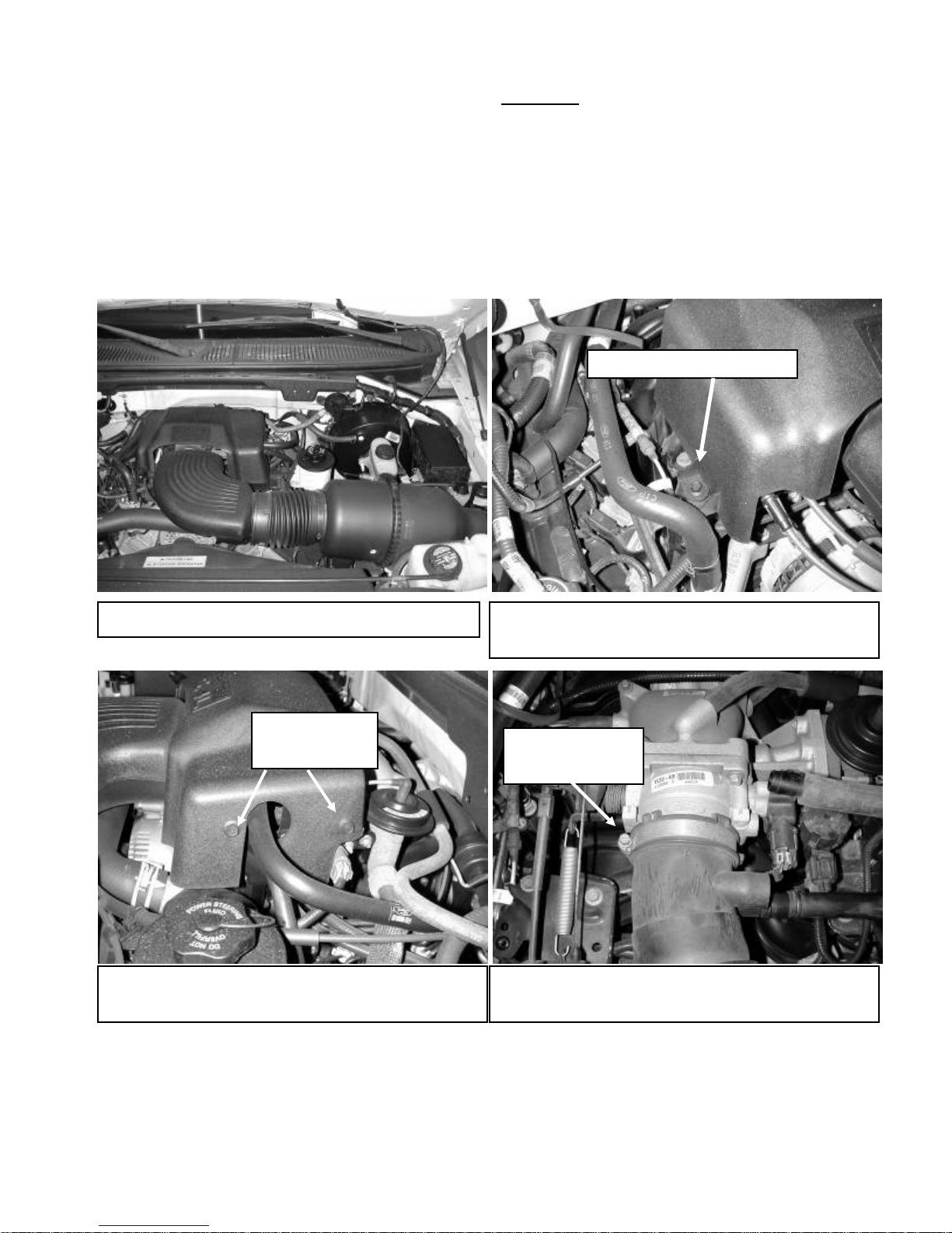
a) Your stock intake system should look like this. b) Loosen and remove left bolt on the throttle body
cover.
Loosen and
remove bolts Loosen hose
clamp
d) With the throttle body cover off, loosen the hose
clamp at the throttle body.
c) Loosen and remove the two remaining bolts on
the driver side of the throttle body cover.

4
h) Unclasp latch for the air filter and MAF sensor.
g) Loosen hose clamp and remove inlet tubing up to
the throttle body.
e) Remove IAC and Crank case breather tubes from
the upper air inlet tube.
Unlock
Remove inlet tubing.
Loosen hose
clamp.
Remove both breather tubes. Remove IAT sensor.
f) Remove the IAT sensor from the air inlet tube.
i) Unlock the MAF sensor from its
housing.

MAF sensor connector
MAF sensor housin
g
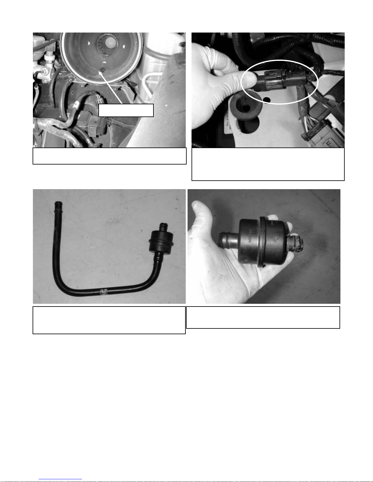
j) With the assembly open locate the MAF sensor. Disconnect the MAF sensor and
pull the connector from the housing. The MAF sensor housing will not be reused.
l) Remove air filter.
k) The stock MAF sensor assembly should look like
this.
5
n) Remove the clip for the MAF sensor harness
connector that holds it to the mounting surface. Make
sure this mounting surface is flat for the heat shield
installation.
m) Remove the air filter housing.
Air filter housing
Mounting Surface
p) Check valve removed.
o) Remove this portion of the IAC breather tube from
the vehicle. The tube will be removed and the check
valve will be reused.
6

3) Installation of the AEM Brute Force Intake System.
a) When installing the BFI System, DO NOT completely tighten the hose clamps or mounting tab
hardware until instructed to do so later in these instructions.
Attach coupler
c) Insert grommet into upper inlet pipe.
b) Attach reducer coupler and hose clamp to the
throttle body.
Insert u
pp
er inlet
p
i
p
e.
Loosen all three bolts.
e) Loosen all three bolts to the power steering
reservoir.
d) Insert upper inlet pipe. Secure with hose clamp.
7
Loosen and remove.
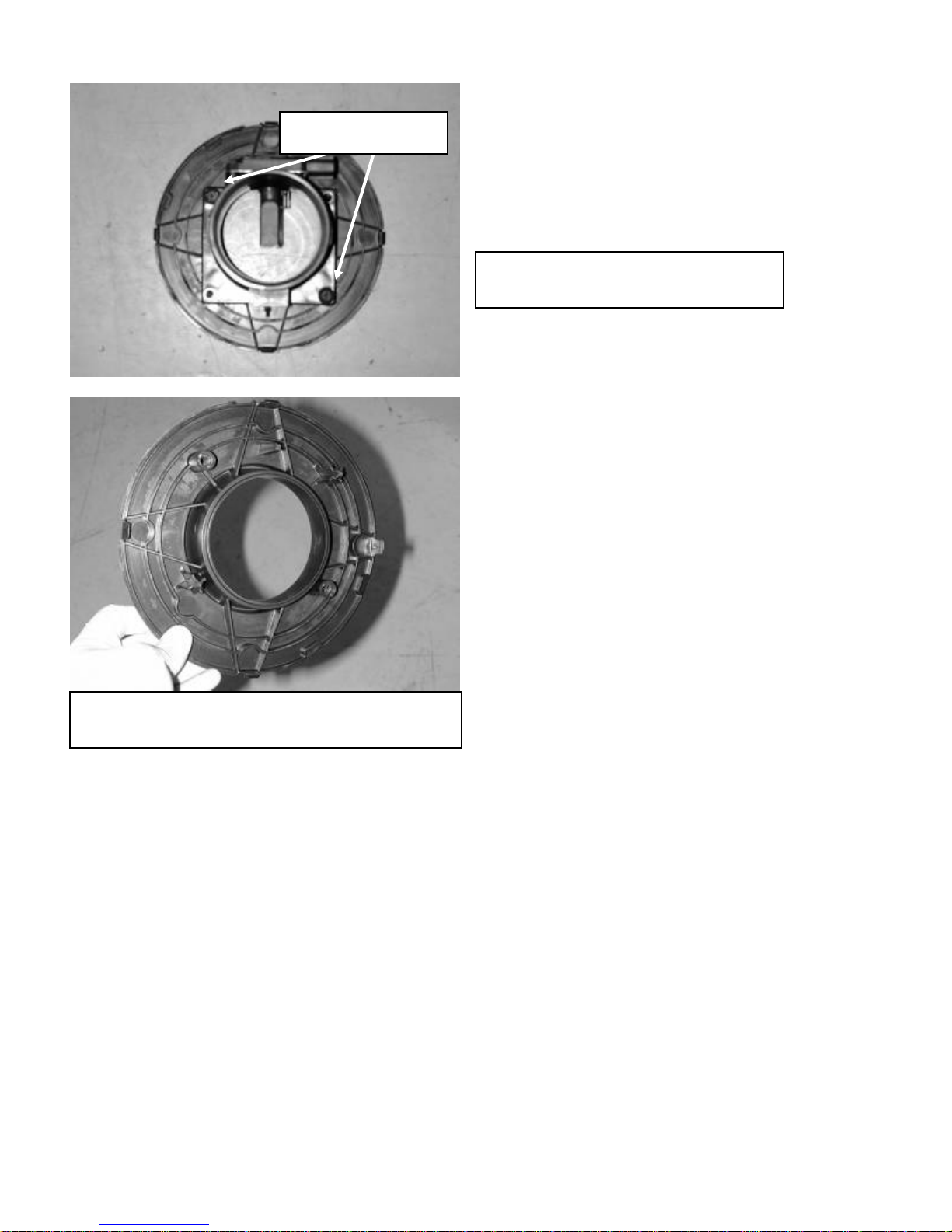
f) Loosen and remove the two bolts on
the stock MAF assembly.
g) This part of the stock MAF sensor assembly will
not be reused.
8
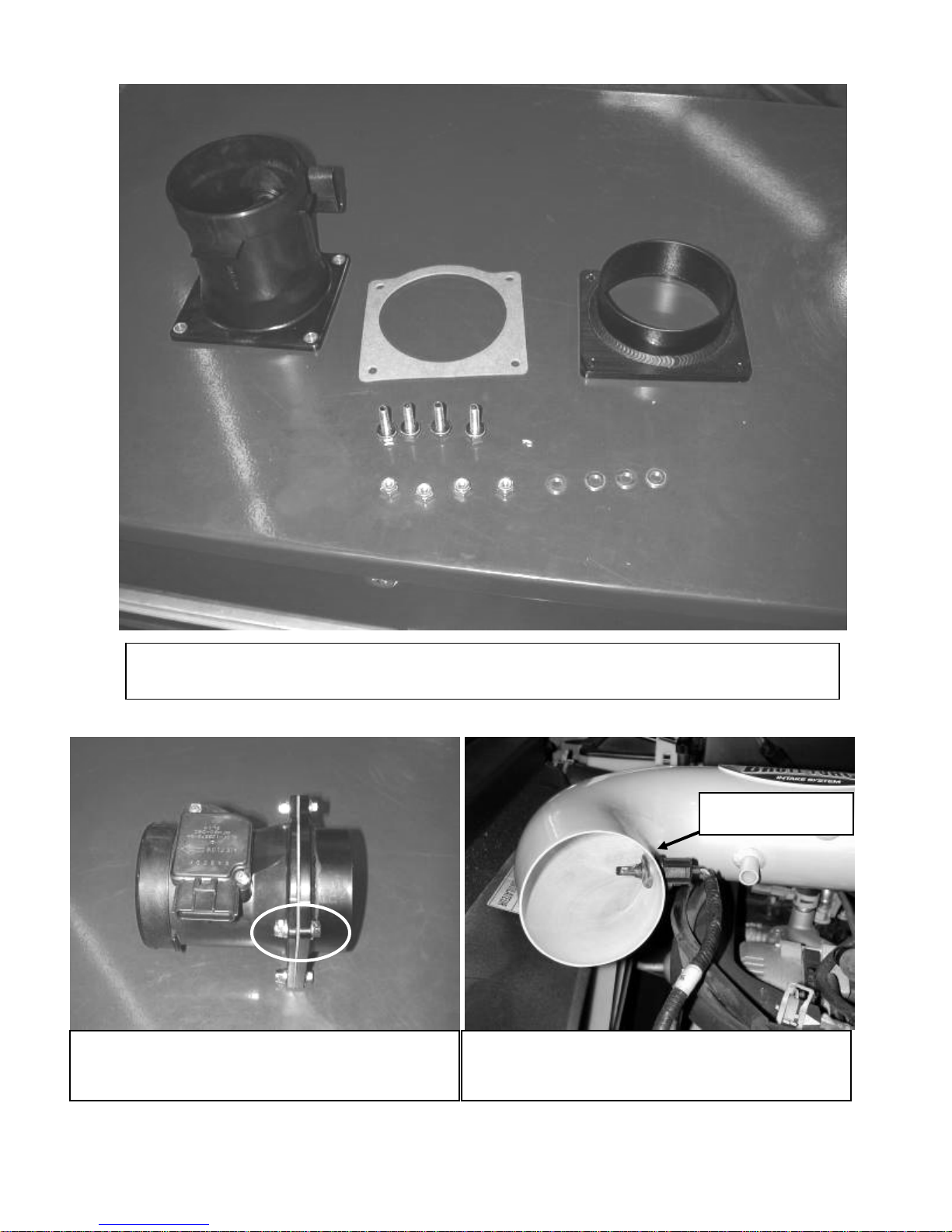
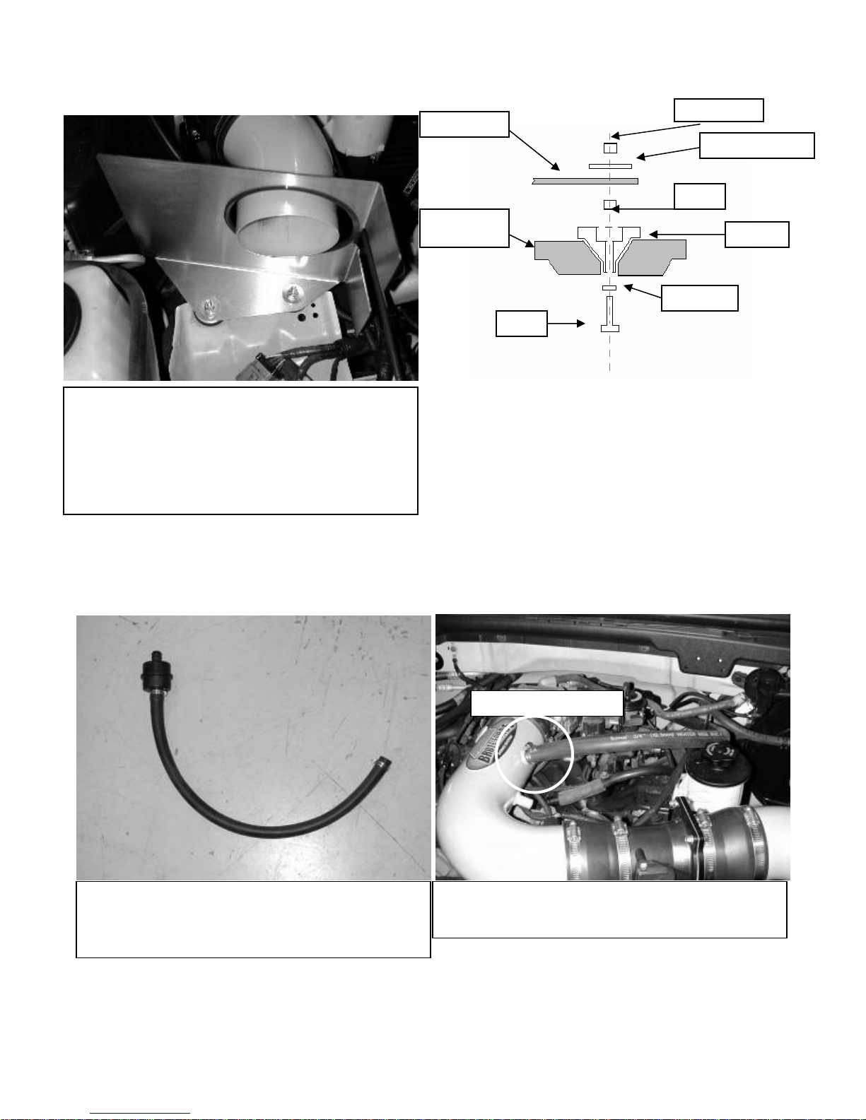
h) The new BFS MAF sensor assembly will contain the above hardware. 1 MAF sensor, 1 Gasket, 4
M6x20 bolts, 4 nylok nuts, 4 M6 washers and the MAF sensor adapter.
Insert IAT sensor
i) The assembly should look like the above photo.
The order is nylok nut, washer, MAF sensor, gasket,
MAF sensor adapter, and bolt head.
j) Insert IAT sensor into grommet in the upper inlet
pipe.
9

l) Attach MAF assembly to the upper inlet pipe, the
flow arrow on the MAF sensor should be pointing to
the upper inlet pipe.
k) Attach reducer couplers and 3 hose clamps to the
MAF assembly. The flow arrow is pointed to the right
on the MAF sensor.
m) Insert the second inlet pipe. The bracket will
be inserted underneath the tab on the power
steering reservoir.
10
n) This is the hardware that attaches the heat
shield to the mounting surface. 1 ¼-20 bolt, ¼”
washer, heat shield spacer, and ¼-20 nut.
o) Insert the bolt and washer from underneath the
rubber grommet. Insert the heat shield spacer and
secure with the nut.
Nylok Nut
Heat Shield Fender Washe
r
Nut
Rubber
Mount S
p
ace
r
Washe
r
Bolt
A
ttach breather hose
p) Attach rubber edge trim as shown. Secure heat
shield with washer and nylok nut. Make sure the heat
shield clears the A/C line on the left and the cruise
control on the right. Note: Heat shield may differ from
one pictured, some require the removal of two bolts
on the cruse control module and the installation of
the Heat Shield zip-tie to secure throttle cable.
r) Secure breather hose for the IAC to the upper
nipple on the pipe.
q) Attach breather hose for the IAC and secure to
check valve. If your check valve is located in
front, next to the throttlebody you will need to
trim the hose to approximately 6”.
11
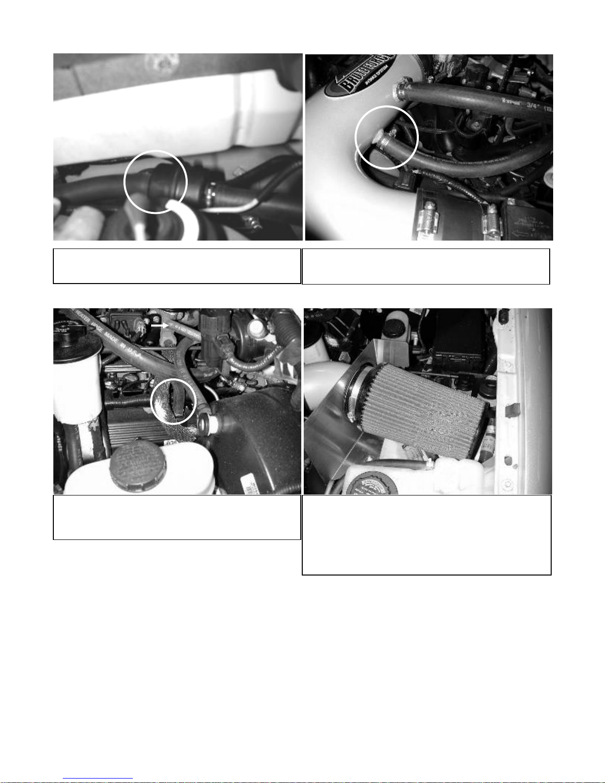
t) Attach crank case breather tube and secure to
nipple on upper inlet pipe.
s) Attach the check valve back to its original spot
near the firewall.
u) Attach the other end of the crank case breather
tube to the nipple on the crank case and secure. v) Attach filter the inlet pipe. Check for clearance.
Secure filter. Note: some models will have the
coolant reservoir behind the filter. These models
will require the coolant hose be extended using
the supplied barb fitting and 3/8” hose. Use the
¾” hose clamps to secure.
12
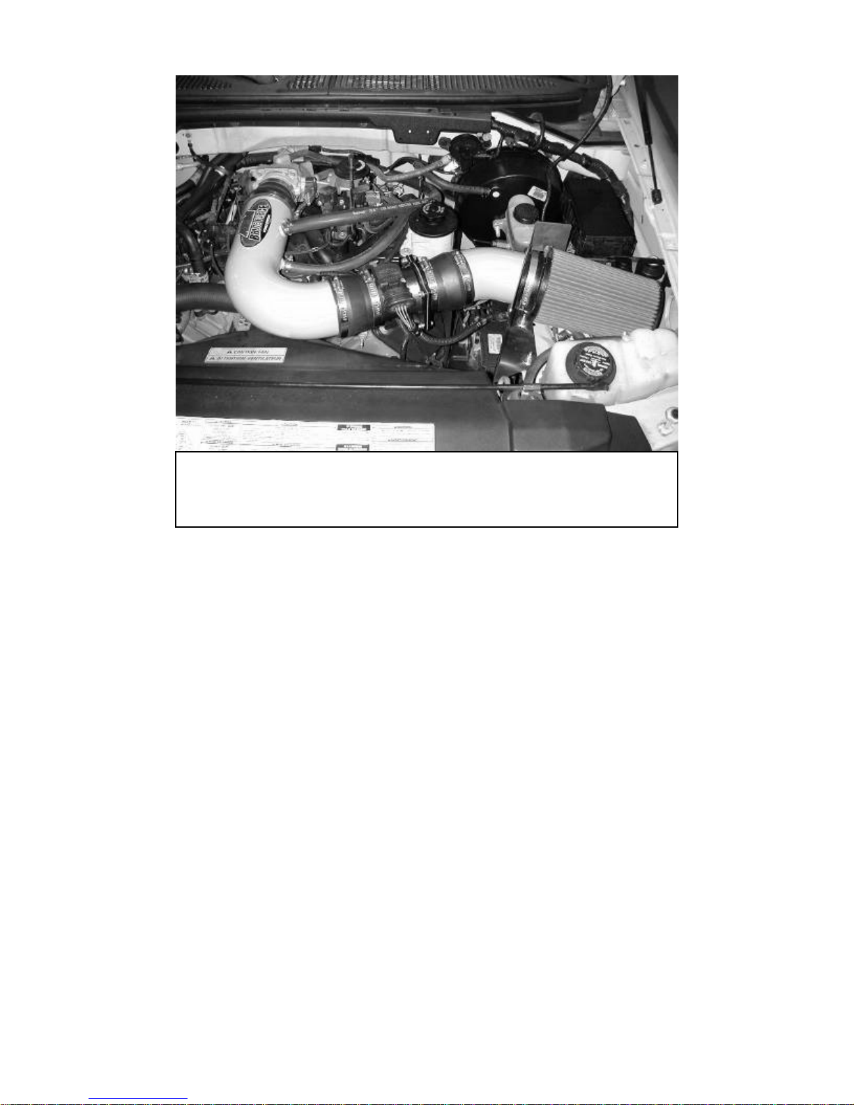
w) Your Brute Force System should look like this. Note the MAF sensor’s
position. The sensor should be facing the hood. Failure to do so may cause
a rough or low idle and poor drivability. Finally, plug the wire harness
back into the MAF sensor.
x) Position the inlet pipes for best fitment. Be sure that the pipes or any other
components do not contact any part of the vehicle or heat shield. Tighten all bolts and hose
clamps. Check hood clearance.
4) Re-Assemble the vehicle.
a. Inspect the engine bay for any loose tools and check that all fasteners that were moved or
removed are properly tight.
b. Start engine and perform a final inspection before driving the vehicle.
For technical inquiries e-mail us at [email protected]
13
Other AEM Other manuals


