aeolus UC-1801 User manual
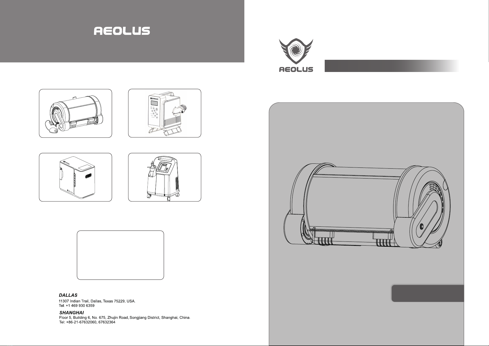
Distributor Contacts
UC-1803
KO2-10FKO2-2F
UC-1801
PET ICU.INCUBATOR
WMS-1501
User Manual
Professional Vet Equipments Supplier

Overview
Summary of Important Notes
Product Use
Cleaning and Maintenance
01
02
02
02
05
06
09
14
17
The Instruction Manual is used for AEOLUS UC-1801ICU.INCUBATOR (Pet ICU/Young Pet Incubator)
designed by AEOLUS International.
Installation, use, cleaning, maintenance and repair of the ICU, as well as principles and functions of the
product, caution and warnings, common fault analysis and troubleshooting and after-sales services etc. are
all in the Overview. Users should operate the product in accordance with requirements as stated in the
Instruction Manual. The warranty does not apply in cases where the product fails due to incorrect operation
or improper maintenance by non-professionals. All staff use the equipment shall read the Instruction Manual
carefully before turning on the equipment. If you have difficulty in understanding the Manual, please contact
a local AEOLUS product distributor or the company for more detailed information.
AEOLUS UC-1801-ICU.INCUBATOR (Pet ICU/Young Pet Incubator) is a newly developed pet ICU and
young pet incubator developed to serve an enormous need and fill a vacancy in the domestic pet care
industry. This moderately sized piece of pet medical equipment will easily fit into most veterinarians’ practic-
es and pet hospitals. Its characteristics and compact structural design functions perfectly server its purpose.
The mechanism adopts "dual duct and double circulation convective thermal regulation" to create an
excellent and bacteria-free therapeutic environment and young pet incubation environment similar to that
provided pet parent (accompanied by purified air and proper temperature and humidity control).
In many countries, our Company is the first to introduce computer technology and auxiliary medical devices
for pets in the area of ICU control systems. This allows for more accurate temperature control of ICU, and
brings greater convenience for clinical use. The machine is equipped with an intelligent alarm device for five
faults sensor, extreme temperature, excessive moisture, indoor carbon dioxide concentration, lack-of-water
in the tank and power supply Interruption). This alarm system is tested and proven to be safe and reliable.
Furthermore, it is equipped with a unique cabinet structure and double-layer thermostat cover, which can
prevent loss of heat and radiant heat when nursing the pets. In addition, a temperature and humidity display
device is provided, measuring current temperature with the set temperature clearly visible. The heating
control adopts dual duct and double circulation convection heating technology. This prevents rapid change
in temperature minimizing the shock that can be caused. It ensures that temperature of the ICU can rise
evenly and gently. The Thermostat System adopts PID control technology, which can solve the problem of
inertia temperature error comprehensively, thus the temperature control is more accurate and more energy
efficient.
AEOLUS UC-1801 ICU.INCUBATOR is a fully integrated pet ICU and incubator.
AEOLUS UC-1801 ICU.INCUBATOR accurately controls temperature and humidity. It is the only domestic
product with balanced heating and stable temperature and humidity (used in ICU).
AEOLUS UC-1801 ICU.INCUBATOR provides a bacteria-free therapeutic environment, which can efficient-
ly kill all harmful bacteria and viruses.
AEOLUS UC-1801 ICU.INCUBATOR incorporates integrated adjutant therapeutic functions, not just the
functions of an ICU.
AEOLUS UC-1801 ICU.INCUBATOR provides air purification with medical effects, rather than concept
speculation
AEOLUS UC-1801 ICU.INCUBATOR accurately monitors the medial environment, which safeguards the
pets’ lives.
AEOLUS UC-1801 ICU.INCUBATOR is an Earth friendly product; saves energy and protects the environ-
ment, which can effectively savings 35% of energy (when compared to other pet care products).
AEOLUS UC-1801 ICU.INCUBATOR especially provides the creation of a bacteria-free environment. The
dual duct and double circulation convection heating technology and the PID thermostat control technology
are pioneering, which ensure the reliability, safety and practicality of the machine.
Overview
CONTENTS
01

1. Installation Checklist of the Whole Machine:
2. Installation of Humidifier Vessel
3. Nebulizer Parts Installation
Summary of Important Notes
Product Use
Product Installation
1. Please read the Instruction Manual carefully before using the machine. Nurses (and other pet care workers) should
be trained to operate the machine under the guidance of qualified medical care personnel who are familiar with the
functions of ICU/Young Pet Incubator and understand the risks and advantages of the machine.
2. Please count the parts and spare parts when unpacking, and read the Instruction Manual carefully.
3. The equipment shall be placed in a clean place with limited changes in temperature and humidity, protected from
direct sunlight and away from heat radiation.
4. To ensure the proper operation of the Pet ICU, please DO NOT fill the bottle with distilled water or purified water.
5. After the machine is turned on, please preset the temperature value, and warm it up for 3-5 minutes before use.
6. Please do not load weight onto the machine, and the maximum load capacity of the machine housing is 1-2
kilograms (2.2 to 4.45lbs).
7. Unsanitary cleaning materials will cause the generation of carbon dioxide, and thus increase the carbon dioxide
concentration in the pet ICU. The equipment should be inspected and cleaned. And the air purifying materials shall be
replaced in a timely manner and on a regular schedule.
8. The machine is equipped with an intelligent alarm system sensor for five faults; extreme temperature, excessive
moisture, indoor carbon dioxide concentration, lack-of-water in the tank and power supply Interruption. This alarm
system is tested and proven to be safe and reliable. If the machine fails, please inspect the systems immediately to
find out reasons and eliminate the faults. If the faults cannot be eliminated in a short time, please stop medical
treatment or care for pets, and ask for professionals or personnel from the AEOLUS Company to repair the machine.
9. Allow for the machine to have proper ventilation. Do not block the air outlet and return air inlet.
10. After being powered on, if the machine is not used, in order to ensure safety and energy-saving, please turn the
switch to off position and allow for sufficient power down before turning the switch back to on position.
11. Do not use alcohol or other organic solvents to wipe the thermostat cover of the tank. Keep it moisture free.
1. Provides bacteria free and thermostatic incubation cocoon for young pets.
2. Allows for body temperature recovery, fluid infusion, atomization treatment, incubation, health improving
and comfortable, stable stay in the hospital (for observation for sick, dying and weak pets).
Built-in humidifier bottle: some parts of medical atomizer and the tank are separately packed. Please pay
attention not to damage or miss any parts or spare parts when unpacking.
AEOLUS UC-1801 ICU.INCUBATOR cabinet -----------------------------------------------------------------------1
Built-in humidifier bottle ---------------------------------------------------------------------------------------------------2
Plastic neck of the humidifier bottle ------------------------------------------------------------------------------------3
Main body of the medical atomizer -------------------------------------------------------------------------------------4
Nozzle of the medical atomizer ------------------------------------------------------------------------------------------5
Medicine cup of the medial atomizer -----------------------------------------------------------------------------------6
Water tank of the medical atomizer -------------------------------------------------------------------------------------7
The 850EA Nebulizer is installed at the left side of AEOLUS UC-1801-ICU.INCUBATOR, could be
exposed once the protection grid removed, as showed in figure 9.1.1.
Five parts compose the 850EA nebulizer, including nozzle, cup lid, nebulizer panel, medicine cup and air
pipe.
These 5 parts need to be assembled in the order indicated in figure 9.1.2 and fixed by the C clip (f in
figure 9.1.2) before nebulizer switched on.
Animal-specific
medical nebulizer
Nebulizer grid tray
Fig.9.1.1
Fig.4.2.1 Fig.4.2.2
Fig.9.1.2
escripon
OM I
Quanty
nole
a
1
nebulier clip
f
1
escripon
OM I
Quanty
cup lid
b
1
air pipe
e
1
escripon
OM I
Quanty
nebulier panel
c
1
medicine cup
d
1
As shown in Figure 4.2.1, the Humidifier Vessel is installed in the right control chamber of the AEOLUS
UC-1801 ICU.INCUBATOR. As shown in Figure 4.2.2, open the outlet cover, take out the built-in Water
Vessel, fill the built-in Water Vessel with water, as shown In Figure 4.2.2. And then put back the vessel
and place the cover in the proper position.
Notes:
a) The Humidifier and Water Level Sensor should be placed securely onto the vessel to prevent the
spill of water.
b) Do not fill the vessel with purified or distilled water, which may cause the malfunction of the Water
Level Control of the water tank and may eventually cause water to spill or leak.
c) The water level should not be above the Highest Level Line (HLV).
d) The purpose of the water purification filter material is to remove hard water scale and improve the
water quality. The validity period of each placement is 10-12 months. Colorless, tasteless and non-tox-
ic, the filter material meets the National Sanitary Standard for Drinking Water& GB1499- 1988 and can
effectively improve water quality.
Outlet Cover
Sensor
of Vessel
Water Vessel
02 03
Soft gasket of the medical atomizer -------------------------------------------------------------------------------------8
Power line of AEOLUS UC-1801ICU.INCUBATOR --------------------------------------------------------------- --9
Stainless steel tray of AEOLUS UC-1801ICU.INCUBATOR -----------------------------------------------------10

Product Principles and Functions
The patented Energy Saving Low Noise Compressor (less than 25 decibels) generates high speed air jet
from filtered clean air (by anti-bacterial cotton), the air stream disperses the medicine solution from liquid
cup into tiny particles and form medicine aerosol. The average size of droplet could reach 2.5μm minus
which could reach deep respiratory system like alveolus and fine bronchus. The medicine is nebulized
evenly, no diluted needed, so there is no residues left almost and could achieve very high medicine
utilization rate. This device is preciously made medical equipment with very low faulty rate and very good
durability, could serve for 1000 -1500 hours as minimum lifespan.
Usage Warning:
a) The treatment process should not exceed 20 minutes for every nebulizing, misuse would possibly cause
Pulmonary edema or water poisoning.
b) To prevent superinfection, please pay close attention to the sterilization of nebulizer, ambient air and all
the related equipment, also disinfect animal mouth, nose and throat.
Mechanism of action
Animal respiratory system is an open system, where alveolus is the main air-exchanging place. The object
sprayed out of the nebulizer is mainly the mixture of oxygen and medicine – oxygen-medicine aerosol. This
kind of aerosol could improve oxygen metabolism and anoxic metabolism significantly; increase the oxygen
reserve in organisms. The cavitation effect of compressed air could disperse the liquid medicine into gas
phase and turn the liquid into fog form. The suspended particles will get deep into animal respiratory system
and treat the focus of infection directly. The feature of air compressing nebulization technique is generating
Big Fog Volume Fog with Ultra Small Particle Size (0.5 -5μm); the even fog could go very deep into dendritic
bronchus and the particles could settle down in deep respiratory system, achieves painless cure effect. It is
a good helper to improve curative effect and accelerate recovery process.
Tips:
a) The smaller the particles are, the better curative effect the nebulization could achieve.
b) Normally the fog with bigger particles generated from traditional ultrasonic nebulizer would be easier to
be observed, as the fog seems to be thicker.
c) The international of human medical nebulizer is the particles in fog need to be smaller than 5μm.
850EA Air Compressor Nebulizer uses high pressure gas jet knockout the medicine solution into tiny
particles and carry them into deep respiratory system. The size of droplet will affect the settlement site of
medical fog.
roplet Sie
Selement Site
15m
endric roncusFine roncuslveolus
520m
roncus
2040m
Upper espiratory Tract mainlyNoseTroatetc
Fig.9.2.1 Fig.9.2.2
Fig.9.2.4 Fig.9.2.5
Fig.9.2.3
The air circulation system as shown in Figure 5.1.1 is
driven by the circulating air of AEOLUS UC-1801
ICU.INCUBATOR (Pet ICU/Young Pet Incubator). After
being filtered by the purifier, the air from the outside
enters into the ICU, and "dual duct and double
circulation convection heating technology" is adopted to
create an excellent and bacteria-free ICU therapeutic
environment and young pet incubation environment. It
provides clean air and proper temperature and humidity.
1) Power supply voltage: 220V±10%/50Hz±2%
2) Input power: ≤400VA
3) Ambient temperature: 10°C ~ 35°C
4) Temperature control range
Cabinet temperature: 15°C ~ 38°C (can be up to 39°C by special operations)
5) Temperature fluctuation: ≤0.8°C
6) Average temperature of monitoring chamber: ≤1.0°C
7) Cabinet temperature control accuracy: ≤±0.5°C
8) Temperature rise time: 5min ~ 20min
9) Noises in monitoring room: ≤30dB
10) Whole machine earth leakage current: ≤0.5 mA (normal state) ≤1 mA (single fault state)
11) Withstand voltage: 1500V/50Hz, lasted one minute without breakdown and flashover.
12) Ambient conditions: ①Transportation and storage: a. Ambient temperature: -10°C~40°C
b. Relative humidity: ≤95%
② Operating conditions: a. Ambient temperature: 18°C ~ 30°C
b. Relative humidity: 40% ~65%
Operation Instructions:
850EA nebulizer is easy to operate, please follow the simple steps as follows.
1. As showed in Figure 9.2.1, open the nebulizer grid, remove the nebulizer cup from the C clip. If the
operator is skilled at this process, he/she could also follow the second step without taking the cup off.
2. Figure 9.2.2, screw off the cup lid and nozzle; pour medicine liquid into the nebulizer cup.
3. Figure 9.2.3, screw on the cup lid and nozzle, and put them back to the left side nebulizer chamber.
4. Figure 9.2.4, Press Nebulize button on control panel to switch on nebulization, the medical fog will be
sprayed through grid and get into the ICU chamber. There are two stages of nebulization treatment timing,
in which the basic time is 10 minutes. Once the nebulization process started, it is 10 minutes countdown
automatically; pressing the "-" button on the nebulize adjustment button will turn it into 20 minutes mode,
pressing the "+" will turn back to 10 minutes mode. Pressing Nebulize button again on the main control
panel when the nebulizing process is running will switch the nebulizer off.
Tips:
a) There is hissing noise when nebulization starts, that’s generated from the high speed air flow. The
patented low noise air compressing technology ensures no vibration and no electronic noise when nebulizer
runs. The noise is much lower than normal level of most air compressor nebulizer, which is around 85
decibels normally.
b) When nebulization is ON, the ventilation fans will be turned off to ensure good nebulizing effects, and
humidity and temperature control will be turned off too. The humidity alarm will Not be triggered in nebuliza-
tion mode, which will reset in 3 minutes after nebulization function turned off.
c) The nebulizer panel should be placed at right position as showed in this picture. See Figure 9.2.5
04 05
1. Mechanism of AEOLUS UC-1801 ICU.INCUBATOR
2. Main Technical Indicators

1. Accurate Temperature Control---Being Equal Everywhere
Functions of the Product
Without being heated, high-frequency oscillation technology is adopted to product mist.Compared to
heating atomization, it can save 90% of energy. During atomization, large amounts of negative ions are
released, and have static electricity reaction with smoke and dust in the air, and cause precipitation.
According to the data released by World Health Organization, negative-ion is called “air vitamin”, and an
animal needs about 10 billion ecological negative-Ions every day, while our living environment can only
provide about 0.1-2 billion ones; when the negative-ion concentration in the air is up to 400 ones/cm³, it
can satisfy our basic needs for survival; when the negative-ion concentration in the air is up to 1000-2000
ones/cm³, it can satisfy our basic needs of health; when the negative-ion concentration in the air is up to
5000-10,000 ones/cm³, it can Improve our immunity and antibacterial ability; and when the negative-ion
concentration in the air is up to 300,000-500,000 ones/cm³, it can Improve our natural healing ability, and
many diseases can be healed without medication. Negative-ion plays a significant role in improving the air
quality of treatment room and improving and maintaining the health of animals.
AEOLUS UC-1801ICU.INCUBATOR provides a high concentration of negative-ion generator, and the
following is the negative-ion test report:
Heating control adopts dual duct and double circulation convection heating technology to allow tempera-
ture rising quickly, and temperature shock is small to ensure the temperature ofthe ICU can raise evenly.
Refrigeration control adopts special pet medical refrigerator matching system, which is characterized by
fast cooling and obvious effect. Furthermore, dual duct ice can be used for auxiliary cooling. (Note:
medical refrigerator is optional)
Thermostat system adopts PID control technology, which can solve the problem of inertia temperature
error comprehensively, thus the temperature control is more accurate and more energy-efficient.
The humidifier water tank adopts built-in technology, and the integrated design of the product enables the
operation more reasonable.
It is easier to clean the scale in the humidifier, just put a few drops of vinegar into the tank, and then the
scale can be cleaned.
Silent humidification, even humidification and more accurate control.
Equipped with automatic water cut-off protection function. When the water supply is cut off, there is still
certain amount of water left in the tank; thus, it is impossible for idle burning, which is safer to use.
The above test report shows that: the nearby negative-ion concentration of AEOLUS UC-1801- ICU.INCBA-
TOR is up to 6 million ones/cm3 standard, which has reached the medical-level Negative-ion emission
standard. It is truly air purifying, and is effectively helpful for the rehabilitation and recovery of pets.
06 07
2. Accurate Humidly Control---Healthy and Balanced
3. Negative-ion Generation---Truly Auxiliary Medical Effect
UC-1801
Test equipment: KEC-990 air ion concentration tester, HG3830 high voltage test bench
Drop test
II Principle of Operation
Low-temperature
characteristics
High-temperature
characteristics
Humidity resistance
Storage temperature
Operating humidity range
Operating temperature range
-20°C~+70°C
40%~65%
-10°C~+60°C
MODEL NO Project Number Applicable specification and model
DC9-12V 1403140013
I Electrical Parameters
Input voltage/frequency DC12V
Output voltage At DC12V -0.5--4.5KVd.c.(-3.5KV DC ± 0.5KV DC )
Anion concentration At DC12V ≥6×10⁶ PCS/cm3 ±10%
Insulation resistance Power line external box ≥20M Ω (500V DC)
Dielectric streangth Power line external box AC 1800V
60HZ 5mA 3S No breakdown
Rated power
Input current
<1W
<80mA
The negative ion generator boosts low voltage to negative high voltage DC through the voltage booster
circuit. DC high voltage from the tip of carbon brush is used to produce high corona and lots of
high-speed electrons are released. Since electronics cannot exist in the air for a long time (the life of
existing electrons is n S level), they will be captured by oxygen molecules (O2) in the air immediately,
and then negative ions are formed; the working principle of which is the same as natural phenomenon
(negative ions are produced when there is thunder and lightning).
In case of no electricity, no abnormalities occur after being
placed for 72 hours at ambient temperature of +25°C and
relative humidity of 95%.
In case of no electricity, no abnormalities occur after being
placed for 72 hours at ambient temperature of +70°C
In case of no electricity, no abnormalities occur after being
placed for 72 hours at ambient temperature of-20°C.
Starting at 100cm (39.37”) from the ground, free fall onto the
board, it will still function properly.

Product Operation Instructions
A UVC ultraviolet ray is the one that truly has germicidal effect, and C ultraviolet of which is easily absorbed
by DNA of organisms, especially, ultraviolet ray of 253.7nm is the best. UV sterilizer is a purely physical
method of disinfection, which is characterized by simple and convenient operation, high efficiency, no
secondary pollution, easy for management and automation etc.
AEOLUS UC-1801- ICU.INCBATOR uses ultraviolet sterilizer, which is characterized by strong radiation
intensity, high stability and high transmittance to quartz glass tube. The transmittance is of ≥87% and the
radiation intensity is at 253.7-254μm and remains stable. Furthermore, high brightness mirror sterilization
reaction chamber design is adopted. Compared with similar products from abroad, the sterilization strength
increases by 18%-27%.
---- Generally, the bactericidal action of ultraviolet ray on bacteria and viruses can achieve sterilization rate
of 99%-99.9% in one to two seconds.
---- The broad-spectrum of ultraviolet sterilization is the highest, and it can efficiently kill almost all bacteria
and viruses.
---- The ultraviolet sterilizer has no secondary pollution. No chemicals will be added in ultraviolet steriliza-
tion, thus, water and its surrounding environment will not be polluted secondly. Furthermore, it will not
change any ingredients in the water.
---- The operation of ultraviolet sterilizer is safe and reliable: traditional disinfection technologies such as
chloride or ozone, the disinfectants themselves are highly toxic and flammable substances, while there is
no such potential safety hazard in ultraviolet sterilization system.
AEOLUS UC-1801- ICU.INCBATOR is equipped with silent medical atomization function, and biomedical
engineering research shows: when the atomized particles are about 10 microns, medicines can only
deposit in the mouth and throat, when the atomized particles are about 3-6 microns, can enter into the
bronchus, and when the atomized particles are less than 2 microns, medicines can enter into the finest
bronchus and alveoli. The atomized particles of medicine produced by AEOLUS UC-1801- ICU.INCBATOR
are 0.5-4 microns. Meanwhile, intelligent control quantity of atomization is provided for your selection, and
the maximum atomizing volume is up to 0.5ml/min. The atomization in the ICU is even, and the inhalation
effect of atomized medicines is obvious. The medical built-in atomizer is characterized by low noise, which
complies with pet ICU noise standard.
AEOLUS UC-1801- ICU.INCBATOR can also provide an external air compressor atomizer you are your
selection according to users’ preferences and usage, which offers greater choice space.
An increase in carbon dioxide concentration is accompanied by a decrease in oxygen concentration. Being
anoxic under high concentration of carbon dioxide for a long time will cause pulmonary edema, cerebral
edema, metabolic acidosis, electrolyte imbalance, shock, hypoxic encephalopathy, etc. When the carbon
dioxide concentration reaches 1000PPM above, it will cause dizziness, drowsiness and reduced resistance
to pets; when the carbon dioxide concentration reaches 2000-5000PPM, it will cause mild nausea, poor
breathing, rapid heartbeat and electrolyte imbalance to pets, and seriously affect the health of pets and their
postoperative rehabilitation; and when the carbon dioxide concentration is over 5000PPM, it will cause
severe hypoxia, coma and even death.
set value for three minutes, It will trigger the alarm system and start the intelligent ventilation system at the
same time, being ventilated with the outside air and thus improve the air quality of ICU, which becomes the
most important life defense line for pets.
The ICU of AEOLUS UC-1801- ICU.INCBATOR is equipped with a precise carbon dioxide concentration
monitor, which can monitor changes in carbon dioxide concentration in the ICU. When being hypoxic state
that concentration exceeds the standard value (exceeds the set value), and cannot be reduced below the
AEOLUS UC-1801- ICU.INCBATOR uses ten-level LED lights adjustment, which can simulate various
scenes similar to parent, forest oxygen bar, warm home, forest dawn and dusk twilight, etc., providing a
cozy and conformable therapeutic environment for pets.
AEOLUS UC-1801- ICU.INCBATOR adopts intelligent alarm system, and is equipped with corresponding
fault display function, such as extreme temperature and excessive moisture alarm, lack-of-water alarm and
main components fault warning lights.
AEOLUS UC-1801- ICU.INCBATOR is equipped with intelligent switch power keys, dividing into three
controls, i.e. power-on, start and power-off. This design is energy saving and safer to use.
All equipment components of AEOLUS UC-1801- ICU.INCBATOR adopt integrated design. All components
are integrated in a control frame, and completely separated from the control circuit. Only by disassembling
the control rack, the whole machine can be disassembled to clean various components, including fan,
medical devices, heat sink and filter etc. The operation is extremely convenient, easy for troubleshooting,
maintenance and equipment cleaning.
AEOLUS UC-1801- ICU.INCBATOR is equipped with two medical device import Interface channels, thus
external medical equipment (such as oxygen machine) can be connected into the ICU, meanwhile, the side
access port adopts medical valve importing design, being convenient for the importing of pets injection and
infusion needles and relative sealing and fixing.
a) One end of the power cord is plugged into the terminal
board at the bottom support of the right side of the
machine, and the other end into the socket of 220V/50Hz
with reliable grounding. See fig. 7.1.2.
b) The power switch is located at the batter brace of the
left side of the machine. See fig.7.1.2. It is the on/off
switch of AEOLUS UC-1801- ICU.INCBATOR. When it is
locked, all other keys are void; when it is unlocked, all
other keys are valid.
c) The lock indicator lamp is at the on/off switch. When it
is on, it means unlocked; when it is off, it means locked.
08 09
4. Sterilization Function ---- Free from Cross-contamination
7. ICU Illumination Function----Creating Comfortable Therapeutic Environment
8. Setting of Security Mechanism---- No Worries in Use
9. Human Oriented Structural Design ---- Reasonable Operation, Clean and Convenient
1. Start-up and Shutdown
5. Medical Atomization Treatment Function---- Making the Treatment More Convenient
6. Carbon Dioxide Concentration Monitoring Systems----A Defense Line to Guard Life
Figure 7.1.2
Power ON/OFF
Power Interface

Fahrenheit/centigrade can be switched and
displayed with a toggle key. The default tempera-
ture is shown in centigrade and in two-digit integer
and one decimal place after which is a letter
showing special indication at the time of setting the
temperature parameter. Switch the Fahrenheit/cen-
tigrade indicator lamp. When the indicator lamp
displays "C", it means centigrade; when it displays
"F", it means Fahrenheit. See fig. 7.2.1.
Humidity / CO2concentration display can be switched
with the humidity / CO2 concentration key. The default
is humidity display in two-digit integer and one
decimal place. CO2concentration is displayed in
four-digit integer. Switch the humidity / CO2
concentration indicator lamp. When the Indicator
lamp is "HU", it means humidity; when the indicator
lamp is "CO2", it means CO2 concentration. See fig.
7.3.1.
Key control: press "SET" key plus temperature "+/_" key at the same time to adjust the temperature set
point, and regulate it by ± 0.1 stepping. See fig. 7.4.1.The factory setting is the set point of 20°C. It can be
adjusted down to 15°C and up to 38°C;
Smart alarm function:
Alarm for beyond the maximum set point: the temperature and the upper dash are displayed alternately
every three seconds with alarm and flashing temperature indicator lamp.
Alarm for beyond the minimum set point: the tempera-
ture and the lower dash are displayed alternately every
three seconds with alarm and flashing temperature
Indicator lamp.
Damaged temperature sensor: flashing "ERR" display
and flashing temperature indicator lamp in the
temperature display.
Control program:
a) When the setting temperature is higher than the measured temperature, start the PID precise heating
system and left/right fans. When the measured temperature is higher than the setting temperature, stop
heating step by step.
b) When the measured temperature is higher than the setting temperature, start the PID precise cooling
system (need additionally purchased cooler) and the left fan to realize ventilation and air exchange inside
and outside. When the measured temperature is lower than the setting temperature, stop cooling step by
step and shut down fans after one-minute delay.
c) When there is no additionally connected cooler, try to place an ice tube inside the atomizing chamber or
at the sink as auxiliary cooling. The system will start the right fan and the left fan to realize ventilation and
cooling.
Indicator lamp control:
Heating---the temperature indicator lamp is red
Cooling---the temperature indicator lamp is blue
Delay---the temperature indicator lamp is yellow
Key control: press "SET" key plus humidity "+/-" key
at the same time to adjust the humidity set point, and
regulate it by±0.1 stepping. See fig. 7.4.1. The factory
setting is the humidity set point of 55%. It can be
adjusted down to 40% and up to 65%.
Alarm function:
a) Alarm for beyond the maximum set point: the
humidity and the upper dash are displayed alternate-
ly every three seconds with alarm and flashing
temperature indicator lamp.
b) Alarm for beyond the minimum set point: the
humidity and the lower dash are displayed alternately every three seconds with alarm and flashing tempera-
ture indicator lamp.
c) Damaged humidity sensor: flashing "ERR" display and flashing humidity indicator lamp in the humidity
display.
d) Humidifier water shortage alarm (the water level sensor of the humidifier is disconnected): in this case, if
the humidifier is started, the humidity Indicator lamp is off with water shortage alarm, and the humidity
display shows "LAC". Meanwhile, it starts the smart water shortage protection system.
Control program:
a) When the setting humidity is higher the measured humidity, start the humidifier and the right fan.
b) When the measured humidity reaches the setting humidity, stop humidifying.
c) When the measured humidity is higher than the setting humidity, start dehumidifying and the left fan;
reversely start the right fan for air exhaust as auxiliary dehumidifying. If an additionally purchased cooler is
connected, start the cooling function for dehumidifying.
Indicator lamp control:
The humidity indicator lamp is always on at the time of humidifying.
The humidity indicator lamp is flashing at the time of dehumidifying.
10 11
2. Temperature display
3. Humidity / CO2Concentration Display 5. Humidity Control Part
4. Temperature Control Part
Figure 7.5.1
Hold
Figure 7.4.1
Hold
Figure 7.3.1
Figure 7.2.1

Press "anion" key to switch it ON; and press it again
to switch it OFF.
When the anion is open, the anion indicator lamp is
on; when the anion is closed, the anion indicator
lamp is off. See fig. 7.6.1.
The atomizing volume of the medical atomizer has two grades, measuring by time and quantity. Press
"medical atomization" key to start the atomizing function (it is the higher grade with the atomizing volume of
0.375ml/min and the auto-timing of 10 minutes). Press "atomizing volume regulation" key to switch between
the higher grade and the lower grade of atomizing volume. The lower grade is 0.5ml/min with the auto-timing
of 20 minutes. When the medical atomization is started, the atomization indicator lamp is flashing quickly
(correspondent to the higher grade). Press "regulation" key to adjust it to the lower grade at the time of which
the indicator lamp is slowly flashing. Press "medical atomization" key again to stop atomization, and the
atomization indicator lamp is off.
a) Press "atomization" key to start the higher grade; press atomizing volume regulation key "+". To adjust it
to the lower grade, press atomizing volume regulation key "-". See fig. 7.7.1.
b) Press "atomization" key and get into the medical atomization status (higher grade) during which the
humidity display and control are shielded. The humidity display shows accumulated atomization time
counting (in seconds). After atomization and 10 sec delay, it automatically exits the atomization mode and
reverts to the humidity control mode.
c) During atomization, press "atomization" key to manually stop the atomization mode and revert to the
humidity control mode.
d) In the atomization mode, the humidity control is not effective. Therefore, when the humidity exceeds the
maximum set point, there is no alarm. If the humidity still exceeds the maximum set point in three minutes
after it exits (closes) the medical atomization mode, the alarm is started.
Atomizer water shortage alarm: when the water tank or the medicine cup of the atomizer is short of water,
stop atomization. The humidity display shows "ELAC" and the atomization lamp is off with water shortage
alarm. Press "atomization" key again to enter the "atomizer off" status and recover humidity display.
Press illumination adjustment key "+/-" to adjust
ten grades of illumination intensity. See fig. 7.9.1.
The highest is grade nine and the lowest is
closed. Under the Initial start-up status, it is
closed.
Key control: press "SET" key for five seconds to enter the parameters setting status. The humidity/CO2
display shows flashing digits of CO2concentration set value. When the indicator lamp "P" (CO2concentra-
tion) is flashing, it is able to adjust the set value of CO2concentration alarm. Now press humidity "+/-" key
to adjust CO2set value by±10 stepping. The default factory setting is the alarm set point of 800PPM which
can be adjusted down to 500PPM and up to 2000PPM. See fig. 7.10.1.
a) On: before starting the sterilization function, make sure that there is no pet in the ICU and the ICU door is
closed. Meanwhile, press "SET" key plus "sterilization" key to enter the disinfection mode. See fig. 7.8.1.
b) Operation: under this mode, all other function keys are void except "SET" key and "sterilization" key. Both
temperature display and humidity display show "DISI" (abbreviated disinfection); under the disinfection
mode, switch on the UV disinfection lamp. There is violet light inside the ICU (with weak acrid scent).
Meanwhile, start the left fan and the right fan to effect ventilation inside.
c) Off: press "SET" key plus "disinfection" key at the same time again to switch off the UV disinfection lamp,
the disinfection indication lamp and the left fan to exit the disinfection mode and recover the normal work
mode. At this time all function keys are valid except the disinfection key.
Note: when the ICU is under the normal work mode, it is invalid to press "disinfection" key individually.
12 13
6. Anion Control Part 8. Disinfection and Sterilization Control Part
9. Illumination Intensity Control
10. CO2Concentration Control
7. Medical Atomization Control
Figure 7.9.1
Figure 7.11.1
Figure 7.6.1
Figure 7.7.1 Figure 7.8.1
Hold press once message come out
Press once for start
Figure 7.10.1
Hold for 5 seconds
valne for co2alarm

Cleaning and Maintenance
Alarm and Processing Control: when the CO2concentration is higher than the set point and remains
constant for some time (to avoid false alarm for an abrupt increase of partial concentration), the CO2
Concentration Indicator Lamp is flashing with the alarm. Start both the left fan and the right fan to enhance
ventilation inside and outside. If the CO2concentration remains unchanged, open the ICU door to enhance
ventilation. When the CO2concentration is equal to or lower than the set point, switch off the CO2indicator
lamp and close the alarm. If fans are not needed when other functions are working the fans automatically
stop.
CO2Concentration Control: the default factory setting is 1000PPM-1000 in a million (0.10%). PPM=solute
mass/solution mass*1000000. Reference set point: the CO2concentration of 0.1% is harmful to animals;
the CO2concentration of 0.5% causes loss of breath and dizziness; the CO2concentration of 1% makes it
increasingly difficult for animals to breath, gradually fading to a fatal point.
CO2concentration in air: 0.030% -- 0.039% (oxygen concentration: 20.95%).
1. Disinfection & Sterilization: after incubation or caring of one pet finishes treatment and care, it is
suggested to disinfect and sterilize this machine. Do this once every week when not in use. It’s important
to maintain clean equipment.
2. Cleaning of the Humidifier (Old version): if the Humidifier falls to atomize, or the water spills out, take the
following measures:
a) Open the cover plate of the right Control Rack.
b) Remove the water tank of the humidifier. (Remember to disconnect the plug on the water tank
beforehand).
c) Brush off the mineral substance such as water scale or verdigris on the Water Level Sensors (the three
copper inserts on the inner surface of the water tank).
d) Place the water tank back, insert the connection plug, and secure the cover plate.
e) Brush off minerals on the inner water level sensor (the only slim metal column inside the humidifier
chamber) and the bottom vibrator (water scale) by sticking a brush into the atomizing inlet.
f) Cover the humidifier pipe.
g) Cover the inner cover plate. Make sure the rubber at the pipe outlet covers two feet at the bottom of the
cover plate. Installation tip: push the cover plate from top to bottom and then from outside to inside. Install
screws into the cover plate.
Press "SET" key to remove disengage alarms. See figure. 7.11.1.
14 15
11. Alarm Removal Key
Cleaning of the Humidifier (New version): if the Humidifier falls to atomize, or the water spills out,
take the following measures:
a) As shown In Figure 8.3.3-a, Open the cover plate of the Water Vessel of the humidifier (on the
control rack).
b) As shown In Figure 8.3.3-b remove Humidifier from the Water Vessel and as shown In Figure
8.3.3-c, remove Water Level Sensors.
c) Take out the Water Vessel of the humidifier as shown In Figure 8.3.3-d.
Sensor
of Vessel
Water Vessel
Figure 8.3.3-a
Figure 8.2.1-a Figure 8.2.1-b
Figure 8.2.3-c Figure 8.2.3-d
Figure 8.2.3-f Figure 8.2.3-g
Figure 8.3.3-b
Only for the products sold before 2018.
Only for the products sold before 2018.
Trouble-shooting
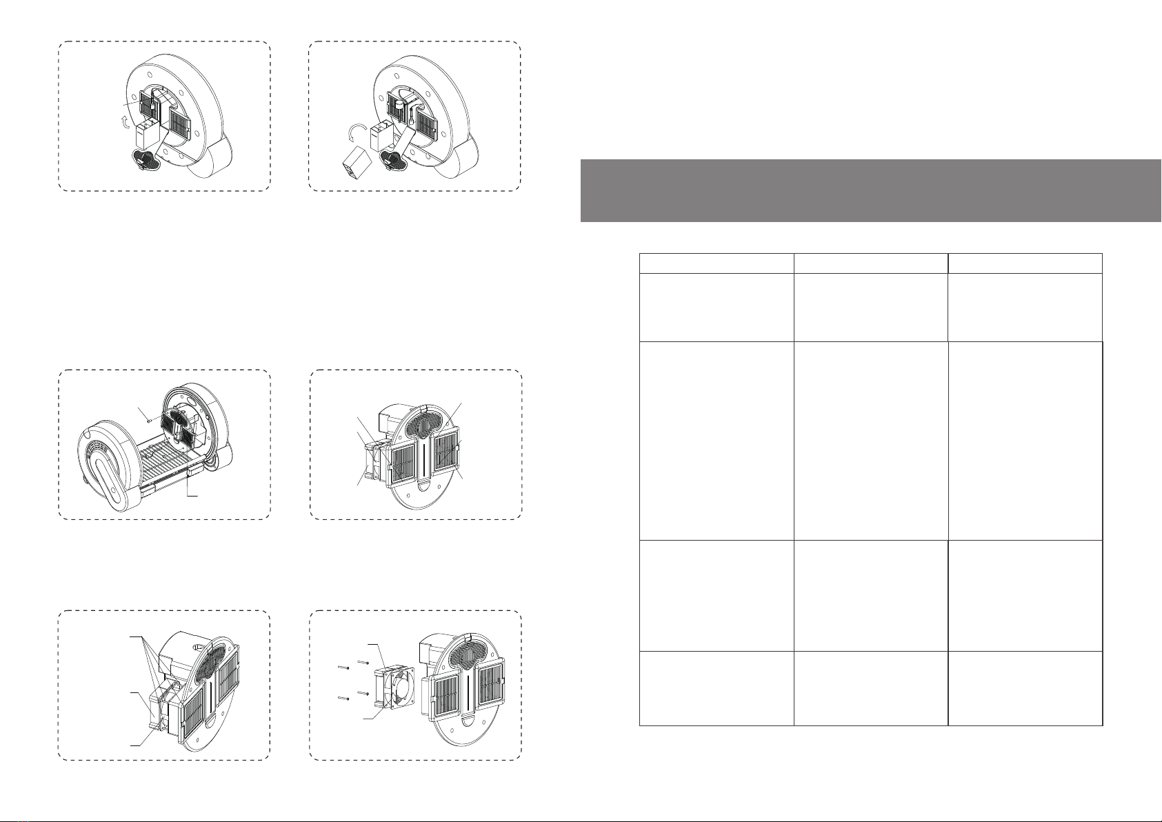
3. Complete Cleaning and Maintenance: remove and clean parts and assemblies periodically. Desired
results are achieved only by cleaning after removal.
Steps for Disassembling Components:
Remove four screws from the master control rack on the right to take down the right master control rack,
(remove the left master control rack in the same way). See figure. 8.3.1.
Remove power connection plugs on power cords on one side of the master control rack one by one. Note
that plugs have different colors for each electrical component.
Warning: do not remove control racks or electrical components from control racks immediately after shut
down; give it some time to cool down. The heaters in control racks reach high temperature. Remove control
racks or contact heaters after a 30 minutes respite after shutdown.
Remove and clean filters behind the square plastic section inside the chamber.
4. Cleaning
The ICU must be empty at the time of cleaning. Cleaning is feasible only after removal.
5. Maintenance
It is suggested to maintain the machine every two months during normal operation, which shall be carried
out in accordance with removal, installation and maintenance procedures above.
16 17
No atomizing form the
atomizer
1.Water shortage of the
water tank of the atomizer
2.Damaged ultrasnic chip of
the atomizer
3.Water scale in the tank of
the atomizer
Remaining solution not atomized
in the cup after atomization of the
medical atomizer
Atomizing time and volume
depend on concentration of
atomizing liquid
Repeat the atomization
operation procedure if not
completely atomized once
1.Add water into the water tank
until it is at the same level of
the cup bottom
2.Replace the ultrasonic chip
3.Gently scrub the inside of
the tank with lint
After the power switch is pressed,
there is no reaction or the power
indicator lamp is still off
Phenomenon
1.Bad power connection and
plug connection
2.Damaged switch
Cause analysis Solution
1. Check power connection
2.Replace the power switch
Little atomizing volume form the
medical atomizer
1.Too big atmizing particles of
solution causes little atomizing
volume
2.Solution contains syrup or
colloform
3.Tablets are used for
dissolution
4.Oily impurities on the surface
of solution
1.Too big particles are not
suitable for operation of this
atomizer
2.When solution contains syrup
or colloform,it requires with dry
filter paper
3.When tablets are used for
dissolution,dissolve sediments
to remove impurites first
4.Remove oily impurities on the
surface of solution with clean
tissue firstivvv
Sensor
Figure 8.3.3-c Figure 8.3.3-d
Remove four screws in the fan box and take out the whole heater. Clean the fan. Try not to remove heat sinks
from the fan, especially PTC heater bands that cannot be removed from heat sinks. See figure. 8.3.2.
Figure 8.3.1-b
Figure 8.3.1-a
Temperature
Humidity sensor
PTC Heater
Fan
Fan
PTC Heater
PTC Heater
screws of fan
Figure 8.3.2-a Figure 8.3.2-b

Dear user:
Thank you for using AEOLUS UC-1801-ICU.INCUBATORWe provide following services as
dictated in this warranty manual (and the invoice or other certificates of product purchase
according to "Law of the People’s Republic of China on Protection of Consumers' Rights and
Interests", as well as "Provisions on the Liability for the Repair, Replacement and Return of
Some Commodities" issued by the CSBTS and the Bureau of Finance.
1. One-year warranty for the whole machine.
2. Two-year warranty for key components (including medical atomizer, humidifier, anion
generator, ultrasonic sterilizer, fan, tank, door, master control panel, PTC heating chip).
3. Six-month warranty (from date of purchase) for replacement of key integral parts (including
medical atomizer, humidifier).
4. Warranty services are not provided under the following situations, (but paid repair services
are available for the life time of the equipment).
[A] No warranty card or any other certificate of product purchase presented
[B] Altered certificate of product purchase
[C] Damage caused by accident, abuse or misuse
[D] Repair privately without authorization of our company
[E] Products can be used after repair beyond the valid period of the three warrantees
5. The valid period of the three warrantees is from the date of product purchase, not including
time of repair and waiting for components if out of stock. During the valid period of three
warrantees, consumers can have products repaired, replaced or returned with invoice or
certificates of product purchase.
6. Within 15 days after purchase, consumers can return, replace or repair products if there is
any performance failure found.
7. Within 30 days after purchase, consumers can replace or repair products if there is any
performance failure found.
8. "Performance failure" indicates that products cannot meet safety and hygiene requirements
with unreasonable danger threatening safety of human body or properties; or products do not
have complete functional performance as required, or cannot meet explicitly expressed quality
conditions.
Advance replacement warranty service:
Your warranty service may involve advance replacement warranty service. If the hardware is
found to be defective after diagnosis, we will send replacement parts directly to you. After
receiving the replacement, you must return the defective part to us within the specified period
(normally five days). The transportation and insurance fees rising from return of the defective
part needs to be paid by you. If you cannot return the defective part, we will ask you for
replacement fees. We provide replacement services during normal working hours,
8:00 a.m. to 5: 00 p.m. Monday to Friday. The office time may be different according to local
time zones.
18 19
The humidity is not increased
after raising the set point of
humidity
Operational keys on the panel
do not work
Bad contact of panel plu-gins
Damaged panel keys
1.Install plug-ins properly
2.Replace the panel
No heating
1.Failed or damaged fan
2.Heater (heat sink) with bad
contact or damaged
3.ICU door opend
1.Check and replace fan
2.Replace heater band or heat
sink
3.Close ICU door
No cooling
1.No external cooler connected
2.Cooling pipe of the cooler not
connected to the tank
3.Signal line of the cooler not
connected to the machine
1.Connect it to an externally
purchased cooler
2.Check the cooling pipe
3.Plug the signal line into the
colling socket of the tank
Continuous alarm for CO2
concentration
1.Failed or damaged fan
2.Not enough instant
ventilation inside the chamber
3.Damaged CO2sensor
1.Check fans
2.Open the ICU door
3.Replace the CO2concentra-
tion sensor
1.Water shortage in the bottle
of the humidifier
2.Damaged chip of the
humidifier
3.Water scale in the metal
water level sensor inside the
humidifier tank
1.Add water into the bottle
2.Replace the humidifier
3.Remove water scale inside
according to the chapter of
"separate cleaning of the
humidifier", or try to dip some
vinegar into the water bottle of
the humidifier
AEOLUS UC-1801 ICU.INCUBATOR

Your warranty service may involve mail or courier. According to mail service provisions, you must
send defective hardware to an authorized maintenance facility via freight collect. We will repair and
return it to you.
Door-to-door pickup and return warranty service:
Your warranty service may involve door-to-door pickup and return services. The company or a
designated repair point will send technical employees to pick up defective hardware at your location
and send it back after repair. For such services, the company pays all maintenance, transportation
and insurance fees.
User Instructions:
For products beyond the warranty period, either the company sends service employees to pick up
or you can mail the defective part to the maintenance point. We provide our repair or replacement
services and parts (fees for maintenance after warranty) covering shipment costs, labor costs for
repair and component cost. Users can refuse to pay if maintainers cannot comply with unified
charging standards of the company.
Contact Customer Support and Service:
If information provided in these user instructions cannot solve your problem, contact the customer
support of AEOLUS Company at this website:
www.aeoluspet.com
Here you can:
1. Communicate with our technical employees online.
2. Use English if technical support is not available in some specific language.
3. Send an email to the customer support of Aeolus;
4. Find the global/domestic customer support telephone number of Aeolus
5. Find Aeolus service center.
20
Mail Warranty Service
This manual suits for next models
1
Table of contents


