BC 2000 DIGITAL
Audio Routing, Mixing and Processing System for Program Production Centres
.
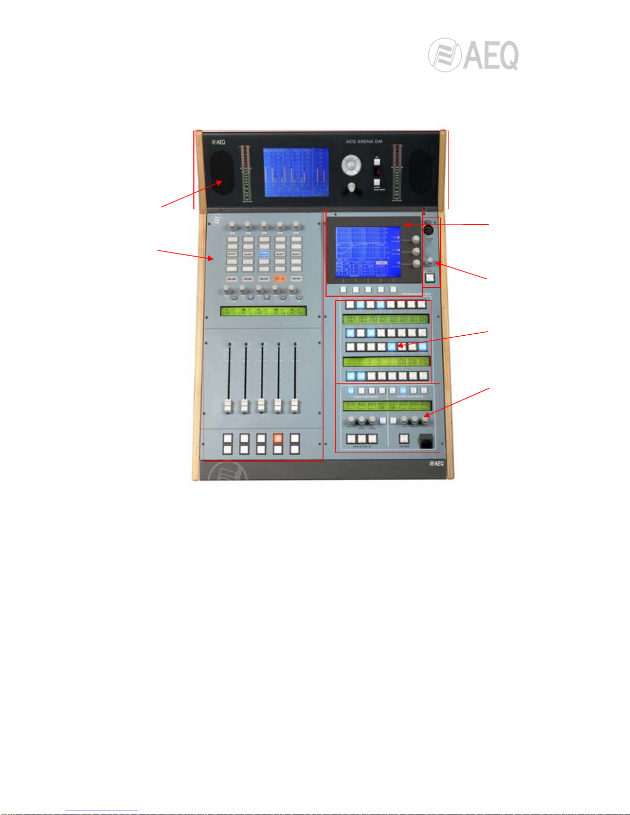
ARENA DM CONTROL SURFACE
FUNCTIONAL DESCRIPTION
2
CONTENTS
1. INTRODUCTION……………………………………………………………………................. 4
2. CONTROL SURFACE COMPONENTS DESCRIPTION……………................................ 5
2.1. Configuration and monitoring panel…………………………………………………... 6
2.2. Channels area…………………………………………………………………………... 8
2.2.1. Channel configuration in “Multiplex Mode”………..………………………... 9
2.2.2. Channel configuration in “Channel Setup Mode”………..…………………. 10
2.3. Configuration and information area…………………………………………………… 11
2.4. Talkback area…………………………………………………………………………… 11
2.5. Programmable keys area………………………………………………………………. 12
2.6. Monitoring area…………………………………………………………………………. 13
3. CONTROL SURFACE OPERATION…………………………………………………………. 15
3.1. Controls operation in the channels area……………………………………………… 15
3.1.1. Input gain adjustment for each channel…………………………………….. 15
3.1.2. Input Select & Set Up: Input sources selection and configuration for……
each channel…………………………………………………………………… 15
3.1.2.1. Input select…………………………………………………………… 16
3.1.2.2. Phase L-R…………………………………………………………..... 16
3.1.2.3. Mode………………………………………………………………….. 16
3.1.3. Dynamic Setup: Selection and configuration of dynamic and time……….
processing functions by channel, except equalization…………………….. 17
3.1.3.1. Compressor…………………………………………………………... 17
3.1.3.1.1. Compressor parameters adjustment…………………... 18
3.1.3.1.2. Saving and loading compressor settings...……………. 19
3.1.3.2. Noise Gate……………………………………………………………. 19
3.1.3.3. Reverb………………………………………………………………… 20
3.1.4. Equalizer: Selection and configuration of equalizer and filter functions,
by channel……………………………………………………………………..... 21
3.1.5. Routing: Sending selection and configuration for each channel……........ 23
3.1.6. Select: Access to the special functions display and controls…………….. 24
3.1.7. Cue: Cue function….………………………………………………………….. 24
3.1.8. On Air: Signal indicator……………………………………………………….. 24
3.1.9. Select / On. Routing encoder and associated pushbutton………………... 24
3.1.10. Opening and regulation of channels, channel label and page changes.. 25
3.2. Configuration and information area operation (Select)……………………………... 26
3.2.1. Functional description………………………………………………………… 26
3.2.1.1. Controls identification……………………………………………….. 26
3.2.1.2. Display states and associated information……………………….. 26
3.2.1.3. Processing……………………………………………………………. 27
3.2.1.3.1. Equalizer………………………………………………….. 30
3.2.1.3.2. Filter……………………………………………………….. 30
3.2.1.3.3. Reverb…………………………………………………….. 31
3.2.1.4. Test signal generation………………………………………………. 32
3.2.1.4.1. Tone generation………………………………………….. 32
3.2.1.4.2. Pink noise generation……………………………………. 33
3.2.1.4.3. White noise generation………………………………….. 33
3.2.1.5. Input/Output Setup…………………………………………………... 34
3.2.2. Select access area. General data display………………………………….. 35
3.2.3. Working Configuration display……………………………………………….. 36
3.2.3.1. Loading a new configuration……………………………………….. 36
3.2.3.2. Memory Configuration………………………………………………. 37
3.2.4. “Change User” display. Change current user………………………………. 39
3.2.5. “Macro Configuration” display. Load and activation of programmable…..
keys…………………………………………………………………………….. 40